CPW-Fed Reconfigurable Clover-Shaped Antenna with Switchable
Circular Polarization
Lingsheng Yang1, *, Yongan Zhu1, and Kuniaki Yoshitomi2
Abstract—In this paper, a CPW-fed reconfigurable clover-shaped antenna with switchable circular polarization is proposed. This antenna consists of a clover-shaped patch, four p-i-n diodes, and two pairs of quarter-circular-rings. By electrically controlling the four p-i-n diodes to form two orthogonal bow-tie shaped current paths, the proposed antenna can be operated in two modes: the left-hand circular polarization (LHCP) and right-hand circular polarization (RHCP) modes. Two pairs of quarter rings are used to improve the bandwidth and AR performance of the antenna. The measured 10-dB reflection coefficient and 3-dB axial-ratio (AR) bandwidth of the prototype antenna is approximately 12.3% and 19%, respectively, which is enough for some wireless applications such as WLAN IEEE 802.11 b/g (4%). Gain and radiation pattern are also presented.
1. INTRODUCTION
Recently, great attention has been paid to polarization reconfigurable antennas, since they can mitigate the multipath effects [1], and expand the capabilities of the communication systems [2]. Many researches of polarization switchable antennas have been reported [3–15]. In general, the antennas with switchable polarization are designed to form at least two polarization states, like LHCP and RHCP, while the method to obtain polarization reconfigurability is mainly with the aid of switching devices such as RF MEMS or p-i-n diodes. The RF MEMS has the advantages of low impedance, low parasitic capacitance and low insertion loss [3]. However, the p-i-n diode is more widely used because of its cheaper cost, faster response time and low power handling [4].
In [5], two p-i-n diodes were placed in the slots’ regions to attain reconfigurable polarization capability by controlling their states “ON” or “OFF”. E-shaped patch antennas were proposed in [6, 7], they achieved circular polarization diversity by using p-i-n diodes and RF MEMS, respectively. In [8], V-shaped coupling strip fed annular slot antennas with switchable polarization is reported, only two p-i-n diodes are involved in the reconfigurable design. The square-ring microstrip antennas was design for switchable circular polarization in [9, 10]. By adjusting the states of two diodes, the operating mode of the antenna can be electrically switched. Using some special feed structures can also achieve circular polarization [11, 12]. By electrically controlling the p-i-n diodes connected to the Y-shaped and T-shaped feeding line respectively, polarization reconfigurable antennas were obtained. CPW-fed planar antennas were widely used in reconfigurable antenna designs due to their simple structure [13–15]. In [13], a polarization reconfigurable CPW-fed slot antenna was proposed. The vertical and horizontal linear polarizations were obtained by changing the bias state of the two p-i-n diodes. Circular polarization diversity were realized in [14, 15]. In [14], by changing the bias states of the two PIN-diode embedded in the inverted-L-shape ground strips at the upper corner of square slots, RHCP and LHCP characteristics
Received 21 October 2015, Accepted 3 December 2015, Scheduled 18 December 2015
* Corresponding author: Lingsheng Yang ([email protected]).
1 Jiangsu Key Laboratory of Meteorological Observation and Information Processing & Research Center of Applied Electromagnetics
can be fulfilled. By inserting meander-line strip in the radiating stub and two L-shaped slots in the ground plane, a multi-band frequency performance and dual circular polarization characteristic can be realized [15]. The multi-band function was controlled by using four PIN diodes in the meander-line, while the circular polarization performance was determined by the bias states of the PIN diodes which were connected with the slots.
In this paper, we present a CPW-fed reconfigurable clover-shaped antenna with switchable polarization. The antenna is easy to fabricate. By changing the polarity of the bias voltage which is connected to four leaves, the bias state of the four p-i-n diodes can be controlled and the antenna acts as two orthogonal bow-tie patches. Therefore, the antenna can exhibit RHCP and LHCP performances. The antenna has a wide impedance matching and AR bandwidth, and measured gain and other results are also presented to show the competitiveness of the proposed antenna for WLAN and other wireless applications.
2. ANTENNA DESIGN
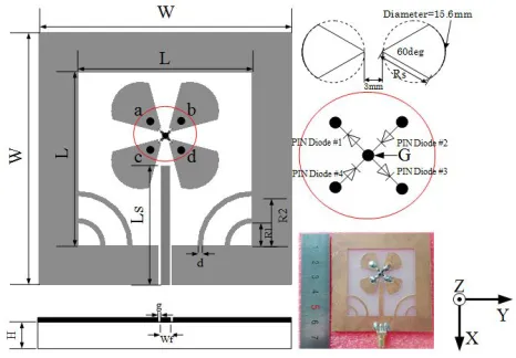
Figure 1 shows the geometry of the antenna proposed in this paper. The clover-shaped radiation part of the antenna is fabricated on an FR4 dielectric substrate with a permittivity of 4.4, loss tangent 0.02 and a thickness of 0.8 mm. The antenna is fed by a CPW structure, and the ground surrounds the radiation part with two pairs of quarter rings at the two bottom corners. Four p-i-n diodes (#1, #2, #3 and #4, part number BAV64-02V) are set at the center of the four leaves. In the forward bias state, the equivalent circuit of the p-i-n diode is represented by a resistor of 2.1 ohm. On the other hand, in the reverse bias state, the equivalent circuit of the p-i-n diode is presented by a capacitor of 0.17 pF. The mechanism of applying bias to the four p-i-n diodes is explained as follows.
The diodes junction “G” is connected to the ground plane through a via-hole, and the voltage of “G” is set as 0 V. The bias voltage V c is superimposed on the four leaves simultaneously by the four via-holes “a”, “b”, “c”, “d”. When the leaves are with positive voltage (slightly higher than 0 V for example 0.2 V), diodes #1 and #3 are in the ON state, while the other two diodes are in the OFF state. By the same principle, when the leaves are with negative voltage, diodes #2 and #4 are ON-state, the other two diodes are OFF-state. The proposed antenna can exhibit RHCP and LHCP on the basis of
Figure 1. Geometry and photograph of the proposed antenna.
Table 1. The parameters of the antenna.
Parameter W L H g Wf Value (mm) 65 45 0.8 0.3 3
Parameter Rs Ls R1 R2 d
the bias states of the four p-i-n diodes.
The leaf of the clover is formed in the shape of a fan from a circle. The diameter of the circle is 15.6 mm, and the corner angle of the fan is 60 degrees. The gap between the two symmetry leaves (like #a and #d) is 3 mm, enough for two diodes. The parameters of the antenna are listed in Table 1.
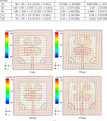
The comparison between the proposed antenna and recently published polarization reconfigurable antennas from size and performance view is listed in Table 2. By comparison, the proposed antenna has a compact size and acceptable bandwidth performances.
Table 2. Comparison between the proposed antenna and the recently published reconfigurable antennas.
Reference
antenna Size (mm
3) impedance bandwidth AR bandwidth
Proposed
antenna 65×65×0.8 (0.49λ×0.49λ) 2.28–2.58 GHz 2.04–2.60 GHz [2] 80×80×0.8 (0.63λ×0.63λ) 24 GHz±30 MHz 2438 GHz±10 MHz [6] 140×80×0.787 (1.12λ×0.64λ) 2.4∼2.575 GHz 2.38∼2.6 GHz [8] 100×100×1.6 (0.76λ×0.76λ) 2.29∼2.60 GHz 2.408 ∼2.518 GHz [11] 70×70×1.6 (0.56λ×0.56λ) 2.42∼2.56 GHz 2.48∼2.52 GHz [12] 70×70×1.6 (0.57λ×0.57λ) 2.43∼2.72 GHz 2.615–2.67 GHz
0 deg 90 deg
180 deg 270 deg
(b)
0 deg 90 deg
180 deg 270 deg
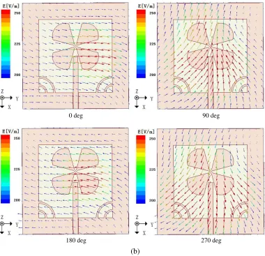
Figure 2. Simulated electric field vector on the proposed antenna at 2.45 GHz: (a) p-i-n diode #1 & #3 OFF- and #2 & 4 ON-state, (b) p-i-n diode #1 & #3 ON- and #2 & 4 OFF-state.
3. RESULTS AND DISCUSSION
Figures 2(a) and (b) show the simulated electric field vectors at a distance of 20 mm in the +z-axis direction of the antenna at 2.45 GHz for different phases. In Fig. 2(a), the p-i-n diodes #1 & #3 are OFF and #2 & #4 are ON. The two leaves which are connected with #2 & #4 are hold together like a bow-tie patch while the other two leaves are separated, the electric field vector rotates in the clockwise direction, and the antenna exhibits a LHCP property. Similarly, in Fig. 2(b), the p-i-n diodes #1 & #3 are ON and #2 & #4 are OFF, the antenna acts like a orthogonally crossed bow-tie patch and the electric field vector rotates in the anticlockwise direction which exhibits a RHCP property.
Figures 3(a) and (b) show the variation in reflection coefficient and the axial ratio of the proposed antenna with the change of the radiusRsof the leaves. As we can observe, the radiusRsaffects both the resonance frequency and axial ratio. With the increase ofRs, the resonant frequency shifts to the lower frequency. The optimization for design was carried out through the simulations using the HFSS ver.15, the antenna can obtain desired performance at 2.45 GHz. The final clover radius isRs= 13.5 mm.
(a) (b)
Figure 3. (a) Simulated reflection coefficient and (b) axial ratio of the proposed antenna for different value of Rs.
(a) (b)
Figure 4. (a) Simulated reflection coefficient and (b) axial ratio of the proposed antenna for different value of Ls.
(a) (b)
Figure 5. (a) Simulated reflection coefficient and (b) axial ratio of the proposed antenna with or without the quarter-circular-rings.
(a) (b)
Figure 6. (a) Simulated reflection coefficient and (b) axial ratio of the proposed antenna for different value of R1.
(a) (b)
Figure 7. (a) Simulated reflection coefficient and (b) axial ratio of the proposed antenna for different value of R2.
Figures 6 and 7 show the reflection coefficient and the axial-ratio of the proposed antenna with the change of the radius of inner-quarter-rings R1 and outer-quarter-rings R2, respectively. R1 slightly
affects the reflection coefficient and axial ratio of the antenna, and R2 affects both the reflection
coefficient and axial-ratio of the antenna more significantly. So in the antenna design, the inner-quarter-rings are for the fine-tuning and the outer-quarter-inner-quarter-rings are for the coarse-tuning. With inner and outer rings together, the process of adjusting antenna matching becomes easier.
Figure 8 shows the measured and simulated reflection coefficients in two circular polarization modes. According to the result, for both modes, the antenna can obtain measured 10-dB impedance bandwidth 300 MHz (2.28–2.58 GHz, 12.3%) at the center frequency about 2.43 GHz. The differences between simulation and measurement are probably caused by fabrication imperfection and quality variances in the material.
The measured axial ratio is shown in the Fig. 9. When the proposed antenna operates in the LHCP mode, the 3-dB axial ratio bandwidth is about 24% (2.04–2.60 GHz), and the measured minimum axial ratio is 1.09 dB at 2.25 GHz. While for the RHCP mode, the 3-dB axial ratio bandwidth is about 19% (2.10–2.55 GHz), and the measured minimum axial ratio is 1.01 dB at 2.34 GHz.
Figures 10(a) and (b) show the measured radiation pattern when the antenna works in LHCP state and RHCP state at 2.45 GHz, respectively. The cross polarization level is high than 10 dB in the whole operating band.
Figure 8. Simulated and measured reflection coefficient of the proposed antenna.
Figure 9. Measured axial ratio (AR) of the proposed antenna.
(a) (b)
(c)
Figure 10. Measured radiation patterns of the proposed antenna at 2.45 GHz: (a) p-i-n diodes #1 & #3 ON and #2 & #4 OFF, (b) p-i-n diodes #2 & #4 ON and #1 & #3 OFF, (c) cross polarization level.
4. PRACTICAL APPLICATION
(a) (b)
Figure 11. (a) Simulated and measured gain of the proposed antenna, (b) antenna efficiency.
(a) (b)
Figure 12. (a) Geometry and photograph of the proposed antenna with the reflector and (b) planar configuration of metal reflector.
(a) (b)
Figure 13. Simulated radiation patterns of the proposed antenna with the reflector at 2.45 GHz: (a) LHCP mode and (b) RHCP mode.
Table 3. The parameters of the reflector.
Figure 14. Simulated gain of the proposed antenna.
(a) (b)
Figure 15. (a) Simulated reflection coefficient and (b) axial ratio of the proposed antenna with the reflector.
5. CONCLUSION
This paper proposes a CPW-fed clover-shaped antenna with reconfigurable circular polarization capabilities. The LHCP and RHCP modes are changed by adjusting the bias states of the four p-i-n diodes. By using two pairs of quarter rings, the measured 10-dB impedance bandwidth is 12.3%, and the 3-dB AR bandwidth is wider than 19%. Radiation pattern and antenna gain are also presented. The proposed antenna is competitive for WLAN and other applications.
ACKNOWLEDGMENT
This work was supported by the Priority Academic Program Development of Jiangsu Higher Education Institutions (PAPD) and Jiangsu Innovation & Entrepreneurship Group Talents Plan.
REFERENCES
1. Yang, F. and Y. R. Samii, “A reconfigurable patch antenna using switchable slots for circular polarization diversity,” IEEE Microwave and Wireless Comp. Lett., Vol. 12, No. 3, 96–98, Mar. 2002.
3. Ho, K. M. J. and G. M. Rebeiz, “Microstrip antennas with full polarization diversity using packaged RF MEMS switches,” Chicago, USA, Jul. 8–14, 2012.
4. Aghdam, S. A., “Reconfigurable antenna with a diversity filtering band feature utilizing active devices for communication systems,” IEEE Trans. Antennas Propag., Vol. 61, No. 10, 5223–5228, Oct. 2013.
5. Yang, Z. X., H. C. Yang, J.-S. Hong, and Y. Li, “Bandwidth enhancement of a polarization-reconfigurable patch antenna with stair-slots on the ground,” IEEE Antennas Wireless Propag. Lett., Vol. 13, 579–582, Apr. 2014.
6. Khidre, A., K. L. Lee, F. Yang, and A. Z. Elsherbeni, “Circular polarization reconfigurable wideband E-shaped patch antenna for wireless applications,” IEEE Trans. Antennas Propag., Vol. 61, No. 2, 960–964, Feb. 2013.
7. Rajagopalan, H., J. M. Kovitz, and Y. R. Samii, “MEMS reconfigurable optimized E-shaped patch antenna design for cognitive radio,” IEEE Trans. Antennas Propag., Vol. 62, No. 3, 1056–1064, Feb. 2014.
8. Row, J. S., W. L. Liu, and T. R. Chen, “Circular polarization and polarization reconfigurable designs for annular slot antennas,” IEEE Trans. Antennas Propag., Vol. 60, No. 12, 5998–6002, Dec. 2012.
9. Tsai, J. F. and J. S. Row, “Reconfigurable square-ring microstrip antenna,”IEEE Trans. Antennas Propag., Vol. 61, No. 5, 2857–2860, May 2012.
10. Seo, D. and Y. Sung, “Reconfigurable square ring antenna for switchable circular polarization,”
Electronics Letters, Vol. 51, No. 6, 428–440, Mar. 2015.
11. Lee, S. W. and Y. J. Sung, “Reconfigurable Rhombus-shaped patch antenna with Y-shaped feed for polarization diversity,” IEEE Antennas Wireless Propag. Lett., Vol. 14, No. 3, 163–166, Feb. 2015. 12. Lee, S. W. and Y. J. Sung, “Simple polarization reconfigurable antenna with T-shaped feed,”IEEE
Antennas Wireless Propag. Lett., Vol. PP, No. 99, 1–4, Mar. 2015.
13. Li, Y., Z. Zhang, W. Chen, and Z. Feng, “Polarization reconfigurable slot antenna with a novel compact CPW-to-slot line transition for WLAN application,” IEEE Antennas Wireless Propag. Lett., Vol. 9, 252–255, 2010.
14. Zarei, V., M. Azarmanesh, H. Boudaghi, and S.-A. Aghdam, “A novel CPW-fed polarization reconfigurable microstrip antenna,” IEEE Microwave Measurement Conference (ARFTG), 1–4, Tampa, USA, Jun. 6, 2014.
15. Valizade, A., M. Ojaroudi, and N. Ojaroudi, “CPW-fed small slot antenna with reconfigurable circular polarization and impdeance bandwidth characteristcis for DCS/WiMAX applications,”
Progress In Electromagnetics Research C, Vol. 56, 65–72, 2015.