Reducing Harmonics Using Hysteresis Current Controller for
Pv System Integrated With Grid
Dr kamaraju sir, S.Venkatesh
M.tech,Kallepalli sravankumar
M.tech,P.Jithender
M.techAbstract
Photovoltaic (PV) systems proposes attractive alternative source of generation because these can be placed near to the load centers when compared with other renewable source of generation. Most of renewable energy systems works in conjunction with the existing electrical grids. Also, inverter technology has an important role to have a safe and reliable grid interconnection operation of renewable energy systems. It is also necessary to generate a high quality power to the grid with reasonable cost. They also must be capable of provide high efficiency conversion with high power factor and low harmonic distortion. For this reason, the control policy must be considered. Therefore, the most important current control techniques are investigated in this paper. This paper proposes the Comparison of Constant Current and Hysteresis Controlling Techniques for on grid PV system.
Keywords: PV system design, modeling, DC-DC Boost Converter, PWM inverter, PLL constant current control, Hysteresis Controlling Techniques.
I INTRODUCTION
W
orld is moving towards the greener sources of energy to make the planet pollution free and environment friendly. The major utilization of these sources with grid integration is the challenging task. It is therefore Distribution Generation particularly single phase rooftop Photo Voltaic system are major researcharea for grid integration, since these sources have huge opportunity of generation near load terminal. The rooftop application involving single phase Distribution Generation’s fed with Photo Voltaic source can be not only utilized for household use but the excess energy can be transferred to the grid through proper control scheme and adequate hardware.
Photo Voltaic systems can generate high voltages. Safety is therefore very important in order to avoid accidents and damage of expensive components and equipment. For safety reasons, solar arrays are normally earthed, either by placing a matrix of metal in the ground under the array, or by using conventional earth rods. It is normally not necessary to protect solar array from direct lightning strikes, provided that their mounting structure is well earthed. However, inverters or other electronics controls connected to the array should be protected. Blocking diodes are installed in solar arrays to prevent reverse current flows into the modules, which may damage the modules and cause energy losses. By-pass diodes are incorporated into modules to prevent damage of arrays when some cells or modules become shaded.
Photo Voltaic system requires regular maintenance to ensure proper operation and the full life of components. Some of the most
important maintenance tasks are cleaning of
modules front, Removal obstacles, tree
The rest of components of PV systems
require little or no maintenance. The
decentralized renewable energy production needs the continuous increase in the electrical energy with the clean environment. The increasing energy consumption may overload the distribution grid as well as power station and may cause the negative impact on power availability, security and quality.
The only solution to overcome this problem is integrating the utility grid with the renewable energy systems like solar energy, wind energy or hydro energy. As per the availability of renewable energy sources the grid can be connected to the renewable energy system. Because of abundant availability of solar energy recently the solar power generation systems are getting more attention, more efficient and more environment friendly as compared to the conventional power generation systems such as fossil fuel, coal or nuclear energy.
II CIRCUIT CONFIGURATION
The Photo Voltaic systems are still very expensive because of higher manufacturing cost of the Photo Voltaic panels, but the energy that drives them the light from the sun is free, available almost everywhere and will be still present for millions of years, even all non-renewable energy sources might be depleted. It has no moving parts this is one of the major advantage of Photo Voltaic technology. Therefore, the Photo Voltaic system is very robust, it has a long lifetime and low maintenance requirements. And, most importantly, it is environmentally friendly power generation. The disadvantage of the PV system is that it can supply the load only in sunny days. Therefore, for improving the performance and supplying the power in all day, it is necessary to
hybrid the Photo Voltaic system into another power generation systems or to integrate with the utility grid.
The integration of the Photo Voltaic system with the utility grid requires the PWM voltage source converter for interfacing the utility grid and results to some of the interface issues. A prototype current controlled power conditioning system has been developed and tested. This prototype sources 20 kW of power from a photovoltaic array with a maximum power point tracking control.
The disadvantage of this system is the need of high bandwidth current measurement transducers (dc to several times the switching frequency), and the need for relatively high precision in the reference signal generation. Hence, this increases the cost of the system. The inverters suitable for the PV system are central inverters, string inverters, module integrated or module oriented inverters, multi string PV inverter with new trends has been described below. If these solar inverters are connected with the grid, the control of these inverters can be provided using the phase locked loop. The need and benefits of the distribution technology has been presented in this paper. Single-phase Grid connected Photo Voltaic inverters with the control has been described with its advantages and disadvantages. The three-phase Photovoltaic power conditioning system with line connection has been proposed with the disturbance of the line voltage which is detected using a fast sensing technique.
This paper proposes the modeling of the grid connected Photo Voltaic system with the Constant Current Controller, which controls the solar inverter for interfacing the grid. The voltage level of DC voltage generated by the Photo Voltaic array is increased using the boost converter and then applied to the 3-ф, 2 level Solar inverter. The control of the solar inverter is provided through the Constant Current Controller. This controller uses the Phase Locked Loop and PI controllers. The Phase Locked Loop is used for tracking the phase angle of the grid voltage. The PI controller gains are chosen such that the Constant Current Controller generates the pulses for solar inverter according to the grid voltage. The proposed model is able to supply the 2 MW resistive loads and 30 MW, 2 MVAr load the applicable criteria that follows.
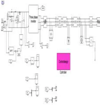
Fig 1 Circuit representation with constant current controller
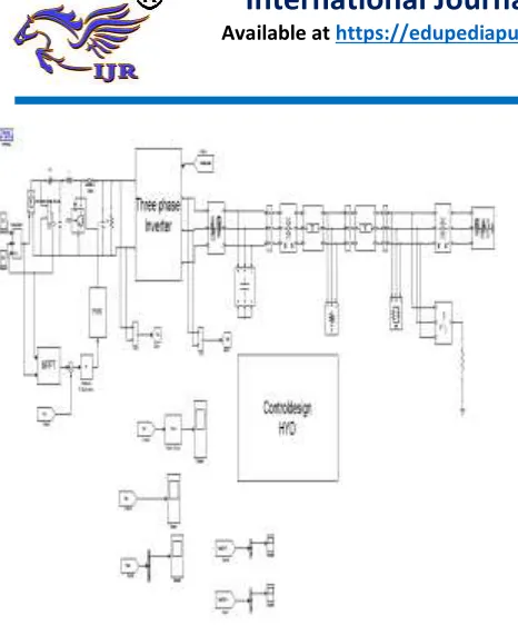
Fig 2 Circuit representation with hysteresis control.
III MAXIMUM POWER POINT TRACKING
3.1 P&O METHOD:
In
this
approach
voltage
is
periodically given a perturbation & the
corresponding output power is compared
with that at previous perturbing cycle if the
power increases due to that perturbation then
the perturbation is continued in the same
direction after peak power is reached at the
next instant perturbation is reverses power
will oscillates at peak power point in order
to maintain power variation very small the
perturbation size should be very small
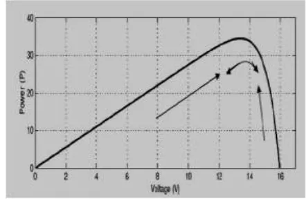
P&O method is the most frequently used algorithm to track the maximum power due to its simple structure and fewer required parameters. This method finds the maximum power point of PV modules by means of iteratively perturbing, observing and comparing the power generated by the PV modules. It is widely applied to the maximum power point tracker of the photovoltaic system for its features of simplicity and convenience. According to the structure of MPPT it is the relationship between the terminal voltage and output power generated by a PV module. It can be observed that regardless of the magnitude of sun irradiance and terminal voltage of PV modules, the maximum power point is obtained while the condition dP/dV= 0 is accomplished. The slope(dP/dV) of the power can be calculated by the consecutive output voltages and output currents, and can be expressed as follows,
3.2P&O Algorithm:
3.3 EQUATIONS:
V and I PV pannel voltage and currents
Vn and In are voltage and currents at nth intervals
Vb and Ib are voltage and currents at (n-1)th intervals
Pn=V(n)*I(n)
Pb=V(n-1)*I(n-1)
Δp=Pn-Pb
dP/dV= 0 maximum power condition
if dP/dV>0 then D- ΔD
if dP/dV<0 then D+ ΔD
ΔD=Perturbation D=duty cycle from switch
3.4 MPPT SIMULINK MODEL
The below figure represents the maximum power point algorithm SIMULINK model using the MATLAB software
Fig 3 maximum power point algorithm SIMULINK model
IV SIMULATION RESULTS
The simulation result are shows the concept of Comparison of Constant Current and Hysteresis Controlling techniques for PV system Integrated with Grid. The flowing figure represents simulink model for PV system integrated with grid using constant current controller. The following figure 5 represents simulink model for PV system integrated with grid using hysteresis controller. The following figure 6 represents simulink model of hysteresis controller to reduce the harmonics. The
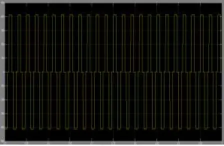
following figure 7 represents simulink design for hysteresis controller design. The following figure 8 represents simulation of proposed scheme at boost converter output. The following figure 9 represents simulation of proposed scheme at with filter. The following figure 10 represents simulation of proposed scheme at 2MW load. The following figure 11 represents simulation of proposed scheme at 30MW load. The following figure 12 represents simulation of proposed scheme at without filter. The following figure 13 represents simulation results using hysteresis controller.
Fig 5 Simulink model for PV system integrated with grid using hysteresis controller
Fig 6 Simulink model of hysteresis controller to reduce the harmonics
Fig 7 Simulink design for hysteresis controller design
Fig 8 DC voltage delivered by the boost
Fig 9 Inverter output voltage before filtering
Fig 10 Load current for supplying 2MW load
Fig 11 Load current for supplying 30MW load, 2 MVAr
Fig 12 Inverter output voltage after filtering
using constant current controller
Fig 13 Inverter output voltage after filtering using hysteresis controller
V CONCLUSION
This paper proposes the comparison of constant current and hysteresis controlling techniques for PV system integrated with Grid . Here while comparing two controllers ie constant current controller and hysteresis controller, to integrate the PV system with grid. All results will be same for both hysteresis controller and constant current controller, the only difference is in without filter results. When compared with constant current controller, by using hysteresis controller high efficiency conversion with high power factor and low harmonic distortion can be obtained. Hence From the above both constant current and hysteresis controlling techniques can be used to interface the PV system with grid but by
using advanced hysteresis controller