Improving Power Quality Of Distribution Grid Using An
Ultracapacitor Integrated With Power Conditioner
P Naresh1,V Sai Ganesh2, B Vinay Varshini3,K Nishitha4,Ekram Quershi4 5 1Asst. Professor, Department of EEE, Raghu Engineering College, Vishakapatnam India1
B.Tech Student, Department of EEE,Raghu Engineering2,3,4,5College, Vishakapatnam India.2
A B S T R A C T
Entrance of different sorts of disseminated vitality assets (DERs) like sun oriented, wind, and module half and half electric vehicles (PHEVs) onto the dispersion lattice is on the ascent. There is a comparing increment in power quality issues and discontinuities on the circulation lattice. With a specific end goal to diminish the discontinuities and enhance the power nature of the conveyance framework, a ultracapacitor (UCAP) incorporated power conditioner is proposed in this paper. UCAP incorporation gives the power conditioner dynamic power capacity, which is valuable in handling the lattice irregularities and in enhancing the voltage hang and swell pay. UCAPs have low vitality thickness, high-control thickness, and quick charge/release rates, which are all perfect qualities for meeting high-control low-vitality occasions like sags/swells. In this paper, UCAP is coordinated into dc-connection of the power conditioner through a bidirectional dc–dc converter that aides in giving a hardened dc-interface voltage. The reconciliation helps in giving dynamic/responsive power bolster, irregularity smoothing, and list/swell pay. The aggregate consonant bending was lessened by utilizing fuzzy controller. Plan and control of both the dc–ac inverters and the dc–dc converter are talked about. The reproduction performed in MATLAB/SIMULINK condition.
Index terms—Active power channel (APF), dc–dc converter, d–q control, dynamic voltage restorer(DVR), vitality stockpiling combination, droop/swell, ultra capacitors(UCAP),fuzzy controller.
I. INTRODUCTION
Control quality is significant reason for worry in the business, and it is imperative to keep up great power qualityon the lattice. Thusly, there is reestablished enthusiasm for power quality items like the dynamic voltage restorer (DVR) and dynamic power channel (APF). DVR keeps delicate burdens from encountering voltage droops/swells and APF keeps the matrix from providing nonsinusoidal streams when the heap is
for lessening the discontinuities in wind power is proposed. It is clear from the writing that inexhaustible discontinuity smoothing is one application that requires dynamic power bolster from vitality stockpiling in the seconds to minutes time scale . Receptive power support is another application which is increasing wide acknowledgment with recommendations for responsive power evaluating. Voltage hang and swells are power quality issues on appropriation matrix that must be moderated. list/swell pay needs dynamic power bolster from the vitality stockpiling in the milliseconds to 1 min length . All the above functionalities can be acknowledged by incorporating vitality stockpiling into the network through a power conditioner topology. Of all the rechargeable vitality stockpiling advances superconducting magnet vitality stockpiling (SMES), flywheel vitality stockpiling framework (FESS), battery vitality stockpiling framework (BESS), and ultracapacitors (UCAPs), UCAPs are perfect for giving dynamic power support to occasions on the conveyance lattice which require dynamic power bolster in the
Fig. 1. One-line diagram of power conditioner with UCAP energy storage.
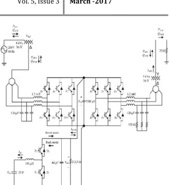
Fig. 2. Model of power conditioner with UCAP energy storage.
seconds to minutes time scale like voltage hangs/swells, dynamic/responsive power bolster, and sustainable discontinuity smoothing . In this paper, UCAP-based vitality stockpiling mix through a power conditioner into the circulation matrix is proposed, and the accompanying application ranges are tended to
1) Integration of the UCAP with power conditioner framework gives the framework dynamic power capacity.
2) Active power ability is vital for autonomously repaying voltage hangs/swells and to give dynamic/receptive power support and discontinuity smoothing to the network.
3) Simulation approval of the UCAP, dc–dc converter, inverter their interface, and control.
4) Development of inverter and dc–dc converter controls to give hang/swell remuneration and dynamic/receptive support to the dissemination network.
II. THREE-PHASE INVERTERS
A. Control Stage
source inverters associated through a dc-interface capacitor. UCAP vitality stockpiling is associated with the dc-interface capacitor through
a bidirectional dc–dc converter. The arrangement inverter is in charge of remunerating the voltage lists and swells; and the shunt inverter is in charge of dynamic/responsive power bolster and sustainable discontinuity smoothing. The entire circuit outline of the arrangement DVR, shunt APF, and the bidirectional dc–dc converter is appeared in Fig. 2. Both the inverter frameworks comprise of IGBT module, its door driver, LC channel, and a segregation transformer. The dc-connect voltage Vdc is directed at 260 V for ideal voltage and current pay of the converter and the line–
line voltage Vab is 208 V. The objective of this venture is to give the coordinated power conditioner and UCAP framework with dynamic power ability
1) to remunerate impermanent voltage droop (0.1–0.9 p.u.) and swell (1.1–1.2 p.u.), which last from 3 s to 1 min ; and 2) to give dynamic/receptive support and inexhaustible discontinuity smoothing, which is in the seconds to minutes time scale.
B. Controller Implementation
The arrangement inverter controller execution depends on the in-stage pay strategy that requires PLL for
assessing θ, and this has been executed utilizing the
invented control technique portrayed in [4]. In view of
the evaluated θ and the line–line source, voltages Vab, Vbc, Vca (which are accessible for this delta-sourced framework) are changed into the d–q space and the line–neutral segments of the source voltage Vsa, Vsb, and Vsc which are not accessible can then be assessed utilizing
=
cos cos − cos +
− sin − sin − − sin + ∗
These voltages are standardized to unit sine waves utilizing line–neutral framework voltage of 120 Vrms as reference and contrasted and unit sine waves in-stage with real framework voltages Vs from (2) to discover the infused voltage references Vref important to keep up a consistent voltage at the heap terminals, where m is the tweak list, which is 0.45 for this case. In this manner, at whatever point there is a voltage list or swell on the source side, a comparing voltage Vinj2 isinjected in-stage by the DVR and UCAP framework to nullify
end. The real dynamic and responsive power provided by the arrangement inverter can be processed utilizing (3) from the rms estimations of infused voltage Vinj2a and load current ILa and ϕ is the stage distinction between the two waveforms.
The shunt inverter controller execution depends on the id− iq strategy, which is adjusted to give dynamic and
receptive power pay, to such an extent that id controls the responsive power and iq controls the dynamic power. Along these lines, in light of the references for dynamic and receptive forces Pref and Qref , the reference streams iqref and idref in d–q area can be computed utilizing (4), where vsq is the framework voltage in q-space and the reference ebbs and flows are ascertained utilizing (5).
III.FUZZY LOGIC CONTROL
FLC dictated by the arrangement of phonetic guidelines. The scientific displaying is not required in fuzzy controller because of the change of numerical variable into etymological factors. FLC comprises of three section: a. Fuzzification, b. Obstruction motor, c. Defuzzification. The fuzzy controller is described as; For each info and yield there are seven fuzzy sets. For effortlessness a participation capacities is Triangular. Fuzzification is utilizing constant universe of talk. Suggestion is utilizing Mamdani's "min" administrator. Defuzzification is utilizing the "stature" strategy. FLC piece outline as appeared in figure 2.
a. Fuzzification
Enrollment work qualities are appointed to the phonetic factors, utilizing seven fuzzy subsets: NB(Negative Big), NM(Negative Medium), NS (Negative Small), ZE (Zero), PS (Positive Small),PM(Positive Medium) and PB (Positive Big). The parcel of fuzzy subsets and the state of enrollment capacity adjust the get down to business to proper framework. Input blunder E(k) and change in mistake CE(k) of qualities which is standardized by an info scaling element as appeared in table 1.
In this system the input scaling factor is between -1 and +1 has design. The triangular shape of the membership function of this arrangement presumes that for any particular input there is only one dominant fuzzy subset . The input error E(k) and change in error C(k) for the FLC is given as
A few piece techniques, for example, Max-Min and Max-Dot have been proposed and Min strategy is utilized. Least administrator and Maximum administrator of yield participation capacity is of each control and it is appeared in Table 1.
c. Defuzzification
As a plant more often than not requires a non-fuzzy estimation of control, a defuzzification stage is required. To process the yield of the FLC, "stature" technique is utilized and the FLC yield changes the control yield.
Facilitate, the yield of FLC controls the switch in the inverter. Keeping in mind the end goal to control these parameters, they are detected and contrasted and the reference values. To accomplish this, the participation elements of Fuzzy controller are: mistake, change in blunder and yield as appeared in Figs.(3), (4). In the present work, for fuzzification, nonuniform fuzzifier has been utilized. In the event that the correct estimations of blunder and change in mistake are little or extensive, they are partitioned on the other hand.
The α is self-customizable element and to direct operation. E is the mistake of the framework, C is the adjustment in blunder and u is the control variable. On the off chance that the framework is not in adjusted it shows a blunder "E" if the esteem is extensive. While the blunder "E" esteem is little it demonstrates that the framework is close to adjusted state. In the event that framework is lopsided, the control factors ought to be extend to adjust the framework as right on time as could reasonably be expected. For framework solidness overshoot assumes a vital part. For limiting motions and framework dependability it requires less overshoot. "C" assumes an essential part, while the part of "E" is reduced. The streamlining is finished by α. The arrangement of
Fuzzy controller tenets is given in Table 1.
IV.SIMULATION RESULTS
The larger amount incorporated controller is intended to settle on framework level choices on the inverter and dc–dc converter controllers. In light of different framework parameters like Pload, Qload, Pgrid, Qgrid, Vucap, Vdc, Idclnk, and Iucap, the larger amount incorporated controller will settle on working in one of the accompanying modes: dynamic power bolster mode, receptive
control bolster mode, inexhaustible irregularity smoothing mode, droop/swell remuneration mode, and UCAP Charge mode. In dynamic power bolster mode and inexhaustible discontinuity smoothing mode, the UCAP-PC framework must give dynamic energy to the lattice. Along these lines, the dynamic power ability of the UCAP-PC framework must be surveyed by the larger amount coordinated controller. In light of the Pgrid and Pload values, the reference Pref is computed in the larger amount coordinated controller, and it will choose if the UCAP has enough vitality to react to the Pref charge in view of the UCAP condition of charge. On the off chance that the UCAP has enough ability to react to the demand, then the dc–dc converter controller is worked in lattice bolster mode; else, it is worked in control mode, where the UCAP is energized and the power demand is met at a later time. In matrix bolster mode, the dc–dc converter will work in a bidirectional manner in both Buck and Boost modes to react to the dynamic power asks for and manage the dc-connect voltage in a steady mold, while the inverter controller ought to react with the end goal that the summoned Pref is provided by the inverter through current control. In receptive power bolster mode, the UCAP-PC framework must give responsive energy to the matrix. In this mode, the UCAP-PC does not give any dynamic energy to the matrix and even the PC misfortunes are provided by the network. In light of the Qgrid and Qload values, the reference Qref is figured in the larger amount incorporated controller. In this mode, the dc–dc converter controller can be modified to work in framework bolster mode straightforwardly in light of the fact that the dynamic power prerequisite for working in this mode is insignificant. Accordingly, the objective of the dc–dc converter controller is to direct the dc-connect voltage in astable design, while the inverter controller ought to react with the end goal that the ordered Qref is provided by the inverter through current control.
Ig-3 FFT ANALYSIS: (TOTAL HARMONIC DISTORTION)
Fig-4 FFT ANALYSIS USING FUZZY CONTROLLER:
Fig,5 simulation diagram
V.CONCLUSION
In this venture, the idea of coordinating UCAP-based rechargeable vitality stockpiling to a power conditioner framework to enhance the power nature of the dispersion matrix is displayed. With this coordination, the DVR segment of the power conditioner will have the capacity to autonomously remunerate voltage hangs and swells and the APF bit of the power conditioner will have the capacity to give dynamic/receptive power bolster and sustainable discontinuity smoothing to the
bidirectional dc–dc converter at the dc-connection of the power conditioner is proposed. The control technique of the arrangement inverter (DVR) depends on inphase remuneration and the control methodology of the shunt inverter (APF) depends on id− iq strategy. Plans of real
segments in the power phase of the bidirectional dc–dc converter are talked about. Normal current mode control is utilized to manage the yield voltage of the dc–dc converter because of its intrinsically stable trademark. A more elevated amount coordinated controller that takes choices in view of the framework parameters gives contributions to the inverters and dc–dc converter controllers to complete their control activities. The aggregate consonant bending was diminished when fuzzy controller supplanted by PI controller.The recreation of the incorporated UCAP-PC framework which comprises of the UCAP, bidirectional dc–dc converter, and the arrangement and shunt inverters is completed utilizing MATLAB/SIMULINK. The reenactment of the UCAP-PC coordinated framework is introduced and the capacity to give transitory voltage droop pay and dynamic/responsive power bolster and inexhaustible discontinuity smoothing to the dissemination network is tried. Comes about because of reenactment and examination concur well with each other in this way confirming the ideas presented in this paper. Comparable UCAPbased vitality stockpiles can be sent later on in a microgrid or a low-voltage dissemination lattice to react to element changes in the voltage profiles and power profiles on the circulation framework.
REFERENCES:
[1] Deepak Somayajula, Student Member, IEEE, and Mariesa L. Crow, Fellow, IEEE,” An Ultracapacitor Integrated Power Conditioner for Intermittency Smoothing and Improving Power Quality of Distribution Grid” , IEEE TRANSACTIONS ON SUSTAINABLE ENERGY, VOL. 5, NO. 4, OCTOBER 2014
[2] N. H. Woodley, L. Morgan, and A. Sundaram,
“Experience with an inverter-based dynamic voltage
restorer,” IEEE Trans. Power Del., vol. 14, no. 3, pp. 1181–1186, Jul. 1999.
[3] J. G. Nielsen, M. Newman, H. Nielsen, and F.
Blaabjerg, “Control and testing of a dynamic voltage restorer (DVR) at medium voltage level,” IEEE Trans. Power Electron., vol. 19, no. 3, pp. 806–813, May 2004.
[4] V. Soares, P. Verdelho, and G. D. Marques, “An
instantaneous active and reactive current component
method for active filters,”IEEE Trans. Power Electron., vol. 15, no. 4, pp. 660–669, Jul. 2000.
to Power Conditioning, 1st ed. Hoboken, NJ, USA: Wiley/IEEE Press, 2007.
[6] K. Sahay and B. Dwivedi, “Supercapacitors energy
storage system for power quality improvement: An
overview,”J. Energy Sources, vol. 10, no. 10, pp. 1–8, 2009.
[7] B. M. Han and B. Bae, “Unified power quality
conditioner with super-capacitor for energy storage,”
Eur. Trans. Elect. Power, vol. 18, pp. 327–343, Apr. 2007.
[8] P. F. Ribeiro, B. K. Johnson, M. L. Crow, A. Arsoy,
and Y. Liu, “Energy storage systems for advanced power applications,” Proc. IEEE, vol. 89, no. 12, pp. 1744–1756, Dec. 2001.
[9] A. B. Arsoy, Y. Liu, P. F. Ribeiro, and F. Wang,
“StatCom-SMES,”IEEE Ind. Appl. Mag., vol. 9, no. 2, pp. 21–28, Mar. 2003.
[10] J. Rittershausen and M. McDonagh, Moving Energy Storage from Concept to Reality: Southern California Edison’s Approach to Evaluating Energy
Storage [Online]. Available:
http://www.edison.com/content/ dam/ eix/documents/innovation/smart-grids/Energy-Storage-Concept-to- Reality-Edison.pdf, accessed on 15 Jul., 2014.
AUTHOURS:
P NARESH currently working as a Asst. Professor, in Department of EEE, Raghu Engineering College, Vishakapatnam India. His interested areas are power quality and control, non renewable energy sources.
Sai Ganesh pursuing B.TECH in Raghu Engg.college ,vishakapatnam. His interested areas are power systems and power electronics.
B V Varshini pursuing her B.TECH in Raghu Engg.college ,vishakapatnam. Her interested areas are power systems and electrical and electronic measurements.
K Nishitha pursuing her B.TECH in Raghu Engg.college ,vishakapatnam. Her interested areas are power electronics and control systems.
Ekram Quershi pursuing his B.TECH
in Raghu Engg.college