Available Online at www.ijpret.com 12
INTERNATIONAL JOURNAL OF PURE AND
APPLIED RESEARCH IN ENGINEERING AND
TECHNOLOGY
A PATH FOR HORIZING YOUR INNOVATIVE WORK
MODELLING, ANALYSIS AND OPTIMIZATION OF LIFTING MECHANISM OF
DAM GATE OPENING HOIST MACHINE
RESHMA KHARCHE1, PROF. G. P. PATIL2, PROF. N. A. KHARCHE3
1. P. G. Student, Mechanical Engineering Department, Padm. Dr. V. B. Kolte College of Engineering, Malkapur. Maharashtra, India. 2. Associate Prof. Mechanical Engineering Department, Padm. Dr. V. B. Kolte College of Engineering, Malkapur. Maharashtra, India. 3. Assistant Prof. Mechanical Engineering Department, Padm. Dr. V. B. Kolte College of Engineering, Malkapur. Maharashtra, India.
Accepted Date: 08/01/2016; Published Date: 01/02/2016
\
Abstract: - An optimum design of lifting mechanism, well-equipped and efficient control system and trustable mechanism to lift the gate is important from technical point of view. If fails or not open at required speed creates a major problem to the dam & ultimately for public site. Hoist is electrically driven and fully enclosed gear reduction units, protected and interconnected shafting with flexible couplings grooved drums, and steel or stainless steel cables. Worm or spur gears are provided and are self-locking to hold the gate in position without the use of motor break. The hoist of the dam gate consists of a speed reduction gear mechanism that increases the torque & helps us to lift the gate with less effort. It is very important to know the breaking load and to design and analyse the load at which hoist can work or fail. Therefore, by using CATIA and ANSYS, we can analyse the drum gear assembly which is a key part at different loads. This review is performed for optimization of drum gear assembly of lifting mechanism by considering two different materials.
Keywords: Modelling, Lifting, Hosit Machine
Corresponding Author: MS. RESHMA KHARCHE
Access Online On:
www.ijpret.com
How to Cite This Article:
Reshma Kharche, IJPRET, 2016; Volume 4 (6): 12-33
Available Online at www.ijpret.com 13 1.0 INTRODUCTION
A hydraulic gate is a control equipment used for, controlling the flow of water through any component of the irrigation system. Generally it holds the water on the upstream side though some gates deal with a reversible water flow in special cases.
Gates of the radial or trainer type are used as sluice gates, spillway gates, submerged intake gates and log chute gates. They consist of a curved skin plate reinforced with structural members, and radial arms transmitting the water pressure to two trunion bearings. Radial gates rotate about a horizontal axis, which passes through the centers of trunion bearings and usually coincides with the axis of the skin plate. With this arrangement, the line of action of the water pressure passes through the centers of trunion bearings and no unbalanced moments are created. Sometimes the center of skin plate curvature is placed above the trunion center line to provide a lifting moment assisting the hoist in operating the gate. This moment must be less than due to the weight of the structure by a good margin, to assure positive gate closing. The moment due to the weight of the gate may be partly balanced by a counter weight, which may be either attached to an extension of the gate. Arms on the side of the trunion opposite to the gate leaf, or may be attached to the gate structure by a wire rope or chain and made to run on sloping rails embedded in the downstream face of the pier. Radial gates have been made in sizes as large as 65ft. square and as long as 80 ft. Water pressure usually acts on the convex side of the gate and trunions are in compression. Sometimes the water pressure is applied to the concave side of the gate; trunion bearings are submerged and radial arms in tension.
2.0 LITERATURE REVIEW
C. K. Sehgal and F. G. Ala studied various types of hoists and gates and found out cost effective hoist and gates as per their performance and maintenance. Wire rope hoists are no doubt simpler to operate than the hydraulic hoists (no air in system to worry about, no checking of fluid level, no leakage, filtration or contamination problems) also, presented the operation advantages, disadvantages and maintenance of Hoisting Equipment for dams. [1]
Available Online at www.ijpret.com 14
This standard fully reflects new experience on design, manufacturing, installation and operation of large and medium gate hoist on basis of survey and research. Also, it specifies design principle, load, material and mechanism of gate hoist. The hoist and various types of hoists are studied in it and safety of gate hoist against wind and slide. [3]
M. Barker, B. Vivian, J. Matthews and P. Oliver discussed the reliability issues of radial gates at Glenmaggie Dam in Victoria and drum gates at Little Nerang Dam in Queensland. The Glenmaggie dam radial gates are manually controlled using electrically driven (mains and diesel generator power supply) hoist motors with a petrol driven hydraulic pack for use in the event of complete electrical power supply failure. The application of a detailed fault tree analysis for the radial gated Glenmaggie Dam spillway has been used in a risk assessment to assist in the evaluation of the requirements for remedial works and provide guidance for operation of the gated systems. The drum gate operating system of Little Nerang Dam has been evaluated in some detail to provide the required operation and maintenance procedures necessary to ensure the risk is kept within the acceptable tolerable limits. The historical failure rate for these gates has been used in a simplified risk analysis performed for the gates to determine the societal risk. As a result of the risk analyses performed over the last few years, measures were taken by the dam owner to reduce the population at risk by purchasing downstream property as a means of reducing the risk to life. [4]
Richard L. Stockstill, E. Allen Hammack, and John E. Hite, Jr. presented a review of design guidance and hydraulic parameters associated with lock culvert valves. This report provides information on three valve designs commonly used to control culvert flow: vertical lift valves, conventional tainter valves, and reverse tainter valves. This engineering manual states that if a vertical-lift valve is used, the design should be tested in a hydraulic model “to develop an optimum bottom shape for the gate and to determine valve hoist loads.” [5]
This report gives details about field Investigations and data collection which gives information for evaluating existing structures and equipment and developing conceptual design. During Mechanical investigation, one of the gate of three existing gates did not open completely because the guide in dam had deteriorated. So, Cable and hoist mechanism for raising gates are replaced instead of guides. Also, the reconstruction report discusses about cost estimate and construction schedule. [6]
Available Online at www.ijpret.com 15
the gate hoist. All designs have a theoretical reserve lift capacity, but only physical testing can validate and accurately set the reserve lift capacity. [7]
This safety standard applies to the design of lifting equipment. First of all, it provides all the basic definitions such as maximum operating load, lifting capacity, machine parts, then additional requirements for various lifting devices. Hoist section applies to drive mechanisms and rope drives. While using hoist, it shall be equipped with a meter for counting running hours or load collectives. Also, the meter provides continuous monitoring. [8]
Jelena Markovic-Brankovic, Helmut Drobier presents new smooth upstream face high head gate form that heavily reduces hydrodynamic forces in conjunction to a total absence of uplift. Experiments done and identified number of changes in design which would reduce down pull and nevertheless cost. After numerous attempts, an acceptable construction modification was found in model. [9]
This standard covers general requirements for steel wire ropes for use in hoist, cranes, excavators and other engineering purposes. [10]
This standard provides design criteria and design of mechanical parts, hoisting capacity, Hoist supporting, Structure, electrical equipment’s, Standard values such as breaking strength, factor of safety, formulae for diameter of drum, grooves on drum. etc. [11]
3. Design Aspect
3.1 Design Calculation Of Hoist:
3.1.1 Capacity of hoist
Capacity of Hoist = 20 tons
= 20,000 kg
= 22000 taking into consideration the seal friction and wheel friction
3.1.2 Selection of wire rope
It is assumed that load is not shared equally by two suspensions and is taken 40% and 60% for design purpose so we take heavier load and design both rope for same.
Available Online at www.ijpret.com 16
= 13,200kg.
Load on each wire rope = 6600 kg.
Assuming F.O.S = 6 for hoist
“Breaking load on rope= 6600 * 6
=39600kg.
Selecting wire having tensile strength of 160 * 170 kg/m2
of group 6 x 37,
39600 = 510 d2
d = 2.78 cm
= 27.8 mm
Selecting standard wire size of 32 mm diameter.
3.1.3 Design of drum
Drum diameter should be kept minimum possible because it will reduce torque on gear there by decreasing the size of gear
Usual practice is to take diameter of drum as 20 * diameter of rope
Pitch diameter of drum = 20 * 32 = 640 mm
The drum can be either made by C.I. or fabricated from steel plate. C.I. drum are preferred because of ease in machining.
Then we have to find grooved length
N1= 2*Lift of gate/π *Pitch diameter of Drum.
= 2 *16 / π * 0.64
= 15.92 ≈16 No.
Available Online at www.ijpret.com 17
= 16+ 3
Proposed No of grooves = 19
Pitch of groove = 27+ 3 2.5 if diameter less than 27
= 30 mm 3 if diameter more than 27
Groove length of drum = no of groove * pitch of groove
= 19*30
= 570 mm.
Length of drum = 2 (groove length + free space)
=2 (570 +200 +80 +12)
=1712 mm
Radius of groove = 0.53 * diameter of rope
= 32.53 mm
Depth of groove = 0.35 * diameter of rope
= 0.35*32 mm.
= 11.2 mm.
Thickness of drum under groove (t) = 0.09 * Pitch diameter of drum.
= 0.09 * 640
= 57.6 mm ≈ 60 mm.
Core diameter = Pitch diameter of drum – 2t
= 640 – 2*(60) =520 mm
3.1.4 Selection of Motor:
Lifting speed is assumed as 2.5m/min. (2.5m/min)
Available Online at www.ijpret.com 18
= Motor rpm / First gear ratio * second gear ratio * reduction ratio
= 960 / (93/19) * (90/19) * 1/60.
= 2495 ≈ 2500
Lifting time = Lift / N
= 16000 / 2500
= 6.4 mm.
It should be below 60min.
As per I.S.
Of various units
Warm reducer =60%
Drum gear and 2nd pinion
Drum = 90%
Over all efficiency = 0.6 * 0.97 * 0.9 * 0.9
= 0.447
H.P. of motor = Lifting speed *load on hoist / η * 4500
= 0.5* 22000 / 0.447 * 4500
= 508 HP
Selecting motor of 10 HP 960 rpm.
3.1.5 Stresses of gear & pinion:
A] Torque on drum= Load on rope * 2 * P.C.D. drum / 2
= 6600 * 2 * 640 / 2
= 4224 kg m.
Available Online at www.ijpret.com 19
Torque on drum gear = Torque on drum/η
= 4224/0.9
= 4694 kg m = 4694* 9.81 Nm
= 46048.14Nm
B] Torque on 1st pinion shift=Torque on drum / 1stG.T.ratio * η
= 4224 / (93/19)*0.9
= 958.99
= 960 kg m
= 8559 Nm.
C] Torque on second pinion shaft = Torque on 1st pinion shift /Second gear train ratio * η
= 960 / (90/16) * 0.9
= 190.1 Kgm.
D] Tangential tooth load on 1st gear=Torque on gear 1 / P.C.D. of 1st gear/2
= 4684 / 1116 / 2
= 8.412 kg m
E] T.T.L. on 1st pinion =Torque on 1st pinion /PCD of pinion/2
= 960 / (228/2)
= 8.42 Kgm.
4. FINITE ELEMENT FORMULATION
Available Online at www.ijpret.com 20 CAD/CAE software’s are used.
CATIA V5 R19 - For 3D Component Design and Assembly
ANSYS Workbench 11.0 - For FEM analysis
4.1 A General Procedure for Finite Element Analysis
Certain steps in formulating a finite element analysis of a physical problem are common to all such analyses, whether structural, heat transfer, fluid flow, or some other problem. These steps are embodied in commercial finite element software packages (some are mentioned in the following paragraphs) and are implicitly incorporated in this text, although we do not necessarily refer to the steps explicitly. The steps are described as follows.
Available Online at www.ijpret.com 21 4.2 Finite Element Analysis of Gear 1
Input for FEM analysis (As per design calculation done)
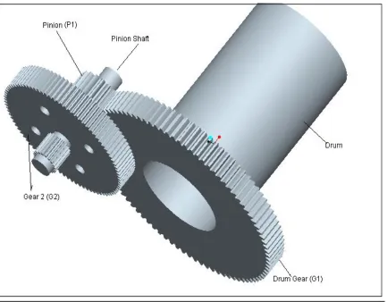
Fig 4.2 CATIA Model of Total Assembly
Torque Inputs
Torque on Drum Gear (G1) = 46048.14 Nm = 46050Nm
Torque on 1st Pinion Shaft = 8559Nm = 8560Nm
Torque on 2nd Pinion Shaft = 1864.88Nm = 1865Nm
Tangential Force Inputs
Force on Gear 1 = 8.412 Kg = 82.52N
Available Online at www.ijpret.com 22 4.3 Finite Element Analysis with two different Materials
In finite element analysis of two different materials have done static structural analysis by putting values of properties like young’s Modulus, Poisson’s ratio, density in ANSYS. In force analysis have calculated total deformations, equivalent stress, maximum shear stress, shear stress, Maximum principle stress. The detailed analysis of two different materials with their values of properties are described below comparatively.
Table 4.1 Material Properties of Alloy Steel and Cast Iron. [14]
Properties Alloy Steel Cast Iron
Young’s Modulus (E)Mpa 2.4x10⁶Mpa 1.2x 10⁶Mpa
Poisson’s Ratio (ν) 0.28 0.24
Density (ρ) Kg/m3 7854 6480
4.4 FEM Analysis of Gear 1 with Alloy Steel and Cast Iron.
Available Online at www.ijpret.com 23 Fig 4.4 Equivalent (von –Mises) Stress induced in Alloy Steel and Cast Iron.
Available Online at www.ijpret.com 24 Fig 4.6 Maximum Shear Stress induced in Alloy Steel and Cast Iron.
Available Online at www.ijpret.com 25 Fig 4.8 Shape Finder for Alloy Steel and Cast Iron
4.5 FEM Analysis of Pinion Gear 1 with Alloy Steel and Cast Iron.
Available Online at www.ijpret.com 26 Fig 4.10 Equivalent (von-Mises) Stress induced in Alloy steel and Cast Iron.
Available Online at www.ijpret.com 27 Fig Fig 4.12 Maximum shear stress induced in Alloy Steel and Cast Iron.
Available Online at www.ijpret.com 28 Fig 4.14 Shape Finder for Pinion gear of Alloy Steel and Cast iron.
4.6 FEM Analysis of Drum Gear Assembly with Alloy Steel and Cast Iron.
Available Online at www.ijpret.com 29 Fig 4. 16 Equivalent (von- Mises) Stress induced in Alloy Steel and Cast iron Assembly
Available Online at www.ijpret.com 30 Fig 4.18 Maximum Shear Stress induced in Alloy Steel and Cast Iron of Assembly
Fig 4.19 Maximum principal Stress induced in Alloy steel and Cast Iron Assembly
5.0 RESULTS AND DISCUSSION
Available Online at www.ijpret.com 31 Table 5.1 Comparison of Materials on the basis of Optimized mass
Parts of drum Gear Assembly Gear 1 Pinion Gear1
Optimized Mass
Alloy Steel Cast Iron Alloy Steel Cast Iron
638.64 526.46 31.532 26.011
Using two materials, Alloy steel and Cast iron the analysis performed in ANSYS and found that alloy steel is best suitable material for lifting mechanism having optimized weight
5.1 Final Result Sheet
These result tables are shown below. The Green color shows best result.
Table 5.2 Final Results for both materials
Full Assembly Gear 1( G1) Pinion Gear (p1)
Material used Alloy Steel Cast Iron Alloy Steel Cast Iron Alloy Steel Cast Iron Total Deformation(mm) 2.8825e-006 m 5.5831e-006 m 1.5876e-006 m 3.0867e-006 m 1.2192e-005 m 2.3762e-005 m
Equivalent Stress (Mpa)
18.967 18.979 15.636 15.639 319.49 319.31
Shear Stress (Mpa) 5.1065 5.1621 4.4073 4.4403 105.53 105.88
Max Shear Stress (Mpa)
10.95 10.958 9.0274 9.0292 184.46 184.35
Max Principle Stress (Mpa)
14.664 14.245 9.7883 9.8002 213.63 215.44
From above separated comparison, it is concluded that the alloy steel is best compared to cast steel in case of total deformation, maximum shear stress, shear stress, maximum principle stress and equivalent stress. And obtain an optimum lifting mechanism of Dam Gate Opening Hoist Machine with this assembly.
CONCLUSION
Available Online at www.ijpret.com 32
Above Result Table shows the deformation and the stresses coming on full assembly as well as on the individual parts of assembly. On the basis of total deformation, equivalent stress, shear stress, maximum shear stress, maximum principle stress, Optimized mass, analysis done using two materials. These materials are Alloy Steel and Cast Iron. From the comparison of analysis results of two materials, Alloy Steel proved better at working condition with optimized weight as shown above.
Thus towards the end of this project, we would like to conclude that on equipped efficient control system and a trustable mechanism to lift the gate and designed hoist mechanism. Thus reducing the weight and easing whole operation process
REFERENCE:
1. C. K. Sehgal, F. G. Ala, “Operation and Maintenance of Hoisting Equipment for Flood Gates for Locks and Dam”, ASME 2nd BIENNIAL,1987.
2. Engineering and Design VERTICAL LIFT GATES, Manual No. 1110-2-2701 30 November 1997.
3. DL/TDesign Specifications for Gate Hoist in Hydropower and Water Resources Projects DL/T 5167-2002.
4. M. Barker, B. Vivian, J. Matthews and P. Oliver. “Spillway Gate Reliability and Handling of Risk for Radial and Drum Gates”, NZSOLD/ANCOLD Conference on Dams, 2003.
5. Richard L. Stockstill, E. Allen Hammack, and John E. Hite, Jr. “Lock Culvert Valves; Hydraulic Design Considerations” Coastal and Hydraulics Laboratory, U.S. Army Engineer Research and Development Center, June 2011.
6. William Holman, Lake Delhi Dam Reconstruction Report , 21 Dec 2011
7. Lemke industrial machine Whitepaper ,8 Aug 2012.
8. KTA 3902 (2012-2011) Design of lifting equipment in Nuclear power plants (Auslegung Von Hebezeugen in Kernkraftwerken)
9. Jelena Markovic – Brankovic, Helmut Drobier, “New High Head Leaf Gate Form with Smooth Upstream Face” TEM Journal – Volume 2 / Number 1/ 2013
Available Online at www.ijpret.com 33
11. Design of Rope Drum and Chain Hoists for Hydraulic Gates-Code for Practice [WRD 12: Hydraulic Gates and Valves] (2nd Revision), Bureau of Indian Standards, IS 6938: 2005.
12. Theory Report on Gates, Hoisting Arrangements and Operating Platform.
13. V. B. Bhandari,” Handbook of Design of Machine Element”, Tata McGraw Hill Publishing Company, Ltd.
14. Abdulla Shariff, “Design Data for Machine Elements”. Dhanpat Rai Publication.
15. Tirupati. R. Chandrupatla, Ashok. D. Belegundu, “Introduction to Finite Elements in Engineering” 01-Mar-2002, Prentice Hall-2002 fixed.
16. Robert D Cook John Wiley & Sons “Concept & Application of Finite Elements Method”, 3rd Edition, 1989.