A Review on Performance Evaluation of
Vortex Tube under Different Working
Parameters
J. D. Hebale1, D. D. Bhoge2, S. S. Kale3
I.INTRODUCTION
Conventional refrigeration systems are widely used for obtaining lower temperatures but they are ineffective when instant cooling is required to cool down high temperature material surfaces, CCTV, space suits, or any smaller area. These systems are bulky and work only for stationary cooling purposes.
For this reason there has to be an alternative system that can provide cooling effect as well as can be transportive. In 1933 Ranque firstly described the Vortex tube and was examined experimentally by Hilsch , therefore is it commonly known as Ranque-Hilsch Vortex Tube. It is a simple device that consists of no moving parts and the main components are nozzle, diaphragm, chamber, cylindrical tube, cone valve, hot air outlet and cold air outlet.
The main working depends upon the air being injected inside the vortex tube. Mainly air is tangentially injected that produces air swirls inside the chamber, just like a tornado and due to pressure differences the main air stream gets separated in to hot air and cold air. Separation of air stream is caused either due to pressure differences, air density differences, or because of entropy it is
1 Department of Mechanical Engineering N.K.Orchid college of Engg.& Tech., Solapur, Maharashtra, India 2 2 Department of Mechanical Engineering N.K.Orchid college of Engg.& Tech., Solapur, Maharashtra, India 3
3 Department of Mechanical Engineering N.K.Orchid college of Engg.& Tech., Solapur, Maharashtra, India
Vol.(7)Issue(3), pp. 485-490 DOI: http://dx.doi.org/10.21172/1.73.564
e-ISSN:2278-621X
Abstract- Vortex tube is a device having no moving parts that separates the high pressure
stream into two streams namely hot & cold at defined pressure. It has wide application in industrial area for cooling purpose of tools, in electrical industries, CCTV, etc. As there is no moving parts, maintenance required is also less which had made it economical for use. Performance evaluation of vortex tube is carried out by varying cold mass fraction in range 20% to 100%, pressure from 2 bar to 5 bar, length to diameter ratio 12.5 and 17.5, number of nozzles i.e. 2, 4, 6, with different working mediums. Performance of vortex tube increases with increase in pressure, cold mass fraction up to 60% after that it decreases; at L/D ratio of vortex 17.5 and gases having higher molecular weight and low specific heat, performance observed was better with respect to lower L/D ratio and other gases.
still the question, unanswered and is under further research. For the experimental investigation the assumption i.e. pressure differences cause the air separation is assumed. The hot air is released back in to the surroundings from the hot air outlet present at the right hand side of the vortex tube and cold air exists from the opposite side of the hot air outlet (Fig 1). Working principle with the suitable diagram is being explained in the other section. Vortex tube has many advantages; it is less cost, less maintenance, durability, less electricity consumption, clean working media.
II.LITERATURE REVIEW
N. Agrawal et al. [1]:-An experimental investigation is carried out on Ranque–Hilsch vortex tube (RHVT) were influence of different parameters like L/D ratio, cold mass fraction, pressure, working medium was investigated, using in-house experimental setup. The value of optimum cold mass fraction was observed at specific pressure and L/D ratio for vortex tube. It was found that vortex tube performs effectively at 60% cold mass fraction value and L/D ratio of 17.5. As pressure increases the performance of vortex tube also increases. From different working mediums i.e. carbon dioxide, air, nitrogen it was found that carbon dioxide gives better results due to its higher molecular weight and low specific heat ratio. Hence properties of gas, molecular weight and specific heat ratio have great influence on the cooling effect of vortex tube.
O.M. Kshirsagar et al. [2]:-Literature review of this paper is to understand the effect of various parameters like inlet pressure of air, number of nozzles, cold orifice diameter and hot end valve angle on the performance of vortex tube. Also by the literature review it is clear that there is no theory so perfect, which gives the satisfactory explanation of the vortex tube phenomenon. Gupta U. S. [3]:-
Since, there is no theory perfect enough to explain the phenomenon inside the vortex tube. An experimental study was conducted to carry out the thermodynamic analysis of the vortex tube. During the study the cold mass fraction was varied from 0.2-0.8 for a fix inlet pressure of 4 bar and the inlet pressure was varied between 2 -7 bar for a fix opening of the cone valve. The maximum temperature drop was observed for cold mass fraction of 0.4 and the effective refrigerating effect was observed between the 0.35-0.65 of the cold mass fraction, as the refrigerating effect is a function of mass of the cold air and the temperature drop
III.VORTEX TUBE
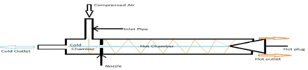
Ranque-Hilsch vortex tube is a device with no moving parts. When a highly pressurized stream of air is allowed to pass through its inlet nozzle the vortex is generated which produces two air streams namely hot and cold air stream. The cold air leaves from the outlet near the inlet nozzle and hot air in the opposite side. The fig. 1 shows the vortex tube. Vortex tube mainly consist of inlet nozzle form were the highly pressured air is passed. Vortex tube were the vortex is generated which separates the air in two streams namely hot and cold which are obtained at cold end nozzle and hot end nozzle. At the end of hot nozzle there is a nozzle cap which controls the mass flow rate of hot and cold air and is also adjustable. This movement of nozzle cap also affects the performance of vortex tube. Still many research is going on to determine the energy separation effect in the vortex tube.
The layout of a Vortex Tube
Fig. 1 Schematic of Vortex tube
_____________________________________________________________________________
1) Diffuser: Diffuser is the device that allows the high velocity air to expand and lowers the
temperature as well as pressure of the air. By the installation of a diffuser it affects the temperature of cold air.
2) Chamber: Chamber is portion of nozzle and facilities the tangential entry of high velocity air
stream into hot side. Generally the chambers noncircular form, but they are gradually converted into spiral form.
3)Cold air side: Cold side is cylindrical portion through which cold air is passed.
4)Valve: A device used for controlling the flow of fluid in the pipe or other enclosure. Control is by
means of a movable element that opens, shuts, or partially obstructs an opening in passage way. 5) Nozzle: A nozzle is a device designed to control the direction or characteristics of a fluid flow (especially to increase velocity) as it exists (or enters) an enclosed chamber or pipe.
6) Diaphragm: A diaphragm is a sheet of a semi flexible material anchored at its periphery and
most often round in shape. It serves either as a barrier between two chambers, moving slightly up into one chamber down into the other depending on the differences in pressure, or as a device that vibrates when certain frequency are applied to it.
7)Hot air side: Hot side is cylindrical in cross section and is of different length as per design.
IV.RESULTS AND DISCUSSION
N. Agrawal et al. [1]:- Fig. 1depicts the drop in cold end temperature of L/D 17.5 vortex tube using air as working medium at 3, 4 and 5 bar inlet pressure for varying cold mass fraction from 20% to 100%. It is shown that as pressure increase drop in cold end temperature increases up to 60% cold mass fraction and decreases further. The maximum drop in temperature is obtained at 5 bar pressure and 60% cold mass fraction i.e. 320C. This can be attributed to the fact that as
pressure increases it causes flow velocity to increase which is responsible for energy separation; also as cold mass fraction is increased beyond 60% some of the operating fluid in which energy separation has already occurred is also drawn at cold end. This causes mixing of hot and cold mass of working fluid which leads to net reduction in cold temperature drop. It can be seen that at 5 bar pressure the drop in cold end temperature is maximum for selected vortex tube of L/D ratio 17.5 i.e. capable of causing full expansion of the working medium air . However same trend is not observed for the 100% cold mass fraction i.e. drop in cold end temperature decreases which may cause the cold end temperature equal to inlet temperature causing drop in cold end temp to zero. Fig. 2 shows the drop in cold end temperature for different working mediums i.e. CO2 , nitrogen and
air by varying pressure from 2 bar to 5 bar for optimized vortex tube of L/D 12.5 and 17.5 respectively at constant cold mass fraction of 30%. The maximum drop in cold end temperature is observed for CO2 as working medium than air and nitrogen. At 4 bar pressure drop in cold end
temperature is 230 C for CO2, 180C for nitrogen and 200C for air. The maximum drop in
temperature is due to CO2 as working medium because of its high molecular weight and low gas
Fig. 1 Effect of pressure on cold end Fig. 2 Comparison of cold end temperature drop temperature drop of air, nitrogen and CO2
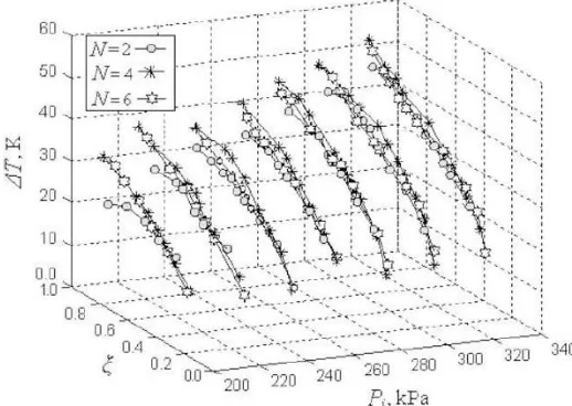
O.M. Kshirsagar et al. [2]:-Fig. 3 shows effect of 2, 4 and 6 nozzles on the performance of vortex tube, when the operating pressure and cold mass fraction is varied. As pressure is increased performance of vortex tube is also increased with 2, 4 and 6 nozzle. Performance also increase with increase in cold mass fraction up to 0.6 further which it decreases. Therefore best performance of vortex tube is obtained at high pressure, cold mass fraction of 0.6 and for vortex tube which has 4 nozzles.
Fig. 3 The variation of ΔT with Pi for different values of ξ, N = 2, 4, 6;
Fig. 4 shows the variation in the temperature difference with different values of inlet air pressure by varying cold mass fraction for 5mm cold orifice diameter and 300 hot valve angle on the tube’s performance which was experimentally studied. When fig, 4 is examined, it can be seen that the ΔT constantly increases from 200 kPa to 380 kPa for increase in cold mass fraction, but the increase is less significant between 380 kPa and 420 kPa for the geometry and dimensions of
_____________________________________________________________________________
Fig. 4 The variation of ΔT with Pi for different values of ξ, N = 4; d = 5mm and α = 30° for L.
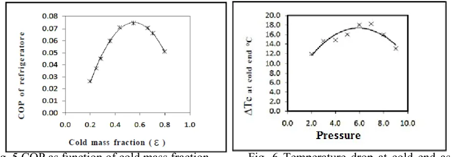
Gupta U. S. [3]:-Fig. 5 shows the plot of COP as function of cold mass fraction from 0.1 to 1 i.e. 10% to 100% at constant inlet pressure of 4 bar. It is shown that COP increases with increase in cold mass fraction up to 0.6 further which is decreases. Maximum COP obtained is 0.08 at cold mass fraction of 0.6. To have better results cold mass fraction should be set 0.6 or less than 0.6. Fig. 6 depicts the drop in cold end temperature of vortex tube with varying inlet pressure. It shows that drop in temperature at cold end increases linearly with increase in pressure. This may be due to stronger vortex which is created on the inner periphery of the tube due to increase in inlet pressure and the temperature separation is function of the inlet pressure and the exit pressure.
Fig. 5 COP as function of cold mass fraction Fig. 6 Temperature drop at cold end as at inlet pressure 4 bar function of inlet pressure.
V.CONCLUSION
From above study of literature it is observed that vortex tube performance increases with increase in pressure. As cold mass fraction increase, performance also increases but only up to 60% cold mass fraction above which it shows decreasing trend. Therefore, to obtain best performance cold mass fraction for vortex tube should lie within range of 20% to 60%. Among different working mediums i.e CO2, nitrogen and air best results are observed for CO2 as its molecular weight is higher than
Overall it is observed that at higher pressure, for cold mass fraction within range 20% to 60% and vortex tube with 4 nozzle gives best results for working medium having higher molecular weight, low gas constant and lower specific heat ratio.
REFERENCES:
1. N. Agrawal , S.S. Naik, Y.P. Gawale, “Experimental investigation of vortex tube using natural substances”, international Communications in Heat and Mass Transfer, Volume 52, 2014, 51–55
2. Kshirsagar O. M., Ankolekar V. V, Kapatkar V. N. Effect of Geometric Modifications on the Performance of Vortex Tube, Int. Journal of Engineering Research and Applications, Vol. 4, Issue 11(2014), 92-98.
3. Gupta U. S., Joshi M. K. And Pawar C.B. “Experimental Performance Evaluation of Counter Flow Vortex Tube”, Journal of Environmental Research And Development ,Vol. 7 No. 1A, July-September 2012
4. YunpengXue , MaziarArjomandi, Richard Kelso,” Energy analysis within a vortex tube”, Experimental Thermal and Fluid Science, Volume 52, 2014
5. Xingwei Liu, Zhongliang Liu,” Investigation of the energy separation effect and flow mechanism inside a vortex tube”, Applied Thermal Engineering, Volume 67, 2014.