Study and Analysis of the Gait and Legs Angle for
Hexapod on the Certain Trajectory Using Fuzzy
Logic Approach
Mohd Zamzuri Ab Rashid1 ,Hairol Nizam Mohd Shah 1 , Mohd Shahrieel Mohd Aras1, Anuar Mohd Kassim1
Rozaimi Ghazali1 ,Alias Khamis1 ,Marizan Sulaiman1 ,Esmail Ali Ali Alandoli1,Sayed Kushairi Sayed Nordin2
1 Faculty of Electrical Engineering, Universiti Teknikal Malaysia Melaka (UTeM), 76100 Durian Tunggal, Melaka, Malaysia2 Faculty of Manufacturing Engineering, Universiti Teknikal Malaysia Melaka (UTeM), 76100 Durian Tunggal, Melaka, Malaysia
Abstract— One of the features of hexapod is the ability of walking in different types of terrains. This paper is concerned with the pattern on how the hexapod walks on certain trajectory using tripod gait movement. In this project, a hexapod with two degree of freedom on each leg is designed and built for the purpose of legs angle research. The movement of the hexapod is guided by four Infrared Sensors (IR) installed which used to track the black line. Fuzzy Logic Controller (FLC) is applied to create better response of robot behavior than conventional controllers. The controller will be based on the signal input from Infrared Sensors (IR) to control the turning angle of the robot. Leg angle in 10°, 15°, 20° and 25° are tested and analyzed whether it can maneuver the given path successfully or not. In order to get accurate and reliable results, collection of data is programmed in Arduino microcontroller. The experimental data then are collected back to compare the performance of the robot with simulation conducted ealier.
Index Term— Hexapod Robot, Fuzzy Logic Controller, Trajectory
I. INTRODUCTION
Hexapod is the robot that belongs to the robot family that has six-legged and can move flexibly and stably on various terrains. The advantages of this robot is due to its high stability because it can stand stable in the static position with three or more legs[1]. This robot can be applied on many applications in real life such as search and rescue operations or environment exploration.
In this research, hexapod robot is built and analyzed on its legs angle via certain trajectory using tripod gait movement. The structure of hexapod is drawn and simulated using SolidWorks software. Since the hexapod robot in this project is travel on flat surface, the robot is built with two degree of freedom on each of its legs is sufficient to be used in this project. The motivation behind this project is due to disasters that occur globally i.e tsunami, earthquakes, storms and etc. Most of the natural disasters result in severe property damages or loss of life. The first things need to be done is to start searching and rescuing operations after the disaster. However, the rescue mission becomes extremely hard as the land covered with debris. Wheel vehicle can no longer be operated unless the debris are been cleared off. Different with wheel mobile robot, legged mobile robot can travel through these complex terrains with ease. Thus, using legged robot can
highly increase the efficiency of the rescue operations. Hexapod is chosen is because hexapod has the highest stability among all legged mobile robot. Compared with the wheeled robots, the legged robots such as hexapod have higher adaptability and stability to the surroundings especially to maneuver through uneven terrain. Different types of researches have been done to increase the overall performance of hexapod. However, the research on the angle analysis on hexapod legs has not been done in current research. In this project, the angle of the tripod gait movement during its turning motion on flat surface is mainly focuses.
The main objectives of this project are listed as follow, (i) to design and draft the hexapod using SolidWorks software, (ii) To develop a hexapod that can maneuver along a specified path and (iii) to study and analyze the different legs angle of hexapod when travel on certain trajectory.
II. MOTIVATION
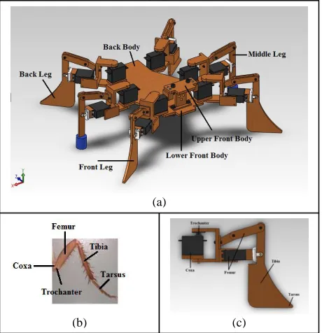
Various researches have been conducted previsouly about multilegged robot and one of the popular multilegged robot is a hexapod robot. According to [aa], hexapod can be grouped into two types which are rectangular and hexagonal. Rectangular hexapod has a rectangular body with three pairs of legs installed symmetrically on sides. Hexagonal hexapod has a round or hexagonal shape with legs distributed equally[2]. Another research focused on bionic mimicked hexapod robot. According to [3], natural structure has better function and higher adaptability to environment changes than the man-made mechanical equipment. In order to design a bionic hexapod, the model of insect can be referred to get the ideal mechanical structures[4]. The model of cockroaches is taken as an example. The cockroach's body has three primary regions - (i) the head, (ii) the thorax, (iii) the abdomen. All of its legs are attached at thorax region. The structure of legs can be divided into five main segments which are Coxa, Trochanter, Femur, Tibia and Tarsus[5].
whereas quadruped gait gives lower speeds[3]. Based on [7], in order for a robot to move forward using this type of gait, three out of six legs need to be lifted off from the ground and another three legs applied a backward force to achieve a forward movement.
The paper by [8] said that another factor that need to be focused in the hexapod robot is its legs working space optimization. When the hexapod robot moves, the overlapping of legs are often happened causing the working spaces of the hexapod limited especially for the rectangular hexapod while the hexagonal hexapod has small overlapping region of working spaces that can be ignored. In order to solve the overlapping problem of rectangular hexapod, the design of the body can be changed. By changing the shape of structure from rectangle to oval, the overlapping area decreases. The modified structure brings another benefit which is to improve the body's static stability due to the landing region of the legs of hexapod increases[8].
III. SYSTEM AND CONTROLLER DESIGN
System Design
The design that has been selected from the rough ideas then is drawn in detail using the Solidwork software. Fig.1 shows the design of the hexapod robot in this project. Fig.1(a) shows the isometric view of the robot while Fig.1(b) and Fig.1 (c) show the legs of the robot inspired from coacroach. In this research, the legs are designed to have five segments joint which are coxa, trochanter, femur, tibia and tarsus. However, middle legs have slightly differed compared to front legs and back legs in order to minimise the collision between the legs and then increase the working space of hexapod robot.
Experimental Setup
Fig.2 (a) to Fig. 2(d) show the view of the robot that has been realized and used for experimental study. Figure cc(a) is the isometric view, Figure cc(b) is the front view, Figure cc(c) is the side view and the last view of the robot is shown in Figure cc(d). The controller box is placed inside the robot’s centre body while the four infrared sensors are located in front of the robot as shown in the Figure cc(b).
Controller Design
This project utilizes Fuzzy Logic Controller (FLC) in order to control the movement of the robot. Fig.3 shows the FLC structure that is used in this project. There are four inputs to the fuzzy controller which are Left sensor, Middle Left Sensor, Middle Right Sensor and Right Sensor that are used to detect the black line.
Fig. 2. (c) Side View of the experimental robot. , (d) Top view of the robot.
Fig. 3. Fuzzy Logic Controller structure for the Hexapod robot movement
(b) (c)
(a)
Fig. 1 (a): Robot Design in Isometric view, (b) legs of the robot inspired from coacroach, (c) Legs of the robot design
(a) (b)
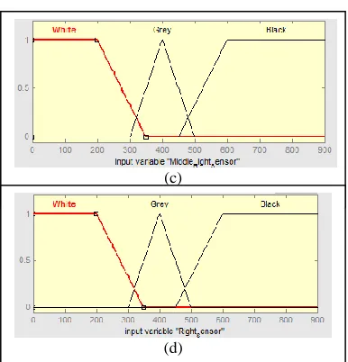
The membership functions are defined as White, Grey and Black with triangle shape for Grey and trapezoidal shape for White and Black as shown in Fig.4 (a) to Fig.4 (d). The range of the inputs is from 0nm to 900nm.
The output will determine which direction the hexapod should maneuver. There are five triangle shapes of membership functions in output which are left, slightleft, forward, slightright and right. The output membership function is shown in Figure ee.
From the output membership function in Figure 5, it can be said that forward means the robot is walking forward, Slight Left means the robot is turning slightly to the left, Slight Right means the robot is turning slightly to the right,Left means the robot is turn left in larger degree and finally Right means the robot is turn right in larger degree.
Walking Gait Selection and Setting
In this project, tripod gait is chosen due to its static stability and speed on flat surface. Fig.6 shows the position of legs of the hexapod whereas Table 1 displays Leg’s Numbering and Grouping of each leg. The reason behind of these legs numbers and grouping is to ensure smooth movement either in forward movement, turning left or turning right.
Group Number Leg Number
A 1 1, 7
B 2 2, 8
A 3 3, 9
B 4 4, 10
A 5 5, 11
B 6 6, 12
(a)
(b)
Fig. 4. (a) Input variable for left sensor, (b) Input variable for left middle sensor
(c)
(d)
Fig. 4. (a) Input variable for right middle sensor, (b) Input variable for right sensor
Fig. 6. Leg Numbering and legs group of Hexapod Robot
TABLE I.
LEG’S NUMBERING AND GROUPING Figure
Fig. 5. Output variable direction
Simulation for Forward Movement
In order for the robot to move forward, it consists of a total of seven steps. Firstly, it will raise up its Group A legs. Group B are
on the support phase. Second, Group A will move forward and
Group B will move backward at the same time. Third, Group A will
lower the legs. Fourth, Group B will raise the legs and Group A are
on support phase. Fifth, Group B will move forward and Group A
will move backward. Last, Group B will lower the legs. These steps
give a cycle of forward movement. All the forward movements are depicted in Fig.7.
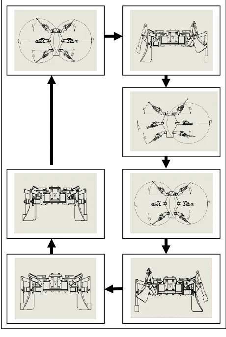
Simulation for Left Movement
For the robot to turn left, initially, legs Group B rise up. Second, leg 2 will move backward and leg 2 and 6 will move forward at the same moment. Third, Group B will lower the legs. Fourth, Group A raise the legs. Fifth, leg 2 will move forward and leg 4 and 6 move backward. Last, Group B will lower the legs. These steps form a cycle for hexapod to turn left is shown in Fig.8.
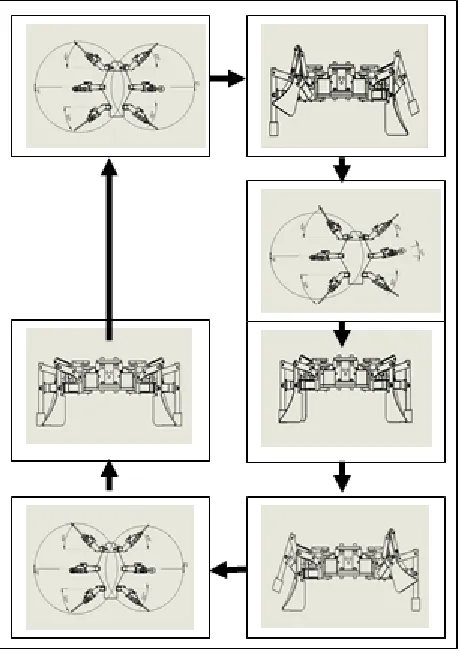
Right Movement
The robot can turn to its right position by following these seven steps.First, legs Group A rise up .Second, leg 1 and 3 will move forward and leg 5 will move backward at the same moment. Third, Group A will lower the legs. Fourth, Group B rises up the legs. Fifth, leg 1 and 3 will move backward and leg 5 moves forward. Last, Group B will lower the legs. These steps form a cycle for hexapod to turn right as shown in Fig.9.
IV. RESULTS AND DISCUSSION
Experimental Result for Hexapod Robot Movement
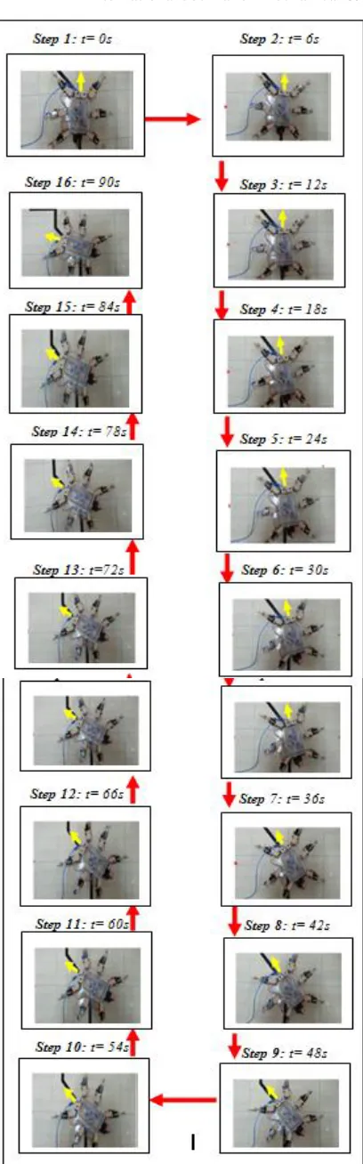
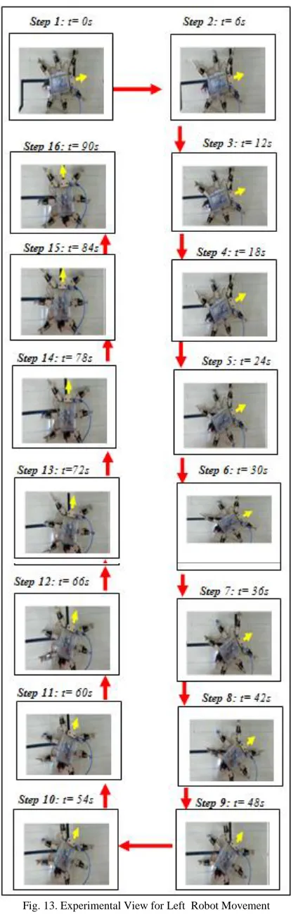
The Fig.10 – Fig.14 show the movement of hexapod walks at different track given. The angle for the legs during perform turning movement is adjusted to 15° in the following photos. There are 16 steps involved for each movements.
FLC Experimental Movement
The forward movement of the robot based on the robot’s locomotion and the output from the FLC controller are ilucidated in the Fig.10. For slight left movement of the robot it is shown in Fig.11.
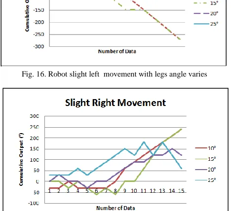
Fig.12 shows the slight right movement for the robot’s locomotion and FLC controller output.The left movement of the robot based on the robot’s locomotion and the output from the FLC controller are ilucidated in the Fig.13 The right movement of the robot based on the robot’s locomotion and the output from the FLC controller are ilucidated in the Fig.14.
In this experiment, there are four different legs angle which are 10°, 15°, 20° and 25° are adjusted and observed. For example, the angle of 10° means the hexapod will turn its legs in 10° away from its original legs position when it performs turning movement. A total of 15 data are collected for each movement. IR1, IR2, IR3, IR4, Output, Step and Cumulative Output means left sensor, middle left sensor, middle right sensor, right sensor, output value of defuzzification, number of turning steps taken and cumulative of output value respectively. The sensor right above the black lines will give higher value. The output value of defuzzification shows how much of the degree of the hexapod should turn.
Fig.15 to Fig.19 show the graph plotted for the robot movement with different legs angle adjusted. Figure 15 is the graph plotted for the cumulative angle output for legs adjusted at 10°, 15°, 20° and 25°.
Based on the data collected in different movement, in angle of 10° performs better in forward, slight left and slight right movement. For angle of 15° has better performance in turning left or right. In conclusion, the hexapod can turn left or right as expected. Although the hexapod walks in fluctuated line, it is still manage to walk according to the path given. However, the data can be varies based on different factors. First, the sensitivity of sensors will affect the overall performance of the hexapod such as the detection of different background colour. In this project, the hexapod works best on yellow background colour. Second is the alignment problem of the hexapod. This hexapod is built manually. Thus, the alignment during the fabrication will have some minor error which causes the hexapod unable to walk smoothly as expected. Third is the initial place of hexapod starts to walk. Each time when placing the hexapod, the distance and angle will be different which will cause data varies for each time measurement.
V. CONCLUSION
In conclusion, the objective of this project has been achieved. The design and simulation for the hexapod using SolidWorks helps to have a better viewing on how the model will behave and walk. The hexapod is successfully built and able to stand or walk stably. The experiment results shows that the hexapod able to follow according to the path given on the flat surface. The Fuzzy Logic Controller integrated inside the system enable the robot moves smoothly. It is recommended that based on the simulation and experimental studies, the Fig. 15. Robot forward movement with legs angle varies
Fig. 16. Robot slight left movement with legs angle varies
Fig. 18. Robot left right movement with legs angle varies
robot moves well using legs angle adjusted at 10° for forward, slight left and slight right movement. For turning left or right, legs angle adjusted at every 15° has better performance for the robot movement. Since this project focused on the hexapod walking on flat surface,it is suggested that the experiments can be further extended to ensure the robot can walk on the uneven surface and apply obstacle avoidance technique in the future.
REFERENCES
[1] D. Preumont, A. ; Alexandre, P. ; Ghuys, “Gait Analysis and Implementation of a Six Leg Walking Machine,” 1991, pp. 941 – 945 vol.2.
[2] X. Ding and Z. Wang, “Locomotion analysis of hexapod robot,” in in … and Walking Robots, 2010, pp. 291–311.
[3] B. Han, Q. Luo, Q. Wang, and X. Zhao, “A Research on Hexapod Walking Bio-robot’s Working Space and Flexibility,” in 2006 IEEE International Conference on Robotics and Biomimetics, 2006, pp. 813– 817.
[4] O. E. Lopez Botello, M. L. Balboa Garcia, P. del Carmen Zambrano Robledo, and A. R. Rivas Velazquez, “Design of a Hexapod Robot Based on Insects,” 2010 IEEE Electron. Robot. Automot. Mech. Conf., pp. 347– 354, Sep. 2010.
[5] T. V. Wilson, “How Cockroaches Work.” [Online].
Available:http://science.howstuffworks.com/zoology/insects-arachnids/cockroach1.htm. [Accessed: 06-Nov-2013].
[6] C. Al Lyman, “What Is a Gait Analysis?” [Online]. Available: http://www.active.com/running/articles/what-is-a-gait-analysis.
[Accessed: 08-Nov-2013].
[7] Z. Sakr and E. Petriu, “Hexapod robot locomotion using a fuzzy controller,” Robot. Sensors Environ. 2007. …, no. October, pp. 12–13, 2007.
[8] J. Zhanga, J. Wanga, W. Chena, and W. Chenb, “Virtual Model Optimization and Locomotion Control of Bionic Hexapod Robot,” in ieeexplore.ieee.org, 2011, pp. 497–501.
[11]S. Abd Rabbo, “Gait analysis and shaft synchronization of hexapod walking vehicle via fuzzy logic,” in 2010 7th International Multi- Conference on Systems, Signals and Devices, 2010, pp. 1–7.
[12]S. Lin and M. Chen, “A Fuzzy Controller for Hexapod Robot with Modified Fuzzy Identification,” 1996, pp. 1648–1654.
[13]Indika, “Difference Between Fuzzy Logic and Neural Network,” 2011. [Online]. Available: http://www.differencebetween.com/difference-between-fuzzy-logic-and-vs-neural-network/. [Accessed: 06-Nov-2013]. [14]G. Parker and Z. Lee, “Evolving neural networks for hexapod leg
controllers,” in Intelligent Robots and Systems, 2003.(IROS …, 2003, no. October.
[15] J. Ollervides, J. Orrante-Sakanassi, V. Santibanez, and A. Dzul, “Navigation Control System of Walking Hexapod Robot,” 2012 IEEE Ninth Electron. Robot. Automot. Mech. Conf., pp. 60–65, Nov. 2012. [16]J. Li, Y. Wang, and T. Wan, “Design of a hexapod robot,” 2012 2nd Int.
Conf. Consum. Electron. Commun. Networks, pp. 1768–1771, Apr. 2012. [17]J. Rajput and K. M. Hasarr, “Design and Implementation of a Hexapod
with 2-Degree-of- Freedom Legs and its Fuzzy-,” 2009, pp. 1–6. [18]“QRE1113 Line Sensor Breakout - Analog.” [Online]. Available:
http://dlnmh9ip6v2uc.cloudfront.net/datasheets/Sensors/Infrared/QRE111 3 Line Sensor Breakout - Analog.pdf. [Accessed: 15-Apr-2014]. [19]B. Kumar, “cockroach.” [Online]. Available:
http://www.weblearneng.com/cockroach. [Accessed: 09-Dec-2013].
ACKNOWLEDGMENT