The Analysis and Simulation of RF Micro
Cantilever Switch with Low Actuation Voltage
Using COMSOL Multiphysics Software
Mr. Dipta Dhal#1, Prof. M.K. Demde*2#
Department Of Electronics and Telecommunication, Priyadarshini College Of Engineering, Nagpur University
Abstract— The emerging phenomenon in wireless communication devices have shaped the requirement of micro devices having the inimitable capability of operating in the radio frequency (RF) range. RF MEMS switches have brought about a revolution in the already volatile area of nanotechnology due to the exceptional and extensive switching capability. The RF MEMS micro cantilever switches have been the basic building block of various enhanced MEMS devices. The various advantages of the RF MEMS switches also carry an area of concern due to the high actuation voltage required for operation. Lowering of this high actuation voltage by changing the mechanical and electrical characteristics of the switch is the theme for the simulation and analysis which in time has the potential to yield ubiquitous application of such devices in the field of Nano technology.
Keywords—RF MEMS, Micro cantilever switch, Actuation voltage, Beam, Electrode.
I. INTRODUCTION
The Micro-Electro-Mechanical Systems (MEMS) is a technology which deals with discrete operations of small sized but reliable devices such as sensors and switches. MEMS devices consist of tiny parts such as sensors, actuators and other tiny components for the development of the latest high speed small packaged effective systems. The MEMS are basically microstructures, which have capability of showing enhanced functioning abilities. New enhancements in the RF MEMS technology has paved way for brand new generations of RF connected devices and components such as the the RF MEMS switch [1]. Micro Electro Mechanical Systems (MEMS) is a reliable technology that in its most core and rudimentary form may be considered as miniaturized mechanical and electromechanical devices that are fabricated and developed by techniques of micro fabrication leading to the development of next-gen advanced sensing devices, cutting edge miniature remote sensing devices and highly intuitive biomedical devices [2], [3]. The physical features and dimensions of MEMS devices will vary from well below one micrometers on the lower end of the dimensional spectrum ranging up to several millimeters in range. MEMS devices exhibit more advanced features and characteristics which are more stable and efficient compared to the conventional semiconductor devices on every parameter such isolation, switching time, transition time, fidelity, RF power handling [4].
RF MEMS devices are very popular in the Nano scale range of products used in RF applications due to the noteworthy advantages and redeemable characteristics such as high isolation and low insertion losses [3]. The simulation of the switch includes meticulous material analysis for beam and anchor structure and the exhaustive simulation of the numerous changes in the beam structures which replicate the fundamental characteristics of the switches [4] .The concern of high actuation voltage comes as the sole disadvantage of the RF MEMS switches as compared to their solid state counterparts.
II. MICROMEMSCANTILEVER
“A cantilever is a simple beam supported by only one side of the beam on end”. The beam transmits the load to the support where it is resisted by moment and shear stress. Cantilever structure permits overhanging structures without external bracing. Cantilevers are the most common structures in the field of micro electro mechanical systems (MEMS) almost found in all MEMS devices. MEMS cantilevers are usually fabricated using materials like silicon (Si), silicon nitride (SiN). The fabrication technique typically involves undercutting the cantilever structure to release it and help in the functioning of the switch by bending in accordance to the force and voltage provided. MEMS cantilever has number of noteworthy applications [4], [5]. Many research groups are researching to develop cantilever arrays as biosensors for bio medical devices for more efficient bio medical applications. MEMS cantilever also have made a place in the radio frequency filters and resonators. In this paper we concentrate on MEMS cantilever in Switch and moreover to observe the various operations on the beam to lower the actuation voltage of the RF MEMS Switch [6].
, (1)
Where ν is Poisson's ratio, E is Young's modulus, L is the length of beam and t is the thickness of cantilever. Very sensitive optical and capacitive techniques have been developed to measure and calculate changes in the static deflection of cantilever beams used in dc coupled sensors [6].
The formula given below relating the cantilever spring constant K to the cantilever dimensions and material constants. The second is the formula relating the cantilever spring constant K to the cantilever dimensions and material constants which is mentioned below.
, (2)
Where qo is the uniformly distributed load over a length, lc of the beam. The principal benefit of MEMS cantilevers is their ease of fabrication in large arrays. The dispute of their actual implementation lies in the square and cubic dependences of cantilever performance specifications [6]. These linear dependences mean that cantilevers are quite sensitive to variation in process parameters and design attributes.
III.MICROCANTILEVERRFMEMSSWITCH
RF MEMS switches are micro machined devices that use a mechanical movement of beam to attain a short circuit or an open circuit condition within the RF transmission line. RF MEMS switches are classified by actuation technique (electrostatic, electro thermal, magnetic, piezoelectric), angle of deflection, circuit configuration (series, shunt), clamp configuration (cantilever, fixed-fixed beam), or contact interface (capacitive, ohmic). There are two main types of forces that can be used for the actuation of RF Switches: electromagnetic and electrostatic [7].
The characteristics of RF MEMS depend upon a number of Switching Parameters. Some important parameters to be taken care in the design of RF MEMS switches are [7]:
A. Transition Time
Transition time is defined as the time required for the output RF signal to rise from 10% to 90% for off to on transition and 90% to 10% for on-to-off transition. In a simple mechanical switch, the transition time is the time required for the moving contact to leave one stationary contact and strike the opposite stationary contact.
B. Switching Rate
The switching rate is the time required for the switch to respond at the output due to the change in control voltage. The switching rate, also referred to as switching speed, is always larger than the transmission time of switch.
C. RF Power Handling
RF power handling is a measure of how efficiently a switch passes the RF signal. This is usually given in terms of dB.
D. Insertion Loss
The insertion loss of an RF device is a measure of its efficiency for signal transmission. If the power transmitted to the load before insertion PT and the power received by the load after insertion is PR, after that the insertion loss in dB is given by 10 log10
(PT / PR).
E. Isolation:
The isolation of switching system is specified when there is no signal transmission. A major value (in decibels) indicates very small coupling between input and output terminals.
F. Linearity And Intermodulation:
G. Return Loss
The return loss of a switch mentioned to the RF loss reflected back by the device.
IV.THE MAIN OBJECTIVE IS TO FOCUS ON THE PHYRFMEMSSIMULATION
sical features, architectural characteristics and shape of the micro cantilever beam so that the voltage can be reduced and also to verify the various changes that occur due to variation in the applied force and voltage to realize and test the high performance of the efficient sophisticated switch [11]. The recommended structure composed of a substrate, two electrodes where one is pull down electrode [12].
In the simulation scheme, model of the switch has been designed. In this, a micro cantilever switch is designed with two electrodes. A substrate or base has been described initially, which is composed of the dielectric material. After the base is designed, then the two electrodes are placed above the substrate and after that a micro cantilever switch is realized with appropriate dimensions. The finite element diagnosis is completed for the modelling of the structure.
MEMS are designed by drawing individual 2-D layers, which when deformed on top of each one of them can create complex 3-D devices [13], [14]. Abundant tools from several technical fields are therefore being used for MEMS computer aided design (CAD). These tools extent from initial resolutions to advanced tools that incorporate finite-element designing, examination and layout support. The COMSOL multiphysics software is required in this case for modelling of the switch structure.
V. SIMULATIONOFSIMPLECANTILEVERSWITCH
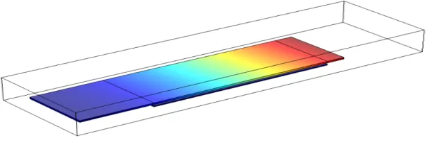
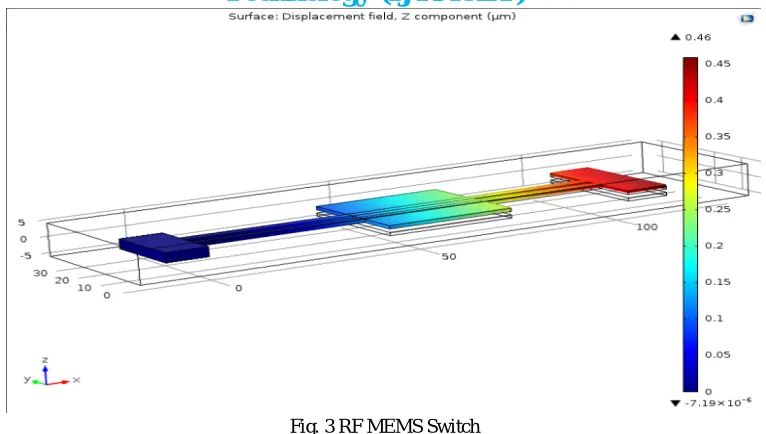
The MEMS switches are designed based on the mechanical movement to achieve the on and off transitions of switching state. The switch consists of a thin membrane suspended on the substrate and the anchor fixes one end and the other end is free. A simple schematic of such a switch is shown in Fig. 1. The switch is built on a thick-layer substrate. The cantilever beam of the switch consists of poly-silicon material. The cantilever beam is suspended above the substrate. When the voltage is applied between the beam and the substrate, the cantilever beam starts bending towards the substrate. When the beam gets deflected, the gap between the beam and substrate decreases [11], [14]. After the pull-in voltage, the beam gets connected with fixed electrode. The material used for the beam is poly-silicon and the substrate comprises of dielectric material. In this work, proposed model has large area. The proposed RF-MEMS series cantilever switch is as shown in Fig.1.
Fig. 1 Simulated Simple Cantilever Beam
[image:4.612.158.464.427.533.2]The cantilever switch is designed and simulated using Comsol Multyphysics simulation software. All the designs are made on micron scale in which the structure of the electrode is also altered to reduce the area of the electrode which is to be displaced so as to achieve the required displacement with low actuation voltage. The total displacement obtained is on par with the optimum level with lower actuation voltage.
Fig. 3 RF MEMS Switch
VI.SCOPEOFMEMSTECHNOLOGY
Today, Radio Frequency Micro Electro Mechanical System (RF MEMS) has been an attractive field for scientific research due to its promising application in future next-gen wireless communication and remote controlling & sensing system and extensive bio medical applications. RF MEMS components, such as RF MEMS resonators and oscillators, RF MEMS tunable inductors, RF MEMS switches, switched capacitors and varactors. The components and subsystems discussed here are based on RF MEMS switches. The main application areas of RF MEMS switches are:
A. Radar System for Defence Application: Phase shifters for satellite-based radars (20 billion cycles), missile systems
(0.1-1billion cycles), long range radars (20-200 billion cycles) [9].
B. Satellite Communication Systems: A satellite system would typically have 100’s of switches on-board integrate in the
form of switch matrices to provide system redundancy. The receiver input/output and low power switch matrices are typically implemented using coaxial switches while the high power switch matrix is implemented using waveguide switches [10].
C. Wireless Communication Systems: A RF MEMS technology has the potential of replacing many of the mechanical and
semiconductor switches used in mobile and wireless communication systems. RF MEMS switches and multiport RFMEMS would not only reduce size and power consumption, but also have superior performance.
D. Instrumentation Systems: These require high-performance switches, programmable attenuators, SPNT networks, and
phase shifters capable of at least 20-40 billion cycles and 10 years of operation, especially in industrial test benches.
VII. CONCLUSIONS
(NEMS), 2010 5th IEEE International Conference on, 2010, pp. 1-4.
[2] B. Peng, W.L. Zhang, G.H. Chen, W.X. Zhang, H.C. Jiang, Modeling microwave behaviors of series cantilever MEMS switch, Sensors and Actuators A 125 (2) (2006) 471–476.
[3] Maciel, John; Majumder, S.; Lampen, James; Guthy, Charles, “Rugged and reliable ohmic MEMS switches,” Microwave Symposium Digest (MTT), 2012 IEEE MTT-S International, vol., no., pp.1, 3, 17-22 June 2012.
[4] I.J. Cho, T. Song, S. H. Baek, and E. Yoon," A low-voltage and low-power RF MEMS series and shunt switches actuated by combination of electromagnetic and electrostatic forces," IEEE Trans. Microw. Theory Tech., vol. 53, no. 7, pp. 2450-2457, Jul. 2005.
[5] Gabriel M. Rebeiz, “RF MEMS: Theory, Design and Technology”, John Wiley & Sons Ltd, Chapters 1, 9 and 10, pp.1- 20, 259-324, 2003. [6] Sensors and Transducers, MEMS and Modern Technologies, International Frequency sensor association publishing (IFSA).
[7] Vijay K. Varadan, K. J. Vinoy, K. A. Jose, Pennsylvania State University, USA, “RF MEMS and Their Applications”, John Wiley & Sons. Inc., 2003. [8] S. Melle, F. Flourens, D. Dubuc, K. Grenier, P. Pons, F. Pressecq, J. Kuchenbecker, J. L. Muraro, L. Bary and R. Plana, “Reliability Overview of RF
MEMS Devicesand Circuits” in Proceeding of 33rd European Microwave Conference Held on March 2003. [9] Koen Van Caekenberghe, “RF MEMS Technology For Radar Sensors”, IEEE Trance 2009.
[10] S. K. Lahiri, H. Saha and A. Kundu, “RF MEMS SWITCH: An Overview at- A Glance”, in International Conference on Computers and Devices for Communication, 2009.
[11] Suryansh Arora, Sumati, Arti Arora, P.J George, “Design of MEMS based Microcantilever using Comsol Multiphysics”, Applied Engineering Research, Vol.7 No.11, 2012.
[12] Maziar Norouzi, Alireza K, “Design of Piezoelectric microcantilever Chemical Sensor in Comsol Multiphysics Area”, Electrical and Electronics, Vol.2, issue 1,No.184,2009.
[13] Koen Van Caekenberghe, “RF MEMS on the Radar”, in the IEEE Microwave Magazine, Oct.2009.