STATISTICAL COMPLEXION-BASED FILTERING FOR
REMOVAL OF IMPULSE NOISE IN COLOR IMAGES
1P.VENKATESAN, 2Dr.S.K.SRIVATSA
1
Senior Assistant Professor, Department of Electronics and Communication Engineering, SCSVMV University, Kanchipuram, Tamil Nadu, India.
2
Senior Professor, St. Joseph’s College of Engg, Jeppiaar Nagar, Chennai-600
E-mail: [email protected], [email protected]
ABSTRACT
A statistical complexion-based filtering techniques, named as the Adaptive Statistical Complexion based Filtering techniques (ASCF), is presented for removal of impulse noise in degraded color images. In distinction with the traditional noise detection techniques where only 1-D numerical information is used for noise detection and estimation, an innovative noise detection scheme is proposed based on statistical personality and features (i.e., the 2-D information) of the degraded pixel or the pixel region, leading to effective and efficient noise detection and estimation outcomes. A progressive restoration mechanism is devised using multipass nonlinear operations which adapt to the intensity and the types of the noise. widespread experiments conducted using a extensive range of test color images have shown that the ASCF is advanced to a number of existing well-known standard techniques, in terms of average image restoration performance criteria, including objective measurements, the visual image quality, and the computational complexity.
Keywords: color image restoration, impulse noise detection, progressive filtering.
1.
INTRODUCTIONImages are often corrupted by impulse noise due to a faculty image acquisition device or to channel transmission errors, much research has been done on removing such noise. The noise objective is to suppress the noise while preserving the integrity of edges and detail information. To this end, nonlinear methods have been found to provide more satisfactory results than linear techniques. The most frequently used nonlinear method it the median filter [Arc86], which is superior to linear filters in its ability to suppress impulse noise and preserve edges. Nonlinear filtering techniques have been extensively researched in the last decade due to their effectiveness in restoration of impulse noise degraded color images. The median filter is usually used to remove impulse noise. Compared with linear filters, the median filter is more powerful in that a single corrupt or noisy pixel in the filtering window will not affect the median value extensively. For removal of noise in color images, various vector median filters have proven relevant and effective. Amongst the early publications, the most well known vector filters for color image denoising include the vector median filter (VMF), the vector directional filter (VDF), and the directional distance filter (DDF). While these vector filters perform well in suppressing the
impulse noise, they introduce image distortions such as blurring around edges and in detail areas which feature high spatial frequency contents and variations. Different types of weighted nonlinear filtering techniques have been investigated over the years to achieve better performance in both noise suppression and detail preservation.
Recently, fuzzy filtering techniques have been developed, achieving powerful image denoising performance. A class of chromatic filters for image restoration in the color space was also proposed to achieve better chromatic smoothness. Adaptive filters have demonstrated their effectiveness in image restoration considering various types of noise with different distributions and image structures. In a sharp contrast with the additive noise that contaminates all image pixels, the impulse noise destroys only some portion of an image and leaves other pixels noise-free. Detection based vector filtering techniques such as the adaptive vector median filter (AVMF), the adaptive
vector LUM(lower-upper middle) smoother
ISSN: 1992-8645 www.jatit.org E-ISSN: 1817-3195
detection and switch between the output of an identity filter and that of a weighted median vector filter, according to the detection results. A survey of nonlinear vector filtering was presented in for impulse noise removal from color images.
2.
STATISTICAL MODELS OF IMPULSE NOISEColor images may be contaminated by various types of noise and impulse noise is the noise model frequently used and reported in digital restoration literature. Impulse noise corruption often occurs in digital image acquisition or transmission process as a result of photo-electronic sensor faults or channel bit errors. Image transmission noise may be caused by various sources, such as car ignition systems, industrial machines in the vicinity of the receiver, switching transients in power lines, lightning in the atmosphere and various unprotected switches. This type of transmission noise is often modeled as the impulse noise. The impulse noise can also be introduced into images during acquisition of the images. For example, the impulse noise may be introduced during fingerprint acquisition in real-life border security check. For more background information about the physical model of the impulse noise, we refer readers to. The two most common impulse noise types are fixed-value impulse noise (also known as the salt-and-pepper noise) and random-value impulse noise.
Let C = {c = (c1,c2) |1 ≤ c1 ≤ H,1≤ c2 ≤ W} denote
the set of the pixel coordinates of a color image, where H and W are height and the width of the image, respectively at each pixel coordinate c € C ,a multivariate value vector in the RGB color space, X(C) = [xR(c), xG(c), xB(c)]
T
, is used to represent the RGB(Red ,Green, Blue) pixels values.
Two approaches as reported in the literature are used in this paper to model the impulse noise for color image restoration. In the first approach, the impulse noise corruption of the color images in the RGB space is expressed by a multivariate model.
Y(c) = s(c), with probability (1-PI)
nT(c), with probability PI (1)
and in the second approach the impulse noise corruption of the color images in the RGB space is expressed by a multivariate model.
Y(c) = s(c), with probability (1-P)3
nt(c), with probability 1-(1-P)3
(2) Where S(c) and X(c) represent the original and the observed pixel (vector) values at coordinate c, respectively , and the value of nT(c) and nt(c) is
generated by substituting at least one color component of the pixel S(c) by distinct value ‘d’ in
both (1) and (2). In (1), PI is the impulse noise ratio;
a factor r=0.5 is used to simulate the channel correlation for each corrupted pixel, namely if at least one of the three components of the pixel is corrupted by the impulse noise, its remaining noise free components will have a 50% probability to be corrupted. The second approach (2) is a more generalized impulse noise model of color images where P = PR = PG = PB is the impulse noise ratio
for each channel of a corrupted color image, assuming that the image is corrupted by the impulse noise in a channel independent manner.
In (1) and (2) ,if d, the component value of nt(c) or
nT(c) equals the maximum or the minimum value of
the digital image (e.gg,, 255 or 0 for an 8- bit channel of the 24- bit color image in the RGB space), the impulse noise is referred to as the salt and pepper impulse . Each pixel of the image may be corrupted by either the pepper or salt impulse with unequal probabilities. However, if the amplitudes of the impulse are distributed randomly with, e.gg, the uniform or the Gaussian distribution, in the range of [0,255], a more general type of the impulse noise is generated and named as the random impulse noise.
The impulse noise can be represented by a joint probability distribution describing the spatial distribution of the impulses as well as their amplitudes. As is typically the case, these two quantities are considered to be independent. In this paper, an Adaptive Statistical Complexion based
Filtering techniques (ASCF) with a low
computational complexity is proposed for
optimized dimension and shape of processing windows .Computational efficiency of the ASCF is also investigated .Denoising performance of the ASCF is evaluated to demonstrate noticeable gains against that of a number of well-known benchmark techniques mentioned above, in terms of standard objective measurements perceptual image quality and computational complexity, especially for suppression of the impulse noise in medium-and large-size color images
3.
DIMENSIONAL AND GEOMETRIC FEATURESOFIMPULSENOISEA major problem in restoration of color images to date is the destruction of detailed image structures due to inability of denoising filters to distinguish a cluster of corrupted pixels from a cluster of pixels presenting fine (detailed) image structures and the incorrect removal or modification of pixel segments. This section describes a novel technique which detects and removes, effectively and efficiently, impulses in color images.
As defined in, any two pixels at (i1, j1) and
(i2, j2) are called 4-neighbors, if they have a city
block distance D4=1 from each other. Similarly, 8-neighbors are two pixels with a chessboard distance
D8=1. The city block distance is defined as D4 ((i1,
j1), (i2,j2)) = | i1 - i2 | + | j1- j2 | and the chessboard
distance is defined as D8 ( (i1, j1), (i2 ,j2) ) = Max {
i1-i2 | ,| j1- j2 |}. For example, each color image pixel
in fig.1(d) is represented by the coordinates of its position, i.e., a pair of integers (column number, row number ).given a pixel ( 3,3 ), for instance, its 4-neighbors are (2,3),(3,4),(3,2), and (4,3) and its 8-neighbors are its 4-8-neighbors plus (2,2),(4,4),(2,4) and (4,2).
Careful examination of a variety of color images corrupted by the fore mentioned impulse noise models reveals that most of uncorrupted pixels or pixel regions in a natural color image demonstrate a certain degree of smoothness. This means that the color intensities of a pixel always change gradually in all its 8-neighbors directions (e.g., in a smooth area), or change gradually at least in one (edge) direction (e.g., in a boundary area). In contrast with normal or uncorrupted pixels of images, impulse noise corrupted pixels always stand out as an isolate spot or a cluster by its very un-harmonious colors, shapes and sizes compared with those of its neighborhood. Even in the boundary (or edge) area, uncorrupted objects in natural color images have different types of edges from those corrupted by the impulses.
It is observed that almost all impulses only have sharp step edges and, in contrast almost none of the uncorrupted objects have this type of edges in its vicinity. The borders of the uncorrupted objects still have a narrow transitional region of a few pixels, even in the gradient direction of a sharp changing boundary area. In cases where images corrupted by the impulse with the low noise ratio, the sizes of the corrupted pixels (i.e., corrupted areas) are most likely represented by isolated individual pixels or a short line with one pixel width. The pixels of the line may be adjacent in the diagonal direction .with the increase of the noise ratio, corrupted pixel regions /clumps with two pixel width in two perpendicular directions may occur along with the individual impulses and smaller impulse regions as shown in images corrupted with the low impulse ratio. The shapes of the noise regions may be isolated point, a short thin line, a cross of two short thin lines or other small round shaped blocks. In other words, with the increase of the noise ratio, the noise may appear isolated or clustered with more different sizes and shapes.
According to the above observations and analysis of color, shapes and sizes of impulse noise corrupted pixels /regions, and the types of edges which form the borders of the noise regions, a novel impulse noise detection method is devised here based on 2 –D geometric features of the impulses, instead of the 1-D rank ordered statistical information used by other well know filtering techniques, to determine if each pixel in a color image is corrupted or cleaned. One of the geometric properties of the impulse noise is the edge feature of its boundary. An edge can be defined as a local discontinuity in color component or illumination intensity function and the edge orientation is defined as edges of an octagonally shaped object whose amplitude is higher or lower than its background. Therefore, the criteria for identifying the edge feature around the pixel are based on the two types of derivatives, which are approximated by pixel differences in digital color images.
Given that Y(c) = [ yR(c), yG(c), yB(c) ]T is the
vector containing color components functions of a color image, the two special types of partial derivatives are denoted as ∂Y(c)/∂ca and ∂Y(c)/∂cd
respectively. ∂Y(c)/∂ca at C= (i, j) is approximated
ISSN: 1992-8645 www.jatit.org E-ISSN: 1817-3195
S1a (n1a) = y [i.j]-y [i-n1a ,j]
S2a (n2a) = y [i,j]-y[i, j-n2a]
S3 a
(n3 a
) = y [i,j]-y[i+n3
a
,j]
S4 a(n4a ) = y [i,j]-y[i, j+n4a]
[3]
Where na = [n1 a ,n2 a ,n3 a ,n4 a
]T, nak > 0 and the
default value of nak is 1,for 1≤k≤4, and subscript
“T” represents the transpose operation.
When a derivative is only considered in the diagonal direction, ∂y(c)/∂cd is approximated by Gd, the difference between the pixel and its other 8-neighbors, for each component of the color component, and defined as follows:
G1d(n1d) = y[ i,j]-y[ i-n1d, j-n1d]
G2d(n2d) = y[ i,j]-y[ i+n2d, j-n2d]
G3 d
(n3 d
) = y[ i,j]-y[ i+n3
d
, j+n3 d
]
G4d(n4d) = y[ i,j]-y[ i-n4d, j+n4d]
[4]
Where nd = [n1 d
, n2 d
, n3 d
, n4 d
]T, nk d
> 0 and the default value of ndk is 1 , for 1≤k≤4. The two
special derivatives, Ga and Gd, will be used to
measure the edge feature (sharpness) and other geometric properties to determine whether center pixel at c = (i,j) is corrupted or not in the ASCF technique.
4.PRINCIPLEOFASCFTECHNIQUE
In detecting and removing impulse noise a filter may make three main types of mistakes. Type I error (miss) occurs when there is a corrupted pixel which the filter does not detect. Type II error (false alarm) happens when the filter detects an impulse noise pixel which is actually clean. When the filter removes an impulse noise and replaces it with a value determined by a certain restoration strategy, type III error (over – or under-correcting error) is defined as the difference between the resultant value after the restoration process and true pixel value as the noise -free pixel was.Different types of the so-called “switching” filters and fuzzy filtering techniques have been developed over the years, achieving good performance in both noise suppression and detail preservation. Similar to the other well-known benchmark techniques including the so-called “switching” filters. And fuzzy-based filtering techniques. The ASCF technique described in this section consists of two components, i.e., impulse detection and impulse removal. The novel criteria used by the ASCF for noisy pixel detection
are based on a combination of the 2-D edge, geometric and size features of the noisy pixel/region in the images. They depart from traditional noise detection techniques used by the other existing filters, which only use some properties of the edge of a noisy pixel are 1-D rank ordered statistical information around the noisy pixel. For example, multiple threshold framework and corruption detectors are used in based on statistical information about the neighborhood of each local pixel to locate impulse noise and to preserve clean pixels. Time-consuming multiple reference filtering and complex parameter training process highly limit the usage of these filters in real-time applications. The new criteria presented in this paper also depart from recently developed fuzzy impulse noise filtering techniques. For example, the fuzzy noise detection method is mainly based on calculation of fuzzy gradient values and fuzzy reasoning, and the fuzzy membership function representing the impulse noise is a simplification of the obtained noise histogram.
5. A TWO DIMENSIONAL IMPULSE NOISE DETECTION
A key component of the AGFF technique is a novel impulse detection scheme based on the 2-D geometric information of the corrupted pixels. First, we define the edge feature –identification threshold,
Te, which represents the value of a derivative to
distinguish the sharp step edges from other types of edges [3]. Since very short thin lines usually form impulse noise pixels, the length of a line is also used as a feature to distinguish a short noise line from a fine line in color images. The length
threshold, Tl, may be defined accordingly to the
noise ratio.
Second, in terms of the pixel coordinates of a color image, C, a set of corrupted pixels is defined as
S1 ={ c|(( Sa < (-Te ))^ (Sa <(=Te )))
V((Sa >Te )^ (Sa >Te )), ndk € Nd , nka =1
[5] For 1≤k≤4, Nd = {1, 2, 3… Tm}
Tm = (Tl +1)/2}
Where Tm is used to define corrupted pixel-sizes in
and its default value is 2. According to (5), IF the two partial derivatives Sa and Sd of a pixel have the same sign while their magnitude are greater than a preset threshold , when nka is 1 and nkd is 1
adjacent to each other in diagonal direction within the defined length of Tl. Third, a set of corrupted
pixels, which include individual impulse pixels, straight noise lines with one-pixel width the pixels of the lines being only 4-neighbors to each other within the defined length of, is defined as
S2 ={ c|(( Sa< (-Te ))^ (Sd <(=Te )))
V ((Ga >Te) ^ (G d
>Te)), n a
k € Na,, nk d
=1 [6] For 1≤k≤4, Na = {1, 2, 3… Tm}
Tm = (Tl +1)/2}
Where Tm is used to define corrupted pixel-sizes in
S1 and its default value is 2. According to (6) , IF
the two partial derivatives Sa and Sd of a pixel have the same sign while their magnitudes are
greater than a preset Threshold Te,, when nkd is 1
and nka is 1 or 2 or 3 Tm(its k components may
have different values), then the pixel belongs to S2. Next, a set of corrupted pixels is defined as the S3, which include noisy pixels/regions within 3-pixel width in any region except noisy pixels already in S1 and/or S2, i.e., c € S1US2.
If S ={ c|(( Sa < (-Te ))^ (Sd <(=Te )))
V((Sa >Te )^ (Sa >Te )), ndk € Nd , nka =L}
[7]
Where 1≤k≤ 4, L is 2 or 3, and the default value for
nd and na is 2. Thus, S3 can be represented as
S3 = S - (S1US2)
[8]
Where Tm=2 for S1 and S2 in (8). According to (8),
IF the two partial derivatives Sa and Sd of a pixel have the same sign while their magnitudes are greater than a preset threshold Te, when n
d k and
na k are 2 or 3 and the pixel is not in S1 or S2,
THEN the pixel belongs to S3.
Finally, according to observation and analysis of a variety of natural images corrupted with the impulse noise, a protrusive point in a border area with high possibility of being a corrupted pixel is defined as:
S4 = {c| (( Sak< (-Te ))^ (Sdv<(=Te )))
V ((\Sak >Te) ^ (Sak >Te)),
ndk = nak =ndv =, nva =1,
V K€ {y|y € N n ^ y≠ e}, e € Nn,
Nn = {1, 2, 3, 4}, (v=k)
^ (v € {2, 3} V v € {3, 4} V v € {4, 1}
[9]
Vv € {1, 2})}.
According to (9), IF the two partial derivatives Gd
and G d pixel have the same sign while their
magnitudes are greater than a preset threshold T e,
with the partial derivatives indexed by k containing only three out of the four distance settings, and the partial derivatives indexed by being either {2, 3} or {3, 4} or{4, 1} or {1, 2} and equal to k, when ndk,nak ,ndv and nva , , , and are 1, THEN the pixel
belongs to S 4 . Since an impulse noise ratio p 1 < ,
U1=1n S i c C, where n=4 , in the current design, T
e in (5) and (9) may be set at different values.
The strategy of the progressive restoration for the ASCF is, first, to restore corrupted individual pixels or noise regions of small size. If it made either Type II or Type III errors, it should not introduce any new impulse noise regions bigger than the existing ones. Then, further operations are carried out around large noise corrupted regions to restore areas of the images associated with noise regions of the considerable size reability In order to take the advantage of the median filter and to avoid the draw backs. (I.e causing a number of the aircrafts for the uncorrupted pixels)[9] a detection scheme is described in this section for use before the median filtering for the restoration, as a result, the proposed restoration method based on the restricted median can keep the image unchanged when the filter processing window moves across the uncorrupted image details.
Clearly, it may become expensive to perform a sort on pixels within a large rectangular window. If the width of processing window is larger than three, a modified median filter can be applied alternatively in the ASCF technique. The modified median will be based in the part of the pixels which from the out – line of the window or the noise- free pixels within the processing window (3), since part of the pixels inside the window may have been corrupted. The noisy central pixel and its corrupted eight neighborhood pixels, if detected, will be excluded from the set for the median filtering. The modified median filter increases the reliability of the restoration and reduces the computational cost, especially for removing impulses of high noise ratio. If the channel correlation, factor r, for each corrupted pixel as defined in (1), approaches I, the modified vector filtering is recommended
ISSN: 1992-8645 www.jatit.org E-ISSN: 1817-3195
[image:6.612.88.299.171.437.2]the AGFF can tolerate the estimation deviation of the noise ratios, the simple trapezoidal shape is chosen as the functions in the fuzzification process. The maximum method is used in defuzzification. The noise type of the salt-and-pepper can be determined by the values of s1 or s2.
Fig 1. Block Diagram Of ASCF
A design principle for the following operations, which are adapted to different noise ratios and types, is to use as small a size of the window and as less a number of the passes as possible, as long as the impulse noise can be removed (to ensure preserving image details as much as possible). The number of passes was determined for removal of a noise region based on the worst case scenario within the estimated maximal size of the noise region. The operations designed for removing impulses from different corrupted pixel sets in natural digital color images, are defined as follows.
Operation I Consists of a two-pass filtering to restore color images with a low noise ratio. In the
first pass, it restores impulse corrupted pixels in S2.
In the second pass, it restores impulse corrupted pixels in S1 .
Operation II Consists of Operation I and Operator D. The Operator D is designed to remove corrupted pixels in S4. Operation II is designed to
restore color images with a medium or high noise ratio.
Operation III Consists of two passes of Operation
I, Operator D and one-pass filtering to restore
pixels in S3. First, one-pass filtering of pixels in S3
is applied, which is followed by Operation I. The second pass includes Operator D which is followed by another Operation I. Operation III is designed to restore corrupted images with a high noise ratio.
Operation IV Consists of two passes of Operation
III and one-pass filtering of pixels in S3 to restore
color images with impulse of very high noise ratio. It applies Operation III and then restores impulse corrupted pixels in S3 where for in (7). Finally, it
repeats Operation
6. RESULTS OF THE IMPULSE NOISE FILTER.
Window sizes of 3×3, 5×5 and 7×7 are experimented. A plot between PSNR and percentage of impulse noise for this window size is drawn in Figure 3. The best results for higher percentages of the impulse noise, a larger widow seems to be more appropriate but this filter is less suitable for a high level of noise as there is a loss of image details. As the window size of 3×3 produces better results up to 20% impulse noise, this filter is meant to deal with low and middle percentages of the impulse noise. This level of noise is usually found in many practical applications. The performance of this filter is illustrated through a set of color images with the impulse noise of densities 10%, 15and 20%.
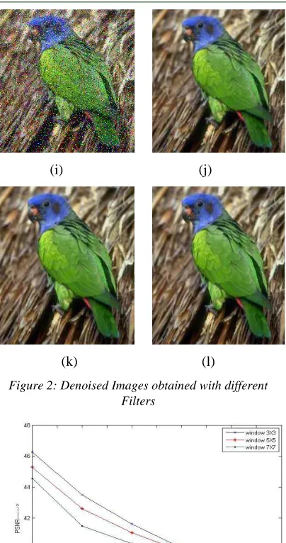
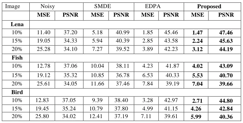
A comparative analysis of the proposed techniques is carried out with respect to two recent approaches in the literature, namely, SMDE method proposed by Pei-Eng Ng et al. [19] and Luo’s EDPA [20]. A sample set of the original images used in the experimentation are displayed in the values of MSE and PSNR enumerated in Table 1 for different experiments indicate that the proposed method is able to reduce more noise from the images while preserving almost all image details. The results are better than those reported in the literature as demonstrated by a higher value of PSNR in most of the images analyses. It can also be observed visually that the proposed filters are quite effective in noise reduction. The results of denoising obtained by a few existing methods in the literature are shown in Figure 2 including the results achieved by the proposed impulse filter for
Filtered Image
Average Fuzzy
Impulse
detection based
Fuzzy
peer
group
Noisy
Image
Filtering Stage
Impulse
Detection
comparative purposes. while input to each filter have the same level of noise (a) Lena Image with Impulse noise of density 15%, (b) Lena with FNRC, (c) Lena with NRFF, (d) Lena with Proposed, (e) Fish Image with Impulse noise of density 15%, (f) Fish with FNRC, (g) Fish with NRFF, (h) Fish with Proposed, (i) Bird Image with Impulse noise of density 15%, (j) Bird with FNRC, (k) Bird with NRFF, and (l) Bird with Proposed
method. A plot (See Figure 4) between PSNR and
percentage of Impulse noise for different methods proves this point for the Lena image
(a) (b)
(c) (d)
(e) (f)
(g) (h)
(i) (j)
[image:7.612.320.522.87.470.2]
(k) (l)
[image:7.612.87.531.137.730.2]Figure 2: Denoised Images obtained with different Filters
[image:7.612.90.298.240.728.2]Figure 3: PSNR vs. Window sizes for Impulse noise
ISSN: 1992-8645 www.jatit.org E-ISSN: 1817-3195
7. CONCLUSION
A statistical complexion-based filtering technique has been proposed for removing impulse noise from corrupted digital color images. The special contribution of the new filtering technique is its novel impulse detection method, which uses 2-D geometric features (shape and edge type) and the size of the impulse corrupted pixel/pixel region, instead of 1-D statistical information, to identify the impulse in an effective and efficient manner. The other novelty is its progressive adaptive restoration mechanism, where a carefully selected set of sizes and shapes of processing windows are employed, adapting to noise ratio and type to recover the corrupted pixels step by step through a reliable multipass process of low computational complexity This technique also provides a very reliable impulse noise type and ratio discrimination method. Through extensive experiment conducted using a wide range of natural color images, the proposed filtering technique has demonstrated superior performance to that of well-known benchmark techniques, in terms of standard objective measurements, visual image quality and the computational complexity, in removing the salt-and-pepper and the random impulse noise which
are commonly considered in color image
restoration. The technique is very useful for online applications to suppress impulse noise especially for medium and large sized color images. It can be further integrated with other benchmark techniques to suppress a mixed Gaussian and impulse noise contamination for color images to improve their performance
REFRENCES:
[1] I. Pitas and A. N. Venetsanopoulos, Nonlinear
Digital Filter: Principles and Applications.
Norwell, MA: Kluwer, 1990
[2] E. Abreu, M. Lighstone, S. K. Mitra, and K.
Arakawa, “A new efficient approach for the removal of impulse noise from highly corrupted images,” IEEE Trans. Image
Process., vol. 5, no. 6, pp. 1012–1025, Jun.
1996.
[3] V. I. Ponomaryov, “Real-time 2D-3D filtering
using order statistics based algorithms,” J.
Real-Time Image Process., vol. 1, no. 3,
pp.173–194, 2007
[4] X. Li, “On modeling interchannel dependency
for color image denoising,” Int. J. Imag. Syst.
Technol., vol. 1, no. 3, pp. 163–173, Oct.
2007.
[5] O. Lezoray, A. Elmoataz, and S. Bougleux,
“Graph regularization for color image
processing,” Comput. Vis. Image Understand., vol. 10, no. 1–2, pp. 38–55, Jul.–Aug. 2007.
[6] A. Elmoataz, O. Lezoray, and S. Bougleux,
“Nonlocal discrete regularization on weighted graphs: A framework for image and manifold processing,” IEEE Trans. Image Process., vol. 1, no. 7, pp. 1047–1060, Jul. 2008.
[7] P. E. Trahanias and A. N. Venetsanopoulos,
“Vector direction filter: A new class of multichannel image processing filter,” IEEE
Trans. Image Process., vol. 2, no. 10, pp. 528–
534, Oct. 1993
[8] D. G. Karakos and P. E. Trahanias,
“Combining vector median and vector
direction filters: The directional-distance
filter,” in Proc. IEEE Int. Conf. Image
Process., Washington, DC, Oct. 1995, vol. 1,
pp. 171–174.
[9] R. Lukac and K. N. Plataniotis, “A taxonomy
of color image filtering and enhancement solutions,” in Advances in Imaging and
Electron Physics, P. W. Hawkes, Ed. New
York: Elsevier, 2006, vol. 140, pp. 187– 264.
[10]V. Chatzis and I. Pitas, “Fuzzy scalar and
vector median filters based on fuzzy
distances,” IEEE Trans. Image Process., vol. 8, no. 5, pp. 731–734, May 1999.
[11]H. H. Tsai and P. T. Yu, “Genetic-based fuzzy
hybrid multichannel filters for color image restoration,” Fuzzy Sets Syst., vol. 114, pp. 203–224, 2000.
[12]R. Lukac, K. N. Plataniotis, B. Smolka, and A.
N. Venetsanopoulos, “cDNA microarray image
processing using fuzzy vector filtering
framework,” J. Fuzzy Sets Syst., vol. 152, no. 1, pp. 17–35, May 2005
[13]L. Khriji and M. Gabbouj, “Adaptive fuzzy
order statistic-rational hybrid filters in color image processing,” Fuzzy Sets Syst., vol. 128, no. 1, pp. 35–46, Mar. 2000.
[14]E. S. Hore, B. Qiu, and H. R. Wu, “Improved
color image vector filtering using fuzzy noise detection,” Opt. Eng., vol. 42, no. 6, pp. 1656–1664, Jun. 2003.
[15]A. C. Bovic, “Streaking in median filtered
images,” IEEE Trans. Acoustic., Speech,
Signal Process. vol. 35, pp. 493–503, Oct.
1985.
[16]B. Smolka, K. N. Plataniotis, and A. N.
Venetsanopoulos, “Nonlinear techniques for color image processing,” in Nonlinear Signal
Applications. Boca Raton, FL: CRC, Dec.
2003, pp. 445–505
[17]R. C. Gonzalez and R. E.Woods, Digital Image
Processing, 2nd ed. Englewood Cliffs, NJ:
Prentice-Hall, 2002.
[18]Y. Nie and K. E. Barner, “The fuzzy
transformation and its application in image processing,” IEEE Trans. Image Process., vol. 15, no. 4, pp. 910–927, Apr. 2006
[19]S. Schulte, V. D. Witte, M. Nachtegeal, D. V.
Weken, and E. E. Kerre, “Fuzzy two-step filter for impulse noise reduction from colour images,” IEEE Trans. Image Process., vol. 15, no. 11 pp. 3568–3579, Nov.2006.
[20]Z. Ma, H. R. Wu, and B. Qiu, “An structure
adaptive hybrid vector filter for the restoration of digital color images,” IEEE Trans. Image
Process., vol. 14, no. 12, pp. 1990–2001, Dec.
2005.
[21]Z. Ma, H. R. Wu, and D. Feng, “Fuzzy vector
ISSN: 1992-8645 www.jatit.org E-ISSN: 1817-3195
Table 1: Comparison Of Performance For Impulse Noise
Image Noisy SMDE EDPA Proposed
MSE PSNR MSE PSNR MSE PSNR MSE PSNR Lena
10% 11.40 37.20 5.18 40.99 1.85 45.46 1.47 47.46
15% 19.05 34.33 5.94 40.39 2.85 43.58 2.24 45.63
20% 25.28 34.10 7.27 39.52 3.89 42.23 3.12 44.19
Fish
10% 12.78 37.06 10.04 38.11 4.23 41.87 4.02 43.09
15% 19.12 35.32 10.85 36.78 6.53 40.33 5.53 40.70
20% 25.61 34.05 11.66 37.46 7.84 39.19 7.04 39.66
Bird
10% 12.83 37.05 9.39 38.40 3.28 42.97 2.71 44.80
15% 19.45 35.24 10.79 37.80 4.99 41.15 4.26 42.84