All-Optical EXOR for Cryptographic Application
Based on Spatial Solitons
Mario Marco Corbelli1, Fabio Garzia1,2, Roberto Cusani1
1Department of Information, Electronics and Telecommunication Engineering,
LA SAPIENZA, University of Rome, Rome, Italy
2Wessex Institute of Technology, Ashurst Lodge, Ashurst, Southampton, England
Email: [email protected]
Received March 9, 2013; revised April 9, 2013; accepted April 20, 2013
Copyright © 2013 Mario Marco Corbelli et al. This is an open access article distributed under the Creative Commons Attribution License, which permits unrestricted use, distribution, and reproduction in any medium, provided the original work is properly cited.
ABSTRACT
The purpose of this paper is to present an all-optical EXOR for cryptographic application based on spatial soliton beams. The device is based on the propagation and interactions properties of spatial soliton in a Kerr nonlinear material. The interaction force between parallel soliton beam is analyzed from the analytical point of view and an exact solution is presented.
Keywords: All-Optical EXOR; Cryptography; Spatial Solitons; All-Optical Device
1. Introduction
Spatial solitons are optical beams that propagate without changing their shape, thanks to the balance between nonlinear effect (self-focusing) and diffraction [1]. This balance effect has demonstrated to be stable in two-dim- ensional waveguides.
Propagation and interaction properties of spatial sol- itons are extremely interesting and useful in order to al- low and realize all-optical devices, thanks to their ro- bustness to the external disturbs. A plenty of all-optical devices have been proposed, such as filter [2], multi- plexer and demultiplexer, arithmetic and logical unit [3, 4], high velocity router [5].
In this paper an all-optical EXOR for cryptographic application is proposed. The device is based on two pe- culiar properties of spatial soliton: swing effect [6,7] and interaction between parallel soliton beams.
Swing effect represents an oscillating behavior of soliton beams that propagate in a non-constant transver- sal refractive index [6]. It has been demonstrated that soliton oscillations depends on the intensity of the soliton itself and on the shape of the transversal refractive index.
Another interesting property of spatial soliton is re- presented by the interaction force between two parallel propagating soliton due to the non-linear effects of the material. This force is an exponential function of the relative distance between solitons and a sinusoidal func- tion of their relative phase [8,9].
Unfortunately, nothing can be said about the coeffi- cients necessary to derive this force in an analytical way. Nevertheless an empirical method has been recently proposed [9] to derive a proper equation that could quan- tify the interaction force necessary to design all-optical devices.
Thanks to the numerical solution of this empirical for-mula it has been possible to propose different all-optical devices [5,9,10] whose correct behavior has been con- firmed by numerical simulations. In the present paper this empirical formula is used and a proper analytical solution has been found.
The proposed device can be used in cryptographic ap- plication since it represents a stream cipher that can be exploited either in ciphering or deciphering phase. The ciphered message is obtained by sending the message to be ciphered as a string of bits to the input to the device, together with the key string. The same key string can be used, on the same device in the receiving phase, together with the ciphered string, to obtain the original message (plaintext). Soliton beams represent the information me- dium and the processing activities (EXOR) is obtained thanks to the properties of soliton propagation and inter- action.
2. Structure of the Device
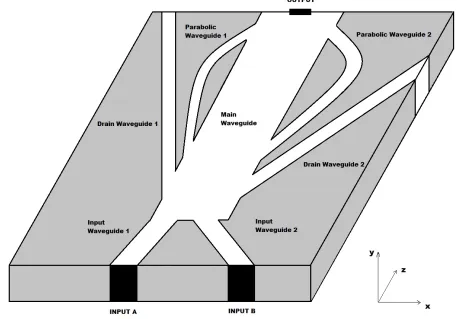
The device is composed by two inputs and one output, since it has to execute a logical EXOR operation. The complete scheme is shown in Figure 1.
It is composed by two input waveguides, a main wa- veguide, two drain waveguides and two parabolic wa- veguides. The waveguides are characterized by different geometries and different transversal refractive index pro- files: main waveguide is chosen to have a constant tr- ansversal refractive index profile whereas input wave- guides and parabolic waveguides are characterized by a triangular transversal refractive index profile.
The two inputs are labeled with letters A and B. If the device must be integrated, two proper laser diodes can be used to generate input pulses whose intensity is capable of generating spatial solitons in the material.
Input A is used to send the bit related to the message to be ciphered whereas input B is used to send the bit related to the cryptographic key. For simplicity, the two input pulses are supposed to be characterized by the same phase, without any loss of generality.
In the following it is illustrated how the proposed devi- ce performs the EXOR logical operation.
Since we deal with a passive device, if the two inputs
are equal to a logical zero (no input pulses are present), the output is equal to zero.
If input A is equal to a logical 1 (a pulse is present) and input B is equal to a logical 0 (no pulse is present), the pulse A generates a soliton that propagates in the input waveguide 1 following an oscillating path due to inclination and to the triangular transversal refractive index profile of waveguide 1 [2]. It enters the main wa- veguide with a certain transversal velocity (inclination) where it follows a linear trajectory, due to the absence of transversal refractive index profile, reaching the input of parabolic waveguide 2. Then it propagates inside this last waveguide, reaching the output of the device. The prop- erties of input waveguides and parabolic waveguides are illustrated in the following. At the moment, it is suffi- cient to know that, if the geometry and the transversal refractive index profile are correctly designed, the soliton beam is capable of reaching the output, performing an EXOR operation.
[image:2.595.67.524.400.719.2]If input A is equal to a logical 0 (no pulse is present) and input B is equal to a logical 1 (a pulse is present), pulse B generates a soliton that propagates in the input waveguide 2 following an oscillating path due to inclina- tion and to the triangular transversal refractive index pro- file of waveguide 2. The situation is similar to the previ-
ous one with the difference that the dissimilar inclination of waveguide 2, with respect to waveguide 1, induces a different phase variation on soliton B, with respect to soliton A, when it enters the main waveguide, This phase variations is properly controlled in the design phase, thanks to the different inclination of the input wave- guides, to allow a controlled interaction when two soliton beams are present, at the same time, in the main wa- veguide. This controlled interaction is illustrated in the following and allows to reaching the desired goal. After propagation in input waveguide 2, the soliton enters the main waveguide with a certain transversal velocity (in- clination) where it follows a linear trajectory, due to the absence of transversal refractive index profile, reaching the input of parabolic waveguide 1 where it propagates reaching, at the end of propagation, the output of the de- vice.
The last situation verifies when both inputs are equal to a logical 1. In this case solitons A and B propagates inside the related input waveguides, reaching the main waveguide with a converging trajectory. When they start to approach, they can experience an interaction force, and therefore acceleration, that can be attractive or repul- sive. It is well known [8,9] that they attract if their rela- tive phase is variable between 0 and π/2 and they repulse if their relative phase is variable between 3π/2 and 2π. If the geometry of input waveguides is designed on purpose, the two solitons experience a proper repulsive behavior that pushes them towards the inputs of lateral drain waveguides, where they are expelled by the device, without reaching the output. In this case a logical 0 in present at the output.
In this way it has been shown, from the qualitative point of view, the EXOR performance of the proposed device.
It has been said that soliton A could reach the output with a different relative phase with respect to soliton B. Since a cryptographic device is considered, this different phase between the two solitons could be detected by an eavesdropper in order to acquire significant information about the ciphering device, breaking its security. For this reason properly designed parabolic waveguides are used. These waveguides are characterized by different lengths so that solitons that propagate inside them are character- ized by the same phase when they reach their end, being undistinguishable when they approach the output.
It is now necessary to describe the device from the quantitative point of view.
3. Study of the Interaction Force between
Solitons
To correctly design the device, it is necessary to know exactly what happens when two parallel and close soliton beam propagate, influencing each other as in the main
waveguide of the device. It has already been said that they can experience a transversal attractive or repulsive force as a function of their relative phase. Until now it was not possible to have an analytical expression of this force. It is only possible to know that it is a cosinusoidal function of the relative phase and an exponential function of the relative distance [8,9].
In the present work an empirical formula [9] derived from Gordon theory and from numerical simulations is used to derive an analytical expression of the interaction force between parallel solitons. The derived formula al- lows to calculate the transversal acceleration as a func- tion of the relative phase and of the relative distance be- tween two parallel solitons.
Let’s consider two soliton beams that propagate along Z direction. It is well known [11] that the expression of a fundamental soliton in a Kerr material is given by:
02
2 0
1
, exp sech
2
n iZ X
E X Z
a n a a
0
(1)
where n0 is the linear refractive index, n2 the nonlinear
refractive index, β the wavenumber of the guided mode,
X the transversal coordinate, Z the longitudinal coordi- nate and a0 a parameter that is a function of the transver-
sal dimension of the beam.
If we set βX = x, βZ = z, A n n2 0 Q, 1 a0 C
and substitute in Equation (1) we obtain the normalized formula of the fundamental soliton, whose modulus is equal to:
sech
Q x C Cx
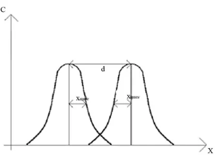
(2) In Figure 2 the schematization of the considered situ- ation of interaction between parallel solitons is shown.
Using this expression, the transversal acceleration bet- ween two parallel solitons, whose relative phase is equal to ϕ, is given by [9]:
2 2
2 d
exp 2 cos
d 5 HHHW
x z C x x z
z (3)
that is valid under the condition x ≥ 2xHHHW .
The parameter xHHHW (half height half width) repre- sents the distance from the center of the beam where the amplitude reduces to one half. It is possible to demon- strate that [9]:
1log 2 3 HHHW
x
C
(4) both HHHW
Since a dynamic analysis is used, the second derivative of x with respect to z is considered as a transversal acce- leration whereas the first derivative of x with respect to z is considered as a transversal velocity.
x and C are real positive.
Figure 2. Schematization of the considered situation of in-teraction between two parallel solitons.
time variable.
Equation (3) has already been used to design all-opti- cal device [9,10] even if from the numerical point of view.
In the present work, a proper analytical solution of Equation (3) is derived and the obtained solution is used to design part of the device whose correct behavior is demonstrated by the numerical simulations.
If we set c2 5cos
T and 2HHHW
x k, Equa- tion (3) can be written as:
2 2
d
exp d
x
T C k x
z (5)
Equation (5) represents a proper form of second order differential equation where the variable is represented by
x.
This equation can be transformed in a first order diff- erential equation since it is of the form x f x
.We can therefore write:
2
12
x
x f x F x c
(6) where F(x) is a primitive function of f(x) and c1 a proper
constant that depends of initial conditions.
In our situation f x
Texp
k x
and therefore
exp
F x T C C k x .
Substituting in Equation (6) and separating the varia- bles we have:
( ) 1
d
2d ec k x
x
z T
c C
(7)
that is an integrable expression whose solution is:
2 1
1 2
2 5
1ln sech 1
2 cos 2
HHHW
x z x
c C c z c
C
the integration constants c1 and c2 depend on the initial
conditions, represented by the relative velocity and rela- tive distance of the two solitons.
In particular c1 and c2 represents the solution of the
following system:
1 11
0 tanh
2 2
x c C c
c (9)
1 21 2
1 5 1
0 2 ln sech
2cos 2
HHHW
c
x x C
C c c
(10)
It is evident that c1 must be real positive.
The argument of logarithm is positive since we are int- erested in the situation where cos(ϕ) < 0 .
Let’s analyze now Equation (8) to verify if it correctly represents the considered situation. Since we are inter- ested at repulsive interaction π/2 < ϕ < 3π/2, two differ- ent situations can verify:
1) If the initial transversal velocity is equal to zero
x 0 0
and if the initial distance is quite short, the two solitons start to detach under the effect of the repul- sive force. The more they detach and the more the trans- versal acceleration decreases, as demonstrated by the exponential term of Equation (3), until reaching a limit value equal to zero. If we set in Equation (9) we obtain c2 = 0 and Equation (9) can be solved giving:
0 0x
1 2 exp
T
c C k
C
x0
(11) that is a real positive.
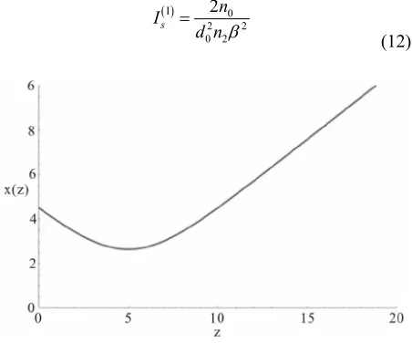
A graphical example is shown in Figure 3 where coh- erent values for C, k, x0 e ϕ, without taking care of their
physical meaning, have been used. The behavior of the obtained curve is coherent with what one could expect.
2) If the initial velocity is negative (that is the two so- litons are characterized by a convergent trajectory, as in the situation considered in our device), the relative dis- tance decreases until the exponential term of Equation (8) becomes significant. In this situation the repulsive force
[image:4.595.299.537.569.726.2](8)
decreases the approaching velocity until reducing it to zero and inverting it until reaching a value that is oppo- site with respect to the initial value.
In this situation, it is necessary to impose that both vel- ocity and initial position are different from zero: in this case the system represented by Equations (9) and (10) is not solvable in an analytical way. It is possible to dem-onstrate that the condition implies c2 < 0.
This is evident from Equation (9), since both C and c1
must be real positive.
0 0x
A graphical example is shown in Figure 4 where coh- erent values for C, k, x0 e ϕ without taking care of their
physical meaning have been used. The behavior of ob- tained curve is coherent with what one could expect.
The obtained analytical solution has been compared with the numerical result, confirming the correctness of the found theoretical solution found.
4. Design of the Device
4.1. Choice of the Material and Normalization After illustrating the theory necessary to understand the interaction of solitons in the main waveguide, it is possi- ble to start to design and dimension the device.
We first design the device in normalized units and su- ccessively in real units.
In the design all the physical restrictions are consi- dered. In this way the real device is immediately deriv- able from the normalized device.
The used normalization has already been shown prev- iously. It is very useful since it allows to transform path difference of solitons directly into phase difference be- tween the two solitons.
Given a certain material and a certain source chara- cterized by a given wavelength, the minimum value of intensity necessary to generate a fundamental soliton is [11]:
I 0 2 2 0 2
2 s
n I
d n
[image:5.595.62.288.531.719.2](12)
Figure 4. x(z) vs z for C = 1, ϕ= π, x0 = k, c2 = 5.
where d0 is the spot size of the beam whereas all the other
parameters have already been illustrated previously. It is also well known that the minimum value of inten-sity II
s
I necessary to generate a second order soliton is equal to twice I
s
I [11].
It is also possible to express the intensity of the soliton as a function of the normalized amplitude C [2]:
I 0 2
2
1 2 log 2 3 s
n
I C
n
(13) We choose, as material, a Schott Glass B270, whose optical parameters, at a wavelength λ0 = 620 nm, are n0 =
1.53 and 20 2 2 3.4 10 m W
n [12].
Further, we choose a spot size of laser beam equal to 10 μm.
Using Equation (12) it is possible to calculate the va- lues I
s
I e II
s
I .
Using Equation (13) it is possible to calculate the rela- ted values of I
s
I e II
s
I expressed in normalized am- plitude that are C(I) = 0.017 e C(II) = 0.034: the normalized
amplitude of the soliton beams used in the device must be variable between these two values to be sure to gener- ate a fundamental soliton.
We chose, for our design, C = 0.03.
It is now possible, from Equation (4), to calculate the half height half maximum width, that is equal to:
1
log 2 3 43.8986 HHHW
x
C
(14) It is now necessary to define the maximum variation Δn0 of the linear refractive index that characterizes the
transversal index profile of input waveguides and para-bolic waveguide. We choose, for our purpose, Δn0 = 10−2.
For practical realization reasons, it is necessary both the input waveguides and parabolic waveguides to be characterized by the same value of Δn0.
4.2. Design of Input Waveguides
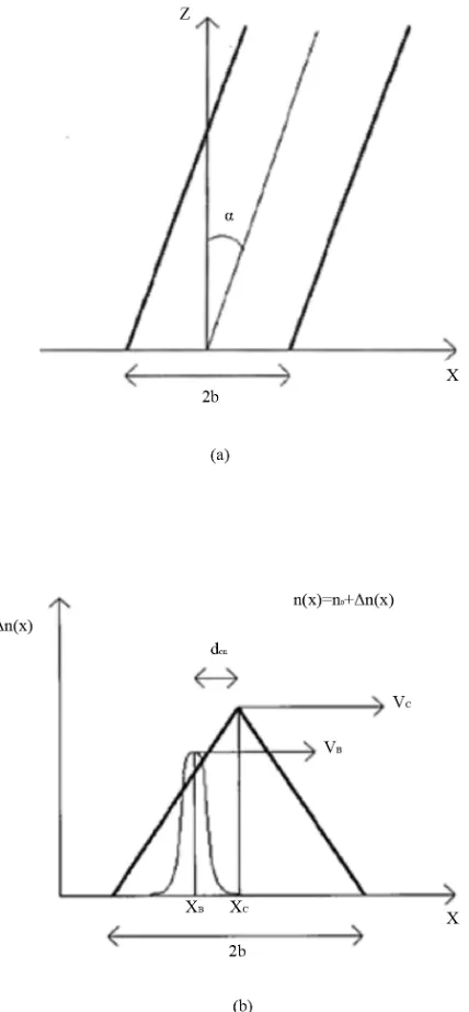
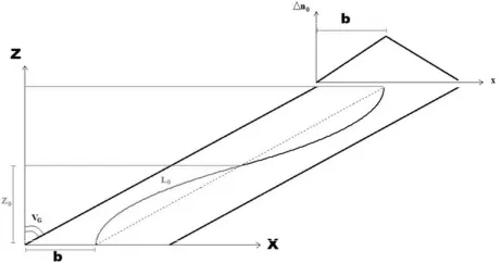
The two inputs waveguides are directly interfaced with input laser sources. They represent two oblique wave- guides, whose width is equal to 2b, characterized by dif- ferent longitudinal inclinations and by a transversal tri- angular refractive index profile, as shown in Figure 5.
The input waveguides must be designed such that the solitons inside them exit:
1) with a relative phase equal to π;
2) equal and opposite transversal velocities directed towards the center of the main waveguide where they interact in a controlled way, repelling each other.
Figure 5. Upper view of inclined input waveguides (a) and transversal view of the same waveguide together with a soliton beam, where position and transversal velocity of both waveguide and soliton are shown (b).
if a proper lock-in condition is respected:
0
2 G
v C
n
(15)
where vG represents the tangent of the inclination angle α between the longitudinal axes and waveguide axes, as shown in Figure 5.
Since C has already been defined, it imposes a restri- ction on vG. It is also necessary to remember that all the considered theory is valid under paraxial approximation
that imposes a certain limit (8˚ - 10˚) to the longitudinal propagation inclination of solitons.
Let xG be the position of the center of the waveguide. The local inclination of the waveguide with respect to z
axes can be regarded as the relative transversal velocity between the waveguide itself and the soliton that propa- gates inside it:
dtan d
G G
x z v
z
(16) It has been demonstrated that a soliton that propagates in a waveguide characterized by a triangular refractive index profile experience a transversal acceleration equal to [5,12]:
2 0 2 T
n
a C
b
(17) that remains constant until the soliton beam moves inside one of the lateral zone of the waveguide.
At the beginning of propagation the soliton beam is positioned in the centre of the waveguide. Since the waveguide seems to move transversally with respect to the soliton, the soliton itself enters the constant accelera- tion zone of the waveguide where its velocity grows linearly with z. If the lock-in condition is respected, the soliton is capable of reaching the center of the waveguide, crossing it and reaching the other zone of the waveguide where the negative acceleration decreases its transversal velocity until stopping it, reversing again its trajectory. It is clear that, if the lock-in condition is respected, the soliton propagates inside the waveguide following an oscillating path.
Let’s design now the waveguides.
If C = 0.003 then xHHHM = 43.8986. Equation (17) is valid only if HHHM. To respect this last condition we choose b = 200. Since have chosen Δn0 = 10−2, from
Equation (15) we can calculate the lock-in condition:
bx
0
2 0.
G
v C n 006 (18) If vG1 e vG2 are, respectively, the inclination of the first
and of the second waveguide with respect to z direction, we choose vG1 = 0.0025 e vG2 = 0.005. This choice satis-
fies the paraxial approximation. As it is possible to see, we have chosen an inclination of the second waveguide equal to twice the inclination of the first waveguide: this greatly simplifies the design of the device, as it is shown in the following.
We want now to describe the motion of the soliton ins- ide waveguide 1, where vG1 = 0.0025.
First of all, we want to calculate the longitudinal dist- ance Z01 that the soliton must propagate before reaching
the center of the waveguide. To calculate Z01 we have to
_
2 1
1 01 01 01
2 1 55555.5 2 G G T T v
v Z a Z Z
a
(19) To reach a longitudinal distance Z01 the soliton has
propagated along a parabolic path whose it is necessary to calculate the distance. Considering the first derivative of xB(z) with respect to z, we have:
2
1 d d
2
B T T
x a z x a z z
(20) and the elementary distance along the parabolic path with respect to x is equal to:
2 2 2
dl dx dz d 1z a zT 2
(21) Integrating Equation (21) we have:
01
01
2 2
01 d 0 1 d 55555.7869
Z T L
L
l
a z z(22) It is clear that it is necessary to design together the in-put waveguides such that the path difference (and there-fore the phase difference) of the two solitons that propa-gate inside them can reach the desired value which in-duces a repulsive action when the two solitons reach the center of the main waveguide.
In a similar way, we have for input waveguide 2:
_
2 2
2 02 02 02
2 1 111111.1 2 G G T T v
v Z a Z Z
a (23) 02 01 2 2
02 d 0 1 d 111112.9628
Z
T L
L
l
a z z(24) Let Z0 = Z02 = 2Z01. After this longitudinal distance the
soliton inside input waveguide 1 has made a complete oscillation, reaching again the center of the waveguide while the soliton inside waveguide 2 has made half os- cillation.
In Figure 6 the trajectory followed by a soliton in an oblique waveguide characterized by a triangular trans- versal refractive index profile is shown.
Due to the difference path followed, a relative phase difference Δ0 has generated. This phase difference can be
calculated by means of the difference of path, since the wavenumber β0 has been assumed to be equal to one in
the normalization operation. We therefore have:
0 L02 2L01 1.388 rad
(25)
Since a repulsive interaction in the center of the main waveguide is desired, the relative phase difference must be variable between π/2 e 3/2π. It is therefore necessary a longitudinal length of the two waveguides almost equal to twice Z0. Further, it is necessary the two solitons enter
[image:7.595.309.540.85.206.2]the main waveguide with opposite transversal velocities directed towards the center of the main waveguide. The choice made about the inclination of the two input
Figure 6. Trajectory followed by a soliton in an oblique waveguide characterized by a triangular transversal refrac-tive index profile.
waveguides (vG2 = 2vG1) allows to reach this goal if ZTOT
= 5Z01 = 277777.7 .
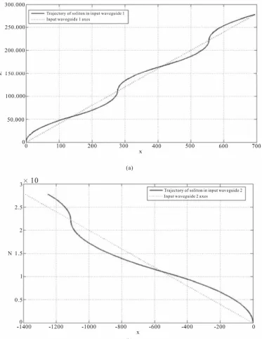
The trajectories followed by the solitons inside input waveguides are shown in Figure 7.
The obtained phase difference is equal to Δ = 2Δ0 =
2.777 rad.
When the two solitons reach z = ZTOT they are charac-terized by the same opposite velocity equal, in modulus, to vG2 = 2vG1 = 0.005. This behavior is due to the choice
of proper inclination (one twice the other) of the two input waveguides.
At the entrance of the main waveguide, soliton 1 is positioned in the center of waveguide whereas soliton 2 is shifted of a distance d with respect to the axes of the waveguide.
Due to the periodicity of motion, it is possible to ca- lculate d as the transversal distance between the center of the waveguide and the beam at z = Z01 since it is the
same distance at z = 5Z01:
01
012
2 01 01
1 138.889
2
G B
G T
d x Z x Z
v Z a Z
(26)
4.3. Design of the Main Waveguide
The design of the main waveguide is aimed at finding its width XG and the distances ZD and ZP where to position, respectively, the drain waveguides and the parabolic waveguides.
Figure 7. (a) Trajectory of soliton A inside input waveguide 1.(b) Trajectory of soliton B inside input waveguide 2. It is now possible to calculate ZP. Both the solitons
enter the main waveguide with an inclination with re- spect to the longitudinal distance equal to 0.005 and they must propagate along a distance equal to 938.889. Therefore we have:
938.889 187777.78 0.005
P
Z
(27) To calculate ZD it is necessary to study, from the ana- lytical point of view, Equation (3) related to the interact- tion force between two different solitons. We have de-
monstrated that this equation is solvable and we found the transversal distance x as a function of the longitudinal coordinate z. Since we have already designed the two input waveguides, we know the initial distance x0 and the
relative velocity v0 of the two solitons entering the main
waveguide.
This allows to calculating the two constant c1 e c2 of
Equation (8), solving the system composed by Equations (9) and (10).
Substituting the values x0 = 738.889 and v0 = −0.01 we
[image:8.595.113.486.86.568.2]1 0.0001000000368712
c (28)
2 53998.4715691338
c (29)
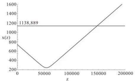
The behavior of xG(z) is shown in Figure 8.
The obtained behavior is coherent with what one could expect. It is possible to see that the relative distance be- tween the two solitons decreases linearly with z until the repulsive force becomes more intense due to the reduced relative distance. At this point they invert their motion and they start to detach with a velocity equal and oppo-site with respect to the initial velocity. Using Equation (3) we can solve the following (30) with respect to ZD:
D 1138.889x Z
(30) Thus we have the propagation distance ZD necessary to reach the side of mainwaveguide where it is possible to position the parabolic waveguides:
147996.936 D
Z (31)
For brevity, further details about drain waveguides are not given since they design is similar to the design of input waveguides. Their purpose is to take the single solitons away from the device, to avoid them to reach the output of the device, realizing the desired EXOR logical operation.
4.4. Design of Parabolic Waveguides
It is now necessary to design the parabolic waveguides. It has been shown that the input waveguides generate a relative phase difference between solitons equal to Δ = 2.777 rad. This phase difference is necessary to generate a repulsive reciprocal action when both solitons propa- gate inside the main waveguide, pushing them towards the drain waveguide and generating a logical 0 when both inputs are equal to 1.
[image:9.595.59.287.568.706.2]This phase difference is very critical when only single solitons propagate inside the main waveguide since it represents information about the input that generates
Figure 8. Behavior of relative distance between the two solitons in the main waveguide as a function of z.
the output which could be used by an eavesdropper to attack the device and discover the original enciphered message.
It is therefore necessary to use two different wave- guides that compensate the relative phase difference in- duced by the two input waveguides to let the single soli- tons coming from the inputs to reach the output of the device with the same phase, becoming indistinguishable from the phase point of view.
To reach this scope, two parabolic waveguides are used that must be correctly designed.
A parabolic waveguide has been chosen since it rep- resents the simpler curve that takes a soliton from an inclination that respects the paraxial approximation to an inclination with respect to the longitudinal axes equal to zero and vice versa. Further, parabolic trajectory is the one followed by a soliton that propagates inside a trian- gular refractive index profile waveguide.
The longitudinal parabolic waveguide has already been studied [13]. In the following we report only the significant parameters necessary to design the parabolic waveguide of the considered device.
In a longitudinal parabolic waveguide the position xG(z) of the central part of the waveguide as a function of z
coordinates is:
2 2 Gz d
x z z
a a
(32) where a is a real constant responsible for the curvature of the waveguide and d a real constant responsible for the position of the curve.
In a similar way to the oblique waveguide, a lock-in condition exists. This lock-in value is [13]:
1 2
0
1 D
d b C
a n
(33)
where b represents the half width of the triangular trans-versal refractive index profile. It is possible to demon-strate that the length of the curve expressed by Equation (32) (that is half of the total length of the whole wave- guide) is equal to:
2
2 2
2
2
4
2 2
4
log 8 4
8
log 4 G
L d d a
d
a d a d d
d
a a
a (34)
axial condition only in this last point:
0 2 tanh 8 0.14 Gd v
a
(35)
It is also well known that in this kind of waveguide the half of its longitudinal length can be calculated from its parameters a and d:
ˆ 2
Z
a d
(36) It is now possible to design both the parabolic wave- guides.
Let L1 and L2 be the length of parabolic waveguides 1
and 2 respectively. If Δ is the relative phase difference (and therefore the path difference since we are working with normalized units), if a compensation of the phase difference between the two solitons is desired (relative phase difference equal to zero), it is necessary that:
2 1
L L (37)
In our design process we decide to design the para-bolic waveguide 1 in an independent way with respect to the parabolic waveguide 2, choosing realistic values of the parameters and respecting Equation (33) and Equa-tion (35). After this choice it is possible to determine the length L1. Once determined L1 we impose the same value
ˆ
Z for waveguide 2 and we express the parameters a2
and d2 as a function of d1 by means of a proper parameter k:
2
d kd1 (38)
2 1 ˆ 2 Z a kd (39) At this point it is possible to calculate L2 as a function
of k and to solve the following equation:
2 1
L k L (40)
with respect to k. Once found the value k that satisfies Equation (40), it is possible to calculate the parameters a2
and d2 from Equations (38) and (39).
Finally it is necessary to verify that lock-in condition and paraxial approximation are respected in the calcu- lated waveguide 2.
The used process is heuristic and different attempts can be necessary before finding the optimal solution, since the respect of the paraxial condition can be verified only at the end of the calculation. It is anyway evident that if Zˆ increases (and therefore the parameters a of the waveguides increase), Equation (35) can be satisfied in an easier way.
Let’s apply the proposed method to the design of the longitudinal parabolic waveguides.
A proper value is Zˆ 700000 that allows to write:
1 1 2 2 350000 a d a d
(41) The width of the waveguides is equal to 2b*, being b*
equal to one half the width of the triangular transversal refractive index profile. In this case it has been chosen b* =
150, that is a different value with respect to the relative value of input waveguides and drain waveguides. Since it must be 2b* < d
1, we choose d1 = 500, obtaining, from
Equation (36), a1 = 15652.47584.
The length of the first parabolic waveguide can be calculated from Equation (34) obtaining L1 = 700000.952.
Given this value, using Equations (37)-(39) and the con-dition Δ = 2.77, it is possible to calculate the parameters of the second parabolic waveguide that are:
2 11126.54; 2 989.5; 2 700003.711
a d L (42)
Once calculated all the parameters, it is necessary to verify that the two parabolic waveguides respect the con-dition expressed by Equation (33) and Equation (35). Substituting the numerical values obtained for the two waveguides, with C = 0.03, Δn0 = 0.01 and b* = 150, we
have: 1 2 1 1 0 1 0.012 0.03 d b a n
(43)
1 2 2 2 0 1 0.026 0.03 d b a n
(44)
which demonstrate that the lock-in condition is satisfied. We also have:
1
1
0.014 0.07
d
a (45)
2
2
0.028 0.07
d
a (46)
which demonstrates that the paraxial approximation is satisfied.
To complete the design of the device it is necessary to calculate the distance from the end of the parabolic waveguides where it is necessary to position the output of the device itself. The two solitons, due to the feature of the parabolic waveguides, exit the waveguides them-selves with the same entrance inclination equal to v = 0.005. Since they have to cross a transversal distance equal to XG/2 to reach the center of the main waveguide, the related longitudinal distance where to position the output of the device is equal to:
5. Numerical Simulations
from the developed theory.It has therefore been shown that all the numerical simulations confirm the developed theory. The slight variation obtained with respect to the theory is due to other effects, such as the interface refractive index varia- tion between waveguides, and that have not been consid-ered in this paper for brevity.
To verify the correctness of the designed device, the dif- ferent operative conditions have been simulated using a FD-BPM algorithm and the results are compared with what one could expect from the developed theory.
In Figure 9 the numerical simulation when A = 1 and B = 0 is shown. It is possible to see that the soliton A, at the beginning remains confined into the input waveguide 1, where it propagates oscillating according to the theory. Once reached the exit of the input waveguide, the soliton enters the main waveguide. It propagates through it reaching the entrance of the parabolic waveguide where it propagates, changing its phase, until reaching again the main waveguide where it propagates reaching the output. The soliton experiences some slight refractive index pro- file variations when it leaves one waveguide and enter the next one, as it is possible to see in the numerical simulation. This refractive index variation has not been considered in the theory, for brevity, but they do not in- fluence in a significant way the functionality of the de- vice that behaves according to the theory.
The last simulation (A = 1, B = 1) is shown in Figure 11.
Numerical simulations were performed in normalized units.
6. Practical Considerations
To design the device from a physical point of view it is sufficient remember the normalization: βX = x, βZ = z. Inverting them properly and applying them to the values obtained in the normalized design phase, it is possible to have a real device.
Using the physical parameters related to the consid-ered material (Schott Glass B270), it is possible, by means of Equation (13), to calculate the intensity of the laser beam necessary to induce a soliton in the device: In Figure 10 the numerical simulation when A = 0 and
B = 1 is shown. Also in this situation the numerical simulation confirms the correctness of the design theory.
I 0 2 1
2 2
1 1.167565 10
2 log 2 3 s
n W
I C
n m
6
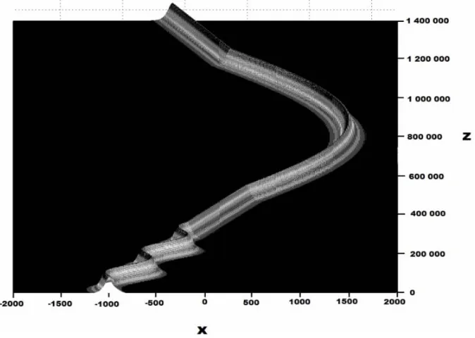
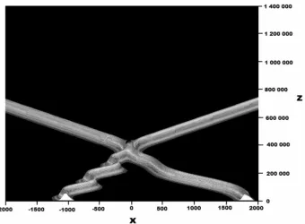
(48) In this case both solitons are present. It is possible to
see that they interact in a repulsive way when they meet at the center of the main waveguide, pushing each other towards the drain waveguides. In this situation the output of the device is equal to a logical 0 since the two solitons are not capable of reaching the output itself. Also this numerical simulation confirms what one could expect
This value ensures the generation of a fundamental soliton that follows the trajectories imposed by the de-sign phase since all the effects depended on the normal-ized amplitude C and therefore on its real intensity ex-pressed by Equation (48).
[image:11.595.131.468.478.718.2]We want now to do some considerations about the op-
Figure 10. Numerical simulation of the device when A = 0 and B = 1.
Figure 11. Numerical simulation of the device when A = 1 and B = 1.
erative velocity of the device. The main parameter that characterizes the computing time of the device is repre- sented by the response time of third order nonlinearities of the used material. The origin of these kinds of nonlin- earities, at the atomic level, is not quite clear [14]. In borosilicate glass, such as the considered Schott B270, the response time of Kerr effect is lesser than 10 ps [15].
[image:12.595.130.470.372.622.2]of the scope of the paper.
7. Conclusions
An all-optical EXOR for cryptographic application has been studied. Its working principle is based on the pro- pagation and interaction properties of spatial soliton beams.
The proposed device is composed by different kind of waveguides characterized by particular transversal re- fractive index profiles. The property of these waveguides was already known and they have been applied to our specific situation.
The novelty is represented by the study of interaction force between parallel propagating solitons where an analytical solution was found. This solution was applied to the interaction phase between two solitons in the main waveguide, allowing to correctly positioning the drain waveguides necessary to avoid the solitons to reaching the output of the device when both input are logical 1.
The proposed device can be used both in the ciphering and in dechipering phase. The computing time is limited, from the theoretical point of view, only by the response time of the third order nonlinearities of the material that, in our case is lesser that 10 ps.
The problem of the different relative phase of the two solitons that reach the output has been analyzed and solved, ensuring the two different solitons to reach the output with the same relative phase, becoming undistin- guishable to an eventual eavesdropper and guaranteeing a high level of security of the device.
REFERENCES
[1] R. Y. Ciao, E. Garmire and C. H. Townes, “Self-Trapping of Optical Beams,” Physical Review Letters, Vol. 13, No. 15, 1964, pp. 479-482. doi:10.1103/PhysRevLett.13.479 [2] F. Garzia, C. Sibilia and M. Bertolotti, “High Pass
Inten-sity Controlled Soliton Filter,” Optics Communications, Vol. 152, No. 1-3, 1998, pp. 153-160.
doi:10.1016/S0030-4018(98)00118-7
[3] C. S. Garzia and M. Bertolotti, “All-Optical Arithmetic Operations by Means of Spatial Soliton Interactions Prop-erties,” Institute of Physics Conference Series on Optical Computing, No. 139, Part IV, 1995, pp. 649-652. [4] Q. Wang, P. K. A. Wai, C. J. Chen and C. R. Menyuk,
“Numerical Modeling of Soliton-Dragging Logic Gates,”
Journal of the Optical Society of America B, Vol. 10, No. 11, 1993, pp. 2006-2029. doi:10.1364/JOSAB.10.002006 [5] F. Garzia, C. Sibilia and M. Bertolotti, “All-Optical Soli-ton Based Router,” Optics Communications, Vol. 168, No. 1, 1999, pp. 277-285.
doi:10.1016/S0030-4018(99)00306-5
[6] F. Garzia, C. Sibilia and M. Bertolotti, “Swing Effect on Spatial Soliton,” Optics Communications, Vol. 139, No. 4, 1997, pp. 193-198. doi:10.1016/S0030-4018(97)00128-4 [7] F. Garzia , A. Di Vito, C. Sibilia and M. Bertolotti, “Sw-
ing Effect of Spatial Soliton in Second Order Material,”
Optical and Quantum Electronics, Vol. 31, No. 9-10, 1999, pp. 1085-1092. doi:10.1023/A:1006916915874
[8] J. P. Gordon, “Interaction Forces Among Solitons in Op-tical Fibers,” Optics Letters, Vol. 8, No. 11, 1983, pp. 596-598. doi:10.1364/OL.8.000596
[9] F. Garzia, C. Sibilia and M. Bertolotti, “All-Optical Serial Switcher,” Optical and Quantum Electronics, Vol. 32, No. 6-8, 2000, pp. 781-798. doi:10.1023/A:1007062411351 [10] F. Garzia and M. Bertolotti, “All Optical Security Coded
Key,” Optical and Quantum Electronics, Vol. 33, No. 4-5, 2001, pp. 527-540. doi:10.1023/A:1010867522577 [11] J. S. Aitchison, A. M. Weiner, Y. Silverberg, M. K.
Oliver, J. L. Jackel , D. E. Leaird, E. M. Vogel and P. W. E. Smith, “Observation of Spatial Optical Solitons in a Nonlinear Glass Waveguide,” Optics Letters, Vol. 15, No. 9, 1990, pp. 471-473. doi:10.1364/OL.15.000471
[12] H. W. Chen and T. Liu, “Nonlinear Wave and Soliton Propagation in Media with Arbitrary Inhomogeneities,”
Physics of Fluids, Vol. 21, No. 3, 1978, pp. 471-478. doi:10.1063/1.862236
[13] F. Garzia, C. Sibilia and M. Bertolotti, “New Phase Mo- dulation Technique Based on Spatial Soliton Switching,”
IEEE Journal of Lightwave Technology, Vol. 19, No. 7, 2001, pp. 1036-1050. doi:10.1109/50.933300
[14] J. E. Aber, M. C. Newstein and B. A. Garetz, “Femto-second Optical Kerr Effect Measurements in Silicate Gla- sses,” Journal of the Optical Society of America B, Vol. 17, No. 1, 2000, pp. 210-127.
doi:10.1364/JOSAB.17.000120