ISSN 2250-3153
www.ijsrp.org
Particle Swarm Optimization Based Automatic
Generation Control of Two Area Interconnected Power
System
Kapil Garg*, Jaspreet Kaur**
*
Department of Electrical Engineering,YIET, Gadholi, Yamunanagar, Haryana, India
**
Department of Electrical Engineering,BBSBEC, Fatehgarh sahib, Punjab, India
Abstract- Due to the continuous change in load, the frequency and tie-line power of control areas get disturbed from their scheduled value which is undesirable. Automatic Generation Control (AGC) is an essential mechanism in electric power systems which balance generated power and demand in each control area in order to maintain the system frequency at nominal value and tie-line power at its scheduled value. This necessitates an accurate and fast acting controller to maintain constant nominal frequency. The limitations of conventional controllers i.e. Integral (I), Proportional Integral (PI) are slow and lack of efficiency in handling system errors. This paper proposes Particle Swarm Optimization (PSO) technique for AGC of two-area interconnected power system. Firstly, the conventional controllers i.e. Integral (I), Proportional Integral (PI) are used for AGC of two-area interconnected power system. Then PSO based controllers are used and various responses due to various controllers have been compared. The responses of the proposed methods are demonstrated by MATLAB simulations.
Index Terms- automatic generation control (AGC), conventional
integral (CI) and proportional integral (PI) controller, particle swarm optimization (PSO)
I. INTRODUCTION
hemain requirement in operation of interconnected power systems is the control of the frequency and the tie-line power flow. This can be achieved by the use of automatic generation control (AGC). The aim of the proposed controller is to restore the change in error to its nominal value in the smallest possible timewhenever there is any change in the loaddemand
etc.
This work presents the automatic generation control (AGC) of an interconnected two area system with the use of particle swarm optimization (PSO)technique. Here AGC for the two areas system is done by the use of conventional controllers andparticle swarm optimization (PSO)techniqueand change in overall error of the system is examined by using MATLAB SIMULINK.II. PROBLEM FORMULATION
We have taking the concept of area control error which is produced by comparing the feedback and reference signal and provide to particular controller which we used in the model of interconnected power system. So the problem formulate in automatic generation control is that we have first calculate the area control error by integral square error or by integral time absolute error techniques and then taking the gain of particular controller at which the system error reduced and frequency is
balanced according to load
.
III. PLANT MODEL DESCRIPTION
(A) LINEARIZED MODEL
Study of automatic generation control (AGC) problem of a large interconnected power system is necessitated by the importance of maintenance of frequency and tie line flows at their scheduled values. A large widespread electric power system can be divided into a large number of control areas interconnected by means of several tie lines.
The control objective is to regulate the frequency of each area and tie line power contracts simultaneously. As in the case of frequency regulation, proportional plus integral controller will be installed so as to give zero steady error in tie line power flow.It is conveniently assumed that each control area can be represented by an equivalent turbine, generator and governor system. In an isolated control area case the incremental power ∆PG-∆PD was accounted for by the rate of increase of stored kinetic energy and increase in area load caused by increase in frequency. Since a tie line transports power in or out of area, this fact must be accounted for the incremental power balance equation of each area.
ISSN 2250-3153
www.ijsrp.org MODEL OF TWO AREA INTERCONNECTED POWER SYSTEM
ΔPD1 Incremental load change in area 1
ΔPD2 Incremental load change in area 2
Ri Governor speed regulation parameter
Tsg Governor Speed time constant
Tt Turbine time constant
B1 Frequency bias constant for area 1
B2 Frequency bias constant for area 2
Tp 2H/ fD
Kp 1/D
D Load damping constant
Ki Integral gain
Δf1 Change in frequency for area 1
Δf2 Change in frequency for area 2
Let the step changes in loads ∆PD1(s) and ∆PD2(s) be
simultaneously applied in control areas 1 and 2, respectively. When steady conditions are reached, the output signals of all
integrating blocks will
become
constant and in order for thisto be so, their input signals must become zero
.
(B) CONVENTIONAL AGC SYSTEM
Automatic control system of close loop system means minimizing the area control error (ACE) to maintain system frequency and tie-line deviation are set at nominal value. Block diagram of two area system is shown in fig above. The ACE of each area is linear combination of biased frequency and tie-line error.
ACEi = Δptie,ijnj=1+ βi Δfi (1)
Where, 𝐴𝐶𝐸𝑖is the area control error of the 𝑖𝑡ℎ area
Δ𝑓𝑖 = frequency error of 𝑖𝑡ℎ area
Δ𝑝𝑡𝑖𝑒, = tie- line power flow error between 𝑖𝑡ℎ and 𝑗𝑡ℎ area
𝐵𝑖= frequency bias coefficient of 𝑖𝑡ℎ area.
IV. OPTIMIZATION OF CANTROLLER PARAMETERS, FRQUANCY BIAS FACTOR&
SPEED REGULATION CONSTANT
In this study we have considered all pi controller gains ie Ki1=Ki2=Ki,Kp1=Kp2=Kp,and frequency bias factors B1=B2=B and speed regulation constants R1=R2=R.we need to optimizeKi,Kp,B,R in order to obtain good dynamic response of the agc system. In this study Ki,Kp,B,R values are optimized using the particle swarm optimization technique by minimizing the quadratic performance index (PI) for 0.01 p.u. step load change in area-1 .where w1and w2 are the weight factor .
V. OVERVIEW OF PARICLE SWARM OPTIMIZATION
ISSN 2250-3153
www.ijsrp.org randomized assigned velocity. Among these particles, each
particle keeps track of its coordinates in the solution region which are associated with the best fitness it has achieved so far. This value is known as „pbest‟. Another „best‟ value that is tracked by the particle is the best value, obtained so far by any particle in the group of the particles. This best value is also known as a global best„gbest‟ and the pattern is forwards to successful solutions. PSO technique using equation (5) is known as the gbest structure. PSO is a population based EA that has many primitive benefits over other optimization techniques. A most attractive quality of the PSO approach is itssimplicity as it involves only two main reference equations. Each particle coordinates represent a possiblesolution assisted
with two real
vectors.
Each particle coordinates represent a possible solution assisted with two real vectors .And vi =[vi1, vi2, vi3...viN] are the two vectors assisted with each particle „i‟ in N-dimensional search space .Number of particles or possible solutions of a swarm can go forward through the feasible solution place to explore optimal solutions. Each particle modifies its position based on its own best exploration, and overall experience of best particles (Beielstein et al., 2003). This particle also considers its previous velocity vector according to the following reference equations,
Velocity modifications
Each particle velocity can be modified by the following equation:
Vi k+1
=C* (W*V1 k
+ C1rand x (pbesti – Si k
) + C2rand x (gbesti -
Sik)) (2)
Position modifications
Positions of the particles are modified at each interval of the flying time. The position of the particle may bechange or not change, depending on the solution value.
Sik+1 = Sik + Vik+1(3)
Where, vi is velocity of particle „i‟ at iteration k.
Vik+1= (W*V1k + C1rand x (pbesti – Sik) + C2rand x (gbesti -
Sik)) (4)
Typical values for the inertia parameter are in the range [0, 2]. On the other side several different approaches using a construction factor s, which increase the algorithm’s capability to converge to a better solution and the equation used to modify the particle’s velocity
Vi k+1
= s*(Vi k
+ C1rand x (pbesti – Si k
) + C2rand x (gbesti -
Sik))(5)
VI. PSO BASED CONTROLLER DESIGN
Step1.The minimum and maximum gain limits of PI controllers are specified from the conventional PI controller. The initial Particle matrix of(N X 8)is generated by selecting a value with a uniform probability over the search space (Kmin=0, Kmax=2).
Step2.Set the population size and the initial Particle velocities are set to zero.
Step3.Assume the initial value of K and enter the maximum no. Of iterations/generations required.
Step4.Evaluate the initial population by simulating the Load frequency Control block model with each particle row value as the PI controller gain value and calculate Performance index (ISE/ITAE) for each particle.
Step5.Initialize local minimum (Pbest) for each particle.
Step6.Find the best particle (Gbest) in initial particle matrix
based on the minimum performance index.
Step7. Start the iteration iter=1
Step8. Update the velocity of the particle using the equation shown below,
VelocityVik+1=C* (W*V1k + C1rand x (pbesti – Sik) + C2rand x
(gbest - Sik))
Where Constriction factor C=1 Cognitive parameter c1 =2 Social parameter c2 = 4-c1 Inertia weight
w
max- w
minw= w
max-
__________________ *iter
iter
maxISSN 2250-3153
www.ijsrp.org Step9. Create new particle from the updated velocity.
Step10. If any of the new Particles violate the search space limit then choose the particle and generate new values Within the particle search space.
Step11. Evaluate the performance index value for each new particle by simulating the LFC block model.
Step12.Update the best local position (Pbest) for each particle
based on the minimum value comparison between new Particle performance index and old Pbest performance index.
Step13. Update Gbest Global minimum particle and its
performance index.
step14.gen=gen+1
step15.If gen>maxgen go to step 7, otherwise go to next step.
step16.Print the global best PID controller gain values and its performance index value.
V11SIMULATION RESULT AND DISCUSSION
In this chapter different control strategies for supplementary control are implemented through MATLAB simulink model.
Integral (I) controller, Proportional Integral (PI) controllers,
and Particle Swarm Optimization (PSO) based controllers are implemented and the results are compared.
Case 1
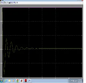
First we apply the integral control gains Ki1&Ki2 in pid controller in simulink model of two area interconnected power system and result waveform is shown in scope and study the variation of setlling time and overshoot time of load frequency control of area-1 & area-2 resp.as shown in fig 1&2 as well as tie line power is also studied and also show the variation in fig3.
Case 2
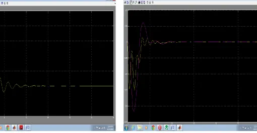
Secondly we apply the proportional integral control gains Kp1,Kp2 & Ki1,Ki2 in PID controller in simulink model of two area interconnected power system and same factor of load frequency control is studied and shown in fig.4&5 which shows that the settling time and overshoot time is reduced as compared to previous case of area-1 & area-2.also tie line power is compared as shown in fig.6
Case 3
Thirdly we apply the particle swarm optimization technique to automatically select and optimized the controller parameters through the number of populations of particle best and group best. And compared the result of both previous controller with this technique as shown in fig 7.also tie line power is observe and shown in fig . 8
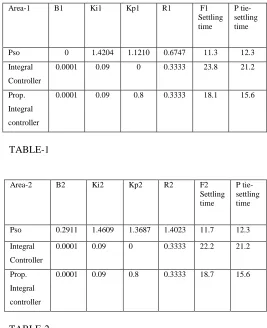
[image:4.612.315.582.64.392.2]And the reading of all considering parameter is tabulate in table 1&2 respectively.
[image:4.612.323.598.419.673.2]TABLE-1
TABLE-2
Fig1 Frequency deviation in area-1 of thermal reheats power system with integral controller
Area-1 B1 Ki1 Kp1 R1 F1
Settling time
P tie-settling time Pso 0 1.4204 1.1210 0.6747 11.3 12.3 Integral
Controller
0.0001 0.09 0 0.3333 23.8 21.2
Prop. Integral controller
0.0001 0.09 0.8 0.3333 18.1 15.6
Area-2 B2 Ki2 Kp2 R2 F2
Settling time
P tie-settling time Pso 0.2911 1.4609 1.3687 1.4023 11.7 12.3 Integral
Controller
0.0001 0.09 0 0.3333 22.2 21.2
Prop. Integral controller
ISSN 2250-3153
www.ijsrp.org Fig2 Frequency deviations in area-2 of thermal reheat power
[image:5.612.38.582.69.313.2]system with integral controller
[image:5.612.37.318.383.653.2]Fig 3 Tie line power deviation in two area interconnected thermal reheat power system with integral controller.
Fig 4 Frequency deviations in area-1 of thermal reheat power system with proportional integral controller
[image:5.612.323.598.383.654.2]ISSN 2250-3153
[image:6.612.79.589.59.324.2]www.ijsrp.org Fig 6 Tie line power deviation in two area interconnected
thermal reheat power system with proportional integral controller
Fig7 frequency deviation in area-1&2 of interconnected thermal reheat power system with PI controller with particle swarm optimization
VIIICONCLUSION
In the present work, a control scheme for AGC of two area
interconnected power system by using Particle Swarm
Optimization technique is implemented. It is clear from the
results that the performance of PI controller is better than I . In
case of PI with PSO controller settling time of frequency and
tie line power is smaller as compared to I and PI controller.
For a two-area power system various parameters are
calculated by PSO technique. The results show that the
performance of PSO based controllers is better than the
performance of conventional controllers. The peak overshoot
[image:6.612.322.597.67.322.2]andsettling time is reduced in case of PSO based controllers.
ISSN 2250-3153
www.ijsrp.org REFERENCES
(A) Naimul Hasan, Ibraheem and Shuaib Farooq, “ Real
time Simulation of Automatic Generation Control for
Interconnected Power System”, International Journal of
Electrical Engineering and Informatics,Vol. 4, Number
1,March 2012.
(B) Akanksha Sharma,K.P. Singh Parmar and Dr. S.K.
Gupta, “Automatic Generation Control of Multi Area
Power System using ANN Controller”, International Journal of Computer Science and
Telecommunication,Vol. 3,Issue 3,March 2012.
(C) AKHILESH SWARUP, “Automatic Generation Control
of Two Area Power System with and without SMES”,
International Journal of Engineering Science and
Technology,Vol. 3, no. 5,May 2011.
(D) Rajesh Joseph Abraham, D. Das and Amit Patra,
“Automatic Generation Control of Interconnected Power System with Capacitive Energy Storage”,
International Journal of Electrical and Electronics
Engineering 4:5,2010.
(E) K. S. S. Ramakrishna, Pawan Sharma and T. S. Bhatti,
“Automatic Generation Control of an Interconnected
Hydro-thermal system in Deregulated Environment
Considering Generation Rate Constraints”, International
Journal of Engineering Science and Technology,Vol. 2,
no. 5,2010,pp. 51-65.
(F) Panna Ram and A.N Jha, “Automatic Generation
Control of an Interconnected Power System with diverse
sources of Power Generation”, InternationalConference
on Industrial Electronics, Control and Robotics,2010.
(G) A.Soundarrajan,Dr. S.Sumathi and C.Sundar, “Particle
Swarm Optimization Based LFC and AVR of
Autonomous Power Generating System”, International
Journal of Computer Science,37:1,IJCS_37_1_10.
(H) Dr. K. Ramasudha,V.S. Vakula and R. Vijaya Shanthi,
“PSO based Design of Robust Controller for Two area
Load Frequency Control with Non Lineraties”,
International Journal of Engineering Science and
Technology,Vol. 2(5),2010,1311-1324.
(I) Gayadhar Panda, Sidhartha Panda and Cemal Ardil, “
Automatic Generation Control of Interconnected Power
System with Generartion Rate Constraints by Hybrid
Neuro Fuzzy Approach”, World Academy of Science
Engineering and Technology 52,2009.
(J) Lin Chen,Jin Zhong and Deqiang Gan,” “Optimal
Automatic Generation Control(AGC) Dispatching and
its Control Performance Analysis for the Distribution
Systems with DGs”, IEEE ,2007.
(K) R.Poli ,W.B. Langdon and O.Holland, “Extending
Particle Swarm Optimization via Genetic
Programming”,University of Essex,2005.
(L) J.Nanda and A. Mangla, “Automatic Generation Control
of Interconnected Hydro-thermal System using
Conventional Integral and Fuzzy Logic
Controller”,IEEE,2004.
(M)Hossein Shayeghi and Heidar Ali Shyanfar, “Automatic
Generation Control of an Interconnected Power System
using ANN Technique based on μ- Synthesis ”, Journal
of Electrical Engineering,Vol. 55, no.
11-12,2004,306-313
(N) José Luis Rodríguez-Amenedo, Santiago Arnalte, and
Juan Carlos Burgos, “Automatic Generation Control of
a Wind Farm with variable speed wind Turbines”, IEEE
Transactions On Energy Conversion, Vol. 17, no. 2,
June 2002.
(O) Hirotaka Yoshida, Kenichi Kawata, Yoshikazu
Fukuyam, Shinichi Takayama and Yosuke Nakanishi,
“A Particle Swarm Optimization for Reactive Power
and Voltage Control Considering Voltage Security
Assessment”. IEEE transactions on power systems, Vol.
ISSN 2250-3153
www.ijsrp.org (P) R. K. Green, “Transformed Automatic Generation
Control”, IEEE Transactions on Power System,Vol. 11,
no. 4,November 1996,P-1799-1804.
(Q) O.I. Elgerd and C.E.Fosha, “Optimum
megawatt-frequency control of multiarea electric energy systems”,
IEEE Trans. Power App. Syst., vol. PAS-89, no. 4, pp.
556–563, 1970.
(R) N. Jaleeli, D. N. Ewart, L. H. Fink, “ Understanding
automatic generation control”, IEEE Trans. Power Syst.
7(3) (1992) 1106-112
(S) S. K. Gupta, Power System Engineering (With
Computer Applications), Umesh Publications, New
Delhi 2009, pp. 313-327.
(T) B. R. Gupta, Generation of Electric Energy, Eurasia
publishing house LTD.2002. pp 279-296.
(U) S. H. Hosseini, A. H. Etemadi, “Adaptive Neuro-Fuzzy
Based Automatic Generation Control”, Science Direct,
Electric Power System Research 78 (2008) 1230-1239.
(V) J. Kennedy and R. Eberhart, “Particle swarm
optimization,” in Proc. IEEE Int. Conf.
NeuralNetworks, vol. IV, Perth, Australia, 1995,
pp.1942–1948.
(W)P. J. Angeline, “Using selection to improve particle
swarm optimization,” in Proc. IEEE Int. Conf. Evol.
Comput. Anchorage, AK, May 1998, pp. 84–89.
(X) D.P. Iracleous, A.T. Alexandridis, “A multitask
Automatic Generation Control for Power Regulation”,
Electrical Power System Research 73(2005) 275-285.
(Y) R. A. Krohling, H. Jaschek, and J. P. Rey, “Designing
PI/PID controller for a motion control system based on
Particle Swarm Optimization,” in Proc. 12thIEEE Int.
Symp. Intell. Contr., Istanbul, Turkey, July 1997, pp.
125–130.
AUTHORS
*Kapil Garg, M.Tech Scholar, Deptt. Of Electrical Engg. ,
BBSBEC,FATHEGARH SAHIB,PUNJAB, India
*Kapil Garg Asstt. Professor,Deptt. Of Electrical Engg. ,
YIET, Gadholi, Yamunanagar, Haryana, India
**Jaspreet Kaur Asstt. Professor, Deptt. Of Electrical Engg.,