867
MERGE BETWEEN CYCLIC PREFIX AND TRAINING
SEQUENCE FOR CFO ESTIMATION TECHNIQUES ON
OFDM SYSTEMS
GHASSAN MUSLIM HASSAN1, KHAIRUL AZMI ABU BAKAR2 MOHD ROSMADI MOKHTAR3
1 College of Science, Computer Department, Al-Mustansiriyah University, Baghdad, Iraq
2, 3 Faculty of Information Science & Technology, UKM, Bangi, Malaysia
E-mail: 1[email protected], 1[email protected], 2[email protected], 3[email protected]
ABSTRACT
Synchronization is the essential process between the transmitter and the receiver of wireless communication system, such as orthogonal frequency division multiplexing. Two essential factors, namely, carrier frequency offset (CFO) and symbol timing offset (STO) are related to synchronization. Each factor has several methods for solving the problems from synchronization in the time and the frequency domain. In this study, the work is performed in the time domain that handles CFO effect. It uses two techniques, namely, a training sequence and a cyclic prefix. Each technique hasadvantages and disadvantages. The proposed method uses a hybrid of these two techniques for CFO estimation. Simulation results corroborate that the proposed method has the combined benefits of both methods. The signal-to-noise ratio is used as the indicator. It plays substantial role with respect to bit error rate by transitioning from one technique to another as shown in the research results. MATLAB is used to set all simulation results.
Keywords:OFDM, carrier frequency offset, Training Sequence, cyclic prefix.
1. INTRODUCTION
OFDM is used in digital audio broadcasting (DAB), digital video broadcasting (DVB), wireless local area networks (WLAN), WiMAX, IEEE 802.11, IEEE 802.16, fourth-generation cellular systems, ultra-wideband (UWB), and long-term evolution (LTE) [1],[2],[3].
When the transmitter sends N-points of the fast Fourier transform (FFT), the receiver must receive these N- points without any data loss. Therefore, these N- points of orthogonal frequency division multiplexing (OFDM) symbols should be perfectly synchronized to find the beginning of each symbol. In the transmission side, a guard band known as a cyclic prefix (CP) is added to each OFDM symbol to prevent inter-symbol interference (ISI). At the receiver side, the CP is removed from the symbol to get these N- points. This removal which can be performed in the time domain (TD) or frequency domain (FD). The effect of the cansynchronization depends on the value of the carrier frequency offset (CFO). The receiving
symbols experience inter-carrier interference (ICI) due to this factor [4]. Moreover, OFDM is sensitive to the frequency and time synchronization. A primary factor that affects OFDM is the CFO [5] thereby leading to ICI.
One cause of the CFO is the frequency mismatch between the local oscillators of the receiver and the transmitter. Another cause is the Doppler effect in mobile communication (motion between the receiver and the transmitter) [6, 7]. Integral CFO (ICFO) and fractional CFO (FCFO) are two parts of the normalized CFO, where the total CFO is equal to ICFO and FCFO. In the receiver, as a cause of IFO, the sent signal has a cyclic shift as a value of CFO, thereby changing the subcarriers. Unless the cyclic shift is recomensed, the performance of bit error rate (BER) degrades. However, the orthogonality among the frequency components of the subcarrier is not destroyed. [7].
868 ICI effects. As such, the frequency component of a subcarrier should not be affected by another subcarrier [8]. Otherwise, the performance of the OFDM will degrade. Many techniques have been introduced and developed in the FD and TD to estimate the CFO. The aim of each technique is to decrease or eliminate the CFO. ICI occurs at the receiver when CFO is not estimated. As long as an amount of a CFO exists, the transmission performance reduced [9].
In communication system, BER refers to the performance in the receiver side. This performance may be affected by noise, interference, distortion, and wireless multipath fading. The quality of the channel is measured by using signal-to-noise ratio (SNR) (SNR may be negative or positive). The higher the SNR, the better the BER.
CFO has many estimation techniques and they can be divided into two types, namely, TD and FD. TD techniques are used for the training sequence (TS) and the CP, whereas FD techniques persume that the ideal synchronization has been done. The SNR was degraded due to CFO; at the same time, BER was increased, thereby requiring an estimation technique [10].
This paper is organized as follows. In Section 2, the literature review of the CFO in OFDM is discussed. In Section 3, the effects of CFO on the transmitted signal are reported. In Section 4, CFO estimation in TD and FD is performed using some techniques. In Section 5, the proposed method of merging CP and TS is presented. Finally, in Section 6, provides the conclusion of this work is provided.
2. LITERATURE REVIEW
The estimation of the frequency offset was proposed initially by Moose [11]. This estimation uses two matching symbols of OFDM that are sequentially transmitted to calculate the frequency offset of the subcarrier. Nevertheless, the estimated range of this technique is less than half the subcarrier spacing.
Classen and Myer [12] worked in this field and proposed a new technique on the basis of pilot tones. Each symbol of OFDM is placed in the FD and sent for CFO tracking. The synchronization method is divided into two phases, namely,
acquisition and tracking. In the acquisition phase, the coarse estimate of the frequency offset was obtained and corrected, while in the tracking phase, the remaining small deviations are corrected.
In the TD, rapid synchronization was used by Schmidl and Cox [13] with simplified computation for the CFO acquisition. This technique needs two symbols for synchronization.
The authors in [14] presented an integer CFO estimation method for OFDM systems. Two suitably Zadoff-Chu (ZC) sequences were chosen for training block to minimize the sensitivity to integer CFOs. To accommodate a convinced maximum CFO, the authors presented the principle for selecting the root index of the ZC sequence. The detection test of the training block was also presented to improve the dependency of the multi-path channel shape and the CFO. The technique performs well.
The authors in [15] enhanced the estimation of the frequency offset on the basis of complex TS. This technique was done in the FD by integer frequency offset and in the TD by fractional frequency offset. The comparison was done with the conventional Moose and Schmidl algorithms.
A new estimation approach for CFO in OFDM was presented in [16]. This new approach works in the FD and is recognized by its low complexity. The results corroborate that this new approach outperforms traditional methods on the low values of SNR.
The proposed method in [17] is based on CFO estimation in OFDM as a square eigenvalue problem. By using the predetermined type of modulation, that is, coding, this method was tested. It depended on recognizing training data and was examined with Classen estimator, maximum likelihood Moose estimator, CP-based estimator, and Cramér-Rao Lower Bound. The results affirm that the proposed estimator has high accuracy for most values of SNRs.
In [18], a previous study proposed a novel method for CFO estimation in OFDM systems with a large estimation domain. This method is used for integer CFO estimation.
869 the FD and TD, integer and fractional frequency offset are estimated and corrected, respectively.
The research in [20] developed an OFDM structure that transmits and receives an image. The algorithm was constructed in a noisy fading channel with AWGN channel. The authors prove that the bit error rate is an important performance used in OFDM system. The size of the FFT and many values of SNR were considered. Modulation type is another effective parameter to control the transmission and receiving.
3. CFO EFFECT
The sources of the CFO [1, 21] are as follows:
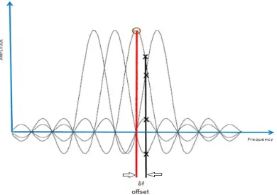
i) Frequency phase shift between the receiver and transmitter: The signal after modulation is centered on a frequency δf instead of being centered at (0MHz), as a result of the phase difference between the frequency of the receiver and transmitter. The CFO is shown in Figure 1,
δf=|FCRX - FCTX |, where FCRX is the carrier frequency of the receiver, and FCTXis the carrier frequency of the transmitter. Baseband transmission transmits the signal as it is without frequency shifting (without modulation). The passband transmission shifts the transmitted signal to a higher frequency and transmits it. In the receiver, the received signal is shifted back to the main frequency.
ii) Doppler effect: The carrier frequency at the receiver (FCRX) can differ due to the Doppler
Effect in the status of mobile receivers. Doppler Effect is the additional source of CFO.
[image:3.612.315.528.68.304.2]iii) Sampling frequency difference: Another source of the CFO is the gap between the sampling frequencies between the destination and the data source.
Figure 1: Effect of CFO
[image:3.612.322.517.452.589.2]The subcarriers are sampled at the peaks. The peaks can happen only when no frequency offset is observed. Nevertheless, if a frequency offset occurs, then the sampling is done at the offset point, which is not the peak point. As such, the amplitude of the anticipated subcarriers is reduced, possibly increasing the ICI from the neighboring subcarriers. Figure 2 illustrates theThe effect of the CFO.
Figure 2: Frequency offset
870
-
a- -b--c- -d-
[image:4.612.109.529.74.679.2]-e-
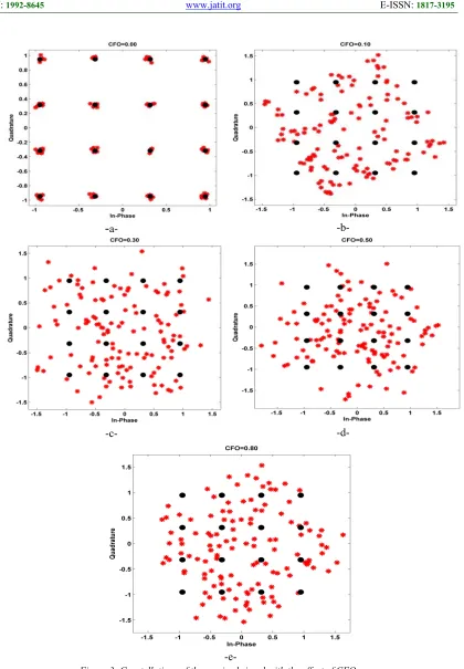
Figure 3: Constellations of the received signal with the effect of CFO
(a) CFO=0.00 (b) CFO=0.10 (c) CFO=0.30 (d) CFO=0.50 (e) CFO=0.80
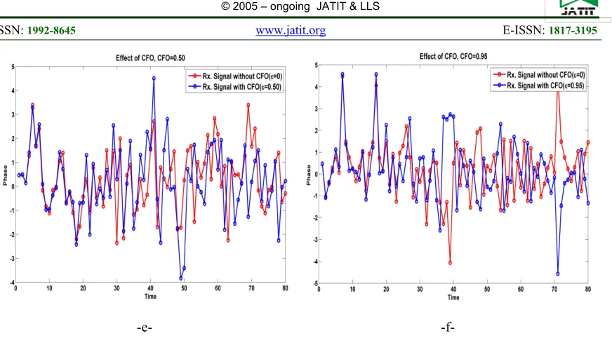
In the TD, the CFO affects the signal illustrated as
871 the CFO (ε = 0). The blue line represents the received signal affected by the CFO (ε ≠ 0). Figure 4 shows that the received signal has been affected by the effect of the CFO and this effect increases
with increasing the value of the CFO. When CFO is increased, the phase difference is increased linearly.
-a- -b-
872
[image:6.612.95.531.57.298.2]-e- -f-
Figure 4: CFO effect (ε) on the signal in time domain (a) CFO = 0.05 (b) CFO = 0.10 (c) CFO = 0.15 (d) CFO = 0.25 (e) CFO = 0.50 and (f) CFO = 0.95
4. CFO ESTIMATION
Whatever the source is, the performance is lost when a frequency offset occurs due to the effect of CFO [22]. The estimation of the CFO may be done in two domains, that is TD or FD.
4.1 Estimation in Time Domain
For CFO estimation in the TD, comprehensive CP and the TS estimation techniques are available.
4.1.1 CFO Estimation Using Cyclic Prefix
A CFO in the received signal that is denoted by ε typically leads to a phase rotation of 2𝝅nε/N with typical symbol synchronization. The phase difference between the conforming part of an OFDM symbol and the CP part (spaced by N samples apart) produced by CFO is expressed as 2𝝅Nε/N = 2𝝅ε. The CFO can be estimated from the product of the corresponding real part of an OFDM symbol and the CP,
𝜀̂ 1
2𝜋arg 𝑦𝑙∗ 𝑛 . 𝑦𝑙 𝑛 𝑁 1
where 𝜀̂ is CFO; n=-1, -2, .., NCP;NCP is the number of samples within CP; yl is the received signal.
The estimated range of CFO in this technique is |ε| < 0.5.
The error function can be expressed as
𝐸 𝑒 𝜎
𝑁 sin 2𝜋𝜀
𝑁 |𝐻 | 𝐾 2
where E is the expectation of error function, eε is the estimation error, 𝜎 is the
transmitted power signal, ε is the normalized CFO, k is a term that comprises transmit and channel powers, L is the number of samples used for averaging, and Hk is the channel frequency of kth subcarrier, K is an expression that includes the channel and transmits power.
4.1.2 CFO Estimation Using Training
Symbol
873 the distance between two blocks of samples used for correlation. This condition becomes possible by using repetitive training symbols with a few small periods. The ratio of the OFDM symbol length to the repetitive pattern is given by R. In the TD, a transmitter sends the training symbols by R repetitive patterns, which are produced by taking the IFFT of the signal in the FD [23],
𝜀̂ 𝑅
2𝜋 𝑎𝑟𝑔 𝑦𝑙 ∗ 𝑛 𝑦𝑙 𝑛
𝑁
𝑅 3
As such, the estimation range is covered by |ε| ≤ 0.5.
4.2 CFO Estimation Techniques in Frequency Domain
The CFO signals of ε are related to one another when the same training symbols are successively transmitted. The synchronization process is generally divided into two phases, namely, tracking and acquisition. In the acquisition phase, a coarse estimate of the frequency offset is obtained and corrected. Therefore, the remaining small deviations are corrected in the tracking phase [23].
One of the technique used is the Moose method,
𝜀̂ 1
2𝜋 tan 𝐼𝑚 𝑌
∗ 𝐾 𝑌 𝑘
/ 𝑅𝑒 𝑌∗ 𝐾 𝑌 𝑘 4
where Im is the imaginary part of the CFO estimation, and Re is the real part.
Another approach is the Classen method,
ε . max .
Y p j , ε . Y∗ p j , ε X∗
p j X p j
5
where L is a number of pilot tones, p[j] is the location of the jth pilot tone, Xl[p[j]] is the pilottone located at p[j], yl and yl+R are two OFDM symbols saved in the memory, and Tsym is the period of symbol.
Therefore, these two methods are used for comparing with the proposed method.
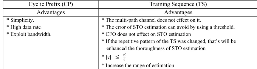
[image:7.612.87.518.490.606.2]Table 1 illustrates the advantages of each method;
Table 1: Advantages & Disadvantages OF CP and TS
Cyclic Prefix (CP) Training Sequence (TS)
Advantages Advantages
* Simplicity. * High data rate * Exploit bandwidth.
* The multi-path channel does not effect on it.
* The error of STO estimation can avoid by using a threshold. * CFO does not effect on STO estimation
* If the repetitive pattern of the TS was changed, that’s will be enhanced the thoroughness of STO estimation
* |ε|
* Increase the range of estimation
5. PROPOSED METHOD
In the TD, the proposed method handles the implementation of CFO by combining with CP and TS methods. The proposed method considers the benefits of TS and CP methods.
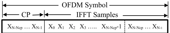
Each symbol that goes out from the transmitter has an IFFT sequence sample that contains N+Ncp;
𝑇
𝑥 𝑛 𝑁 𝑁 𝑛 0
874 where TX(n) is the transmitted IFFT samples after adding CP and N is the number of FFT symbols as shown in Figure 5.
[image:8.612.181.459.158.212.2]OFDM Symbol
CP IFFT Samples
Figure 5: Structure of the OFDM symbol with cyclic prefix
The experimental results prove that the length of CP should be equal to the ¼ symbol for each transmission symbol (¼ of the FFT size) to provide the minimum difference between true and estimated samples. Any increase or decrease in the
[image:8.612.122.493.322.433.2]length of the CP period can affect the receiving symbols. Table 2 illustrates the increase or decrease of the size of CP with the effects on the estimated samples.
Table 2. Differences between true and estimated samples
In any way, the length of CP must be equal to or greater than the delay of the multipath channel (to keep the subcarriers orthogonality and to prevent the overlap between the symbols). Any increase or decrease of the value of a CP leads to a decrease in the throughput or loss it.
All the simulations in this research are based on the values in Table 3,
Table 3: Parameters used in simulation Parameter The value
N (points FFT size) 64
NCP 16 (N/4)
Modulation type 16QAM
NOFDM N+NCP
No. of Symbols (as in simulation)
5
No. of Samples in each Symbol 80
No. of Samples 400
SNR range 0 ~ 30 (step 3)
Channel AWGN
Figure 6 shows the algorithm for finding CFO by using CP ("CFO_by_CP”)
Algorithm CFO, CFO_by_CP algorithm 1:
2: 3: 4: 5: 6: 7: 8: 9: 10:
procedure CFO_by_cyclic prefix (Rx, Nfft, Ncp)
for n=1 Ncp do
TM 1/2π B1 Rx(n+Nfft) B2 conjugate Rx(n) CFO phase angle (B1 * B2) CFO CFO * TM
end for return CFO
end procedure
Figure 6: CFO Algorithm by cyclic prefix
Figure 7 shows the algorithm of finding a mean square error (MSE) by using “MSE_by_CP” algorithm.
Size of CP Position of true and estimated samples
CP = ¼ FFT size
True at samples: 81 161 241 321 401 Estimated at samples: 80 161 238 321 401 Differences: -1 0 -3 0 0
CP = ½ FFT size True at samples: 97 193 289 385 481 Estimated at samples: 82 177 272 367 463 Differences: -15 -16 -17 -18 -18
CP = ⅛ FFT size True at samples: 73 145 217 389 461 Estimated at samples: 69 141 214 386 355 Differences: -4 -4 -3 -3 -6
[image:8.612.312.528.488.629.2]875
Algorithm MSE, MSE_by_CP algorithm 1: 2: 3: 4: 5: 6: 7: 8: 9: 10: 11: 12: 13: 14: 15: 16:
procedure MSE_by_cyclic prefix
for i=1 length (SNR) do
sum_CP 0
call CFO_by_CP algorithm
find the sum of the difference between estimated values and actual values
B_CP temp2
for j=1 length (B_CP) do
sum_CP sum_CP + B_CP end for
MSE_CP(i) sum_CP / length (B_CP)
end for
return MSE_CP
[image:9.612.92.425.70.289.2]end procedure
Figure 7: MSE Algorithm with cyclic prefix
In the receiver, the CFO estimation can be done using transmitted TS. Figure 8 shows the "CFO_by_TS” algorithm which is used in CFO estimation in the proposed method
Algorithm CFO, CFO_by_TS algorithm 1: 2: 3: 4: 5: 6: 7: 8: 9: 10:
procedure CFO_by_training (Rx, Nfft, R)
for n=1 (Nfft/R)-1 do
TM R/2π A1 Rx(n+Nfft/r) A2 conjugate Rx(n) CFO phase angle (A1 * A2) CFO CFO * TM
end for return CFO
end procedure
Figure 8 CFO Algorithm by training sequence
Figure 9 shows the MSE algorithm using TS which is called “MSE_by_TS”
Algorithm MSE, MSE_by_TS algorithm 1: 2: 3: 4: 5: 6: 7: 8: 9: 10: 11: 12:
procedure MSE_by_training
for i=1 length (SNR) do
sum_TS 0
call STO_by_TS algorithm
find the sum of the difference between estimated values and actual values
A_TS temp2
for j=1 length (A_TS) do
sum_TS sum_TS + A_TS end for
MSE_TS(i) sum_TS / length 13: 14: 15: 16: (A_TS) end for
return MSE_TS
end procedure
Figure 9: MSE Algorithm with training sequence
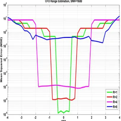
[image:9.612.317.521.288.491.2]As shown in Figure 8, R is the repetitive patterns of the TS that the transmitter sends in the TD. It is an integer number. When R increases, the CFO estimation range becomes wide further by (|ε| ≤ R/2) thereby decreasing the number of samples. In addition, the performance of the MSE becomes worse. However, the CFO estimation range (tracking range) increases as illustrated in Figure 10.
Figure 10: CFO range estimation vs. MSE performance
[image:9.612.86.301.384.511.2] [image:9.612.86.303.579.738.2]876 SNR.
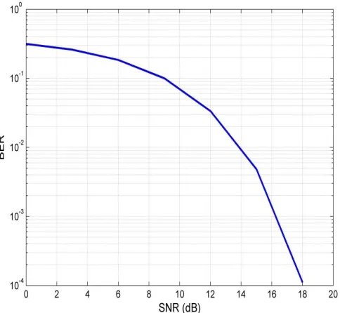
The two factors (SNR and BER) are used as communication protocols. Hence, in this research, the SNR is the indicator used to change the estimation method from TS to CP. Relative to the value of 18 dB, SNR is the converging point that occurs to get the continuity of the estimation
[image:10.612.183.425.217.440.2]in the receiver. Figure 11 shows that the BER decreases when the SNR increases. At the end of the curve, the BER is nearly equal to zero when SNR is equal to 18 dB. Therefore, as long as BER is equal to zero, the value of the SNR is equal to18 dB. This value of SNR is used for changing from one method to another.
Figure 11: SNR with respect to BER
In the receiver, by merging the previous algorithms (“CFO_by_CP” and “CFO_by_TS”), a new algorithm is obtained as shown in Figure 12.
New results related to the CFO in the received data are calculated.
Algorithm Merge, Merge_CP_TS algorithm 1:
2: 3: 4: 5: 6: 7: 8: 9: 10: 11: 12: 13: 14: 15: 16:
procedure Merge_CP_TS iter number of iterations
for i=1 length (SNR) do
MSE_CFO_CP 0 MSE_CFO_TS 0 call Add_CFO algorithm calculate error
for j=1 iter do
if error < 0.0001
call CFO_by_CP algorithm
MSE_CFO_CP_ST MSE_CFO_CP else
call CFO_by_TS algorithm
MSE_CFO_CP_ST MSE_CFO_TS
end if
877 17:
18: 19:
Merge (i) MSE_CFO_CP_ST / iter
return Merge
end procedure
Figure 12: Merge Between Cyclic Prefix And Training Sequence
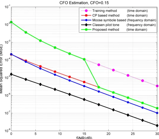
Figure 13 shows the switching from the TS approach to the CP approach as long as SNR ≥ 18 dB. This swithching improves the performance of OFDM synchronization. Therefore, the proposed
method has simplicity, high data rate, and increased range of estimation.
Figure 13: Changing from TS part to CP part
6. CONCLUSION
In this research, the study of CFO effect was done in the TD used by the OFDM system. A novel method is proposed for CFO estimation through the hybrid of the TS method with the CP method so that the advantages of both methods are employed. The proposed method is achieved by developing a new method to estimate the beginning of the received OFDM symbol by using two combinations techniques, TS and CP techniques, rather than using previous techniques. It is based on the CP size which equals to the quarter of the FFT size. It depends on the value of SNR with respect to BER to change from one method to another one with the best value of the SNR is 18 dB. This value was improved practically with Figure 11. The estimation of the proposed method is better that that of previous methods. The effect
of CFO was applied to the proposed and previous method with different values of them.
REFERENCES
[1] M. Benzarti, M. Messaoudi, and S. Hasnaoui, “Wimax timing and frequency synchronization based on training sequence”, IEEE Web Applications and Networking (WSWAN), 2015, pp 1-7.
[2] A. Agarwal1 and K. Agarwal, “Implementation and Performance Evaluation of OFDM System in Diverse Transmission Channel Using Simulink”, American Journal of Electrical and Electronic Engineering, Vol. 3, No. 5, 2015, pp. 117-123.
[image:11.612.174.442.225.459.2]878 [4] R. Thakur and K. Khare, “Synchronization
Techniques in OFDM Systems”, International Journal of Computer Networks and Wireless Communications, Vol.2, No. 6, 2012, pp. 693-696.
[5] F. Xiong, “Digital Modulation Techniques”, Second Edition, Artech House, Boston, London, 2006, pp. 745-797.
[6] W. Aziz, E. Ahmed, G. Abbas, S. Saleem, and Q. Islam, “Performance Analysis of carrier Frequency Offset (CFO) in OFDM using MATLAB”, Journal of Engineering (JOE), Vol. 1, No. 1, 2012, pp. 5-10.
[7] Y. S. Cho, J. Kim , W. Y. Yang, and C. G. Kang , “MIMO-OFDM wireless communications with MATLAB”, John Wiley & Sons, Asia, IEEE Press, 2010, pp. 153-161 [8] J. Lee, H. Lou, D. Toumpakaris, and J. M.
Cioffi, “Effect of Carrier Frequency Offset on OFDM Systems for Multipath Fading Channels”, Global Telecommunications Conference In IEEE, 2004, Vol. 6, pp. 3721- 3725
[9] T. Pollet, M. Van Bladel, and M. Moeneclaey, “BER sensitivity of OFDM systems to carrier frequency offsetand wiener phase noise,” IEEE Transaction on Communications., 1995, Vol. 43, No. 2/3/4, pp. 191–193.
[10] G. Abshir, M. M. Abdullahi, and M. A. Samad, “A comparative study of carrier frequency offset (CFO) estimation techniques for OFDM systems”, IOSR Journal of Electronics and Communication Engineering, 2014, Vol. 9, No. 4, pp. 1-6.
[11] P. H. Moose, “A technique for orthogonal frequency division multiplexing frequency offset correction,” IEEE Transactions on Communications, 1994, Vol. 42, No. 10, pp. 2908 – 2914.
[12]F. Classen, and H. Myer, “Frequency synchronization algorithm for OFDM systems suitable for communication over frequency selective fading channels”, Proceedings of IEEE Vehicu;ar Technology Conference (VTC), 1994, pp. 1655-1659.
[13]T. M. Schmidl, and D. C. Cox, “Robust frequency and timing synchronization for OFDM,” IEEE Transactions on Communications, 1997, Vol. 45, No. 12, pp. 1613 – 1621.
[14]M. M. U. Gul, X. Ma, and S. Lee, "Timing and frequency synchronization for OFDM downlink transmissions using Zadoff-Chu sequences" IEEE Transactions on Wireless
Communications. 2015, Vo. 14, No. 3, pp. 1716-1729.
[15]T. Yang, and L. Hu, “An improved frequency offset estimation algorithm for OFDM system”, IEE International Conference on Information Networking and Automation (ICINA), 2010, Vol. 1, pp. V1-10.
[16]A. Pelinkovic, S. Djukanovic, I. Djurovic, and M. Simeunovic, “A frequency domain method for the carrier frequency offset estimation in OFDM systems”, IEEE International Symposium In Image and Signal Processing and Analysis (ISPA), 2013, pp. 326-330. [17]A. Eslahi, A. Mahmoudi, and H. Kaabi,
“Carrier Frequency Offset Estimation in OFDM Systems as a Quadratic Eigenvalue Problem”, RADIO ENGINEERING, 2017, Vol. 26, No.4, pp. 1138-1142.
[18]Y. Chunlin, L. Shaoqian, T. Youxi, L. Xiao, F. Jiayi, “A Novel Frequency Offset Estimation Methodfor OFDM Systems with Large Estimation Range,” IEEE Transactions on Broadcasting, 2006, Vol. 52, No. 1, pp. 58 – 61.
[19]Y. Tiejun, H. Lei, “An improved frequency offset estimation algorithm for OFDM system”, IEEE International Conference on Information, Networking and Automation(ICINA), 2010, pp. 10 – V1-13.
[20]G. M. Hassan, K. A. A. Azmi, and M. R. Mokhtar, “Sending Image in Noisy Channel Using Orthogonal Frequency Division Multiplexing Scheme”, Journal of Theoretical & Applied Information Technology (JATIT), 2018, Vol. 96, No.12, pp. 3719-3801.
[21]D. Kayalvizhi, N.Nagavalli, and J.Arivazhagan, “Carrier Frequency Offset Estimation in MIMO OFDM Systems”, International Journal of Emerging Technology in Computer Science & Electronics (IJETCSE), 2015, Vol. 13, No. 2, pp. 332-335. [22]K. Sandeep, S. Charanjit, S. S. Amandeep,” Effects and Estimation Techniques of Symbol Time Offset and Carrier Frequency Offset in OFDM System: Simulation and Analysis”, International Journal of Electronics and Computer Science Engineering, 2012, pp. 1188-1196.