http://dx.doi.org/10.4236/jcc.2015.36008
Non-Vanishing Space Time Block Code for
Three Time Slots and Two Transmit
Antennas
Ali Azarbar
Department of Electrical and Computer Engineering, Islamic Azad University, Parand Branch, Tehran, Iran Email: [email protected]
Received 30 March 2015; accepted 30 May 2015; published 3 June 2015
Copyright © 2015 by author and Scientific Research Publishing Inc.
This work is licensed under the Creative Commons Attribution International License (CC BY).
http://creativecommons.org/licenses/by/4.0/
Abstract
Recently, space time block codes (STBCs) are proposed for multi-input and multi-output (MIMO) antenna systems. Designing an STBC with both low decoding complexity and non-vanishing prop-erty for the Long Term Evolution Advanced (LTE-A) remains an open issue. In this paper, first our previously proposed STBC’s non-vanishing property will be completely described. The proposed STBC scheme has some interesting properties: 1) the scheme can achieve full rate and full diversi-ty; 2) its maximum likelihood (ML) decoding requires a joint detection of three real symbols; 3) the minimum determinant values (MDVs) do not vanish by increasing signal constellation sizes; 4)
compatible with the single antenna transmission mode. The sentence has been dropped. Second, in order to improve BER performance, we propose a variant of proposed STBC. This scheme further decreases the detection complexity with a rate reduction of 33%; moreover, non-vanishing MDVs property is preserved. The simulation results show the second proposed STBC has better BER performance compared with other schemes.
Keywords
Space Time Block Codes, Maximum Likelihood Decoding, Non-Vanishing Minimum Determinant Value
1. Introduction
en-counter independent fading. Thus, transmit (receive) antennas must be separated appropriately. Therefore, if each replica of transmitted signals encounters independent fading, the probability of occurring deep fading is very unlikely. Alamouti code is the most popular STBC scheme for two-transmit antennas systems [1]. It achieves code rate one and full diversity transmission using two-time slots for information symbols. Tarokh and et al. generalized Alamouti code for systems with an arbitrary number of transmit antennas which are called or-thogonal codes [2]. Although, these codes provide full diversity for more than two transmit antennas with linear decoding complexity code rate is less than one. To increase code rate for more than two transmit antennas, Qua-si-Orthogonal STBC (QSTBC) scheme is introduced in [3] and [4]. However, code rate is increased for QSTBC scheme decoding complexity is higher, but not exponentially, compared with orthogonal codes.
The Three Generation Partnership Project (3GPP) started the next generation wireless systems (4G) under the project Long Term Evolution Advanced (LTE-A) in 2008 [5]. In LTE-A, user equipment (UE) is imposed two transmit antennas. Therefore, STBC scheme can be the most popular candidate for the uplink diversity gain [6]. Alamouti STBC scheme sounds a suitable candidate in LTE-A systems. Unfortunately, in LTE frame structure is dedicated 3-time slots with Alamouti STBC scheme. This has brought up an interesting STBC design problem which is compatible with LTE frame structure. Hybrid STBC scheme as the first scheme has been proposed for 3-time slots and two transmit antennas systems [7]. Its encoding matrix includes two time slots Alamouti scheme followed by one time slot repetition transmission. Although, the Hybrid scheme achieves code rate one and its decoding complexity is linear at receiver does not achieve full diversity. To remove full diversity defect, a class of QSTBC scheme is proposed by Lie et al. in [8] [9]. The QSTBC scheme achieves code rate one and full diversity. But, there are two problems with this scheme. The first problem is highcomplexity of maximum likelihood (ML) decoding which requires a joint detection of two complex symbols (O(M2)), where M is size of the used symbol constellation. The second problem is that the minimum determinant values (MDVs) extremely vanish by increasing the symbol constellation size. Recently, Fast-Group-Decodable STBC (Fast-GSTBC) scheme has been proposed in [10] [11]. As generic construction method for odd-time slot, new GSTBC scheme has been designed for LTE-A that achieves code rate one and full diversity with symbol-wise decoding com-plexity (O(M1)) [12]. GSTBC scheme achieves code rate one and full diversity with symbol-wise decoding complexity (O(M1)). However, GSTBC scheme reduces decoding complexity for 3-time slots two transmit an-tennas its MVDs vanish. Also, this scheme is not compatible with single antenna.
In [13], a novel 3-time slots STBC structure, based on trace criterion, has been designed. To the best our knowledge, this is the first 3-time slots two transmit antennas STBC scheme which has non-vanishing MDVs property. In this paper, by using this STBC structure, 1) a 3-time slots STBC scheme which can achieve code rate one and full diversity with decoding complexity of O(M1.5) is proposed, 2) a 3-time slots code rate 2/3 STBC scheme which can achieve full diversity with symbol-wise decoding complexity is obtained. Also, we will show that both schemes have non-vanishing MDVs property. The simulation results show that our first scheme has the same bit error rate (BER) performance with the GSTBC scheme. However, BER for the second proposed scheme is improved about 0.3 dB compared with the first scheme.
The rest of the paper is organized as follows: Section 2 comprises two subsections: 2.1. Channel Model, 2.2. Code Design Criteria, and 2.3. Review of Three Time Slots Two Transmit Antennas STBC Schemes. In Section 3, the Non-Vanishing MDVs Code Rate One 3-Time Slots STBC is introduced. This section includes four subsec-tions: 3.1. Encoding matrix, 3.2. Parameter k Optimization, 3.3. Decoding Complexity, and 3.4. Some X1pro Properties. In Section 4, Code Rate 2/3 3-time slot 2-antenna STBC is introduced. In Section 5, Simulation Re-sults and Discussion is presented: 5.1. Performance Comparison in Rate One Scheme,and 5.2. Performance Comparison in Rate 2/3 Scheme. Conclusion is given in Section 6.
Notations: Hereafter,
j
= −
1
, small letters, bold letters and bold capital letters will designate scalars, vec-tors, and matrices, respectively. If A is a matrix AH, AT, and tr(A) denote the conjugate-transpose, transpose, and trace of A, respectively;( )
. R,( )
. I and( )
. ∗ denote the real part, the imaginary part and the complex conju-gate, respectively.2. Review of 3-Time Slots STBC for Two Transmit Antennas
2.1. Cannel Model
re-ceiver but unknown at the transmitter. The input-output relation of this system can be written as
q
=
+
Y
XH
Z
(1) where the normalization q(
q
=
ρ
N
t)
is to ensure that the ρ (SNR at the receiver) is independent of the number of the transmit antennas (Nt). X is the T×Nt complex matrix of the transmitted symbols that are drawn constellation. H is the Nt×Nr complex matrix that contains all the channel coefficients with zero mean and unit variance. Z is the T×Nr complex noise matrix, and Y is the T×Nr complex matrix of the received signals. The entries of Z are assumed to be i.i.d. complex Gaussian random variables with the probability density function (pdf)CN
(
0,
N
0)
, whereCN
( )
.,.
stands for the complex Gaussian pdf and N0 for the noise va-riance.2.2. Code Design Criteria
2.2.1. Rank and Determinant Criteria
Recently STBC schemes mainly rely on analysis of the pair wise error probability (PEP) P
(
X →Xˆ)
which is the probability thatX
ˆ
is detected while X is transmitted. Chernoff bound Analysis of the PEP at high SNR values results in Rank criterion and Determinant criterion [14]. The STBC scheme has full diversity property if the difference matrix(
X →Xˆ)
is full rank for all codeword pairs. The diversity gain at high SNR values do- minates the steepness of the Bit Error Rate (BER) curve. Thus, in STBC scheme design ensuring full diversity is important at high SNR values. Afterwards, coding gain should be maximized for given average transmit power that leads to a good determinant criterion. The maximum coding gain results in the minimum PEP. Besides maximizing coding gain, this value should be constant for any symbol constellation sizes. This property is called non-vanishing MDV and has been established for several popular STBC schemes [15]-[18]. The non-vanishing MDV can beexploited through the use of the adaptive constellation (adaptive rate) according to the wireless channel quality.2.2.2. Trace Criterion
The trace criterion is less known but paramount for designing non-orthogonal STBC schemes [19] [20]. This criterion states: to optimize performance of the BER STBC scheme, say X , should be designed so that the ei- genvalues of the
(
X−Xˆ) (
H X−Xˆ)
are as close as possible to each other and to tr(
(
X−Xˆ) (
H X−Xˆ)
)
T, and for which the row-wise sum of the absolute values of the elements off the main diagonal is as small as possible. Moreover, the tr(
(
X−Xˆ) (
H X−Xˆ)
)
plays the role of the Euclidean distance between codewords.2.3. Review of Three Time Slots Two Transmit Antennas STBC Schemes
In this section, the three time slots two transmit antennas STBC schemes has been reviewed. Also, advantageous and disadvantageous of the all schemes are included.
2.3.1. Hybrid STBC Scheme
The hybrid scheme, XHSTBC, is the first 3-time slot STBC scheme has been proposed [7]. Encoding matrix of this scheme is prescribed in (2). As can be seen in encoding matrix, Alamouti STBC is used at fist 2-time slots, and symbol s3 is repeated at the last time slot over both antennas. Such STBC scheme has code rate one with linear decoding at receiver and symbols are encoded by standard modulation that has low hardware complexity. Because symbol s3 is not transmitted in different time slot, full diversity does not achieve.
T *
1 2 3
*
2 1 3
HSTBC
s s s s s s
−
=
X (2)
2.3.2. QSTBC Scheme
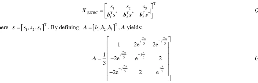
Incapacitation of Hybrid STBC to achieve full diversity was good reason for author in [8] [9] to design a class of QSTBC scheme,
X
QSTBC, compatible with 3-time slots systems. The encoding matrix of such scheme has a general form ofT
1 2 3
T * T * T *
1 2 2
QSTBC
s s s
=
X
b s b s b s (3) where s=
[
s s s1, 2, 3]
T. By defining A=[
b b b1, 2, 3]
T, A yields:2π 2π
5 5
2π π
5 5
2π π
5 5
1 2e 2e
1
2e e 2
3
2e 2 e
j j
j j
j j
−
−
−
= −
−
A (4)
QSTBC
X
has code rate one, full diversity, and backward compatible with single antenna properties. Also, it is proven that ML decoding complexity of theX
QSTBC is O(M2). There is two defects withX
QSTBC. First defect is high decoding complexity, and second MDVs vanish by increasing symbol modulation orders (i.e. non-va- nishing MDV property does not preserve). Also, the rotation factors in matrix A may cause encoder and de-coder accommodate three different constellations our simulations show for 4-QAM modulation. MDV is 7.18 while for 16-QAM this value is 0.12. Therefore in order to reduce the decoding complexity, the code in subsec-tion II.C.3. is proposed.2.3.3. Group-Decodable STBC Scheme
Recently Fast-Group-Decodable STBC (Fast-GSTBC) scheme has been proposed in [10] [11]. As generic con-struction method for odd-time slot, new GSTBC scheme with arbitrary code dimension including odd time slot has been designed. Based on Fast-Group-Decodable STBC, in [12] a new STBC scheme for LTE-A system was designed as follows
T *
1 2 1 2
3
* *
1 2 1 2
3
2 2
2 2
GSTBC
s s s s
s
s s s s
s
+ − +
−
=
+ − +
X (5)
GSTBC
X achieves code rate one and full diversity with symbol-wise decoding complexity. Encoder/decoder only needs to accommodate one rotated constellation that reduces hardware complexity. However, similar to scheme in (4) XGSTBC cannot preserve non-vanishing MDVs property. For 4-QAM and 16-QAM, MDV is 16, but for 8-QAM the MVD is 6.18. Also, this scheme is not suitable for single antenna transmission.
So, design of 3-time slots two-transmit antennas STBC scheme with non-vanishing MDVs is required. In the next section a novel STBC structure with non-vanishing MDVs property that has been proposed in [13] will be presented.
3. Non-Vanishing MDVs Code Rate One 3-Time Slots STBC
In this section, initially the encoding matrix is presented. Then, parameter k is optimized to maximize the MDVs. Also, we will prove that our scheme achieves non-vanishing MDVs. Finally, the decoding complexity of the proposed STBC scheme with ML criterion is illustrated.
3.1. Encoding Matrix
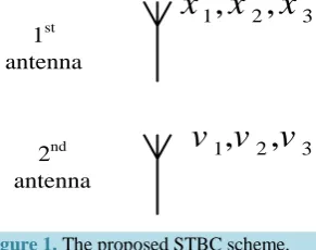
[image:4.595.97.532.135.276.2]In this subsection, the problem is formulated.
Figure 1. The proposed STBC scheme.
transmitted symbols during time slots). The 1st antenna transmits the three symbols x1, x2,and x3 during three time slots. The 2nd antenna transmits three symbols v1, v2, and v3. Now, the three symbols transmitted by the 2nd antenna will be defined. One possible way to define these symbols is to make vector v (v = [v1v2v3]) orthogonal to vector s (s = [x1 x2 x3]), i.e. s vH =v sH =0. As will be shown in the next subsection this causes the decoding complexity reduces from joint three complex symbols detection to joint three real symbols; moreover results in suitable trace criteria [19] [20]. Then, improve BER performance at high SNR. To achieve this goal, three dif-ferent STBC schemes are proposed as:
T T
T
1 2 3 1 2 3
1 2 3
1 * * 2 * * 3 * *
3 1 3 2
2 1
, ,
0 0
0
x x x x x x
x x x
x x x x
x x
= = =
− −
−
X X X (6)
In all of the above schemes, the first row is orthogonal to the second one. However, zero entry in the second row reduces diversity order. The following solution overcomes to this deficiency:
1 2 3
,
=
X+
X+
Xv
v
v
v
(7)where i
X
v
(i = 1, 2, 3) is the second row in matrix Xi. Therefore, v yields as * * * * * *2 3, 1 3, 1 3
x x x x x x
= − − − +
v .
In order to achieve power balance, the symbols in the vector v are transmitted with power
1
2
. Now, we can present the proposed encoding matrix as:T
1 2 3
1 * * * * * *
2 3 1 3 1 2
2 2 2
pro
x x x x x x x x x
= − − − +
X (8)
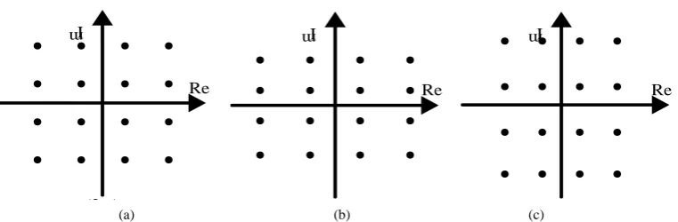
For full diversity, symbols x1, x2, and x3 are selected from three different symbol constellations.Figure 2 represents these three symbol constellations. From the represented constellations xi (i = 1, 2, 3) are obtained as
[21]:
(
)(
)
(
)(
)
1
2 2
2 3
,
2 1 ,
2 1 .
R I
R I
R I
x s js
x k s jks x k ks js
= +
= + +
= + +
(9)
Power 2 1
(
+k2)
in2
x and x3 guarantees εxi2 = 1 (i = 1, 2, 3), where
ε
[ ]
z
is the excepted val- ue of z. sR and sI are chosen from the standard QAM constellation. Parameter k is unknown and must be optimized to maximize the MDVs. In the subsection III.B the parameter k will be optimized. Note that despite the first row is orthogonal to the second one X1pro is neither orthogonal code nor quasi-orthogonal. Consider orthogonal code, say Xorth, thenX
orthHX
orth=
α
I
, in which 21
K k k s
α=
∑
= and I is identity matrix.3.2. Parameter K Optimization
In the previous subsection, the three different symbol constellations were represented. The parameter k norma- 1
,
2,
3x
x
x
1
,
2,
3v v v
1st antenna
(a) (b) (c)
Figure 2. Three different symbol constellations. (a) The standard QAM constellation that symbol x1 is chosen from; (b) The horizontally stretched QAM constellation that symbol x2 is chosen from; (c) The vertically stretched QAM constellation that symbol x3 is chosen from.
lizes symbols x2 and x3. In this subsection the parameter k is optimized.
(
)
02 2H H
H
H H
det det ×
= ≠
s s v s X X
s v v v
(10)
Where X =X1pro−Xˆ1pro and
1 ˆ1
and
pro pro
X X represent two different codewords and det(.) denotes determinant value of (.).
According to v sH =s vH =0, it is easy to show that X is full rank. Note that when k=1, it is possible 0
=
v , although we consider 0< <k 1 in 3.1. This vouches that determinant is always nonzero. Then,
(
)
3 3(
)
2 2 * * *
2 3 1 3 1 2
1 1
min H i i R
i i
det x x x x x x x x
= =
= + − +
∑
∑
X X (11)
where xi =xi−xˆi (i = 1,2,3), and xi represents the possible error in symbol xi. Lemma 1: X1pro has non-vanishing-MDV and for dmin =1 its value is 5.82. Prove:
Consider M-ary QAM standard constellation, where the real and image components of a symbol can be viewed as M1-ary standard PAM and M2-ary standard PAM symbols, respectively (e.g. 8-ary QAM constellation can be considered as 4-ary PAM and 2-ary PAM for real and image components, respectively). Then, for real components,
x
1R=
2
m d
1 min,(
2)
2 2 2 2 1 min
R
x = m +k d , and 2
(
2)
3 2 3 2 1 min
R
x = m k +k d , dmin is the mini- mum Euclidian distance between the PAM constellation points and here is considered as 1. mi (i = 1, 2, 3) is an integer such that mi∈
{
[
M1−1: 2 :−M1+1]
0}
.With the above assumptions, the optimized MDV for 4-QAM (for traceability constellation is assumed 4- QAM) in (11) is achieved for
m
i∈
{
0, 1
±
}
, observe thatm
i∈
{
0, 1
±
}
is compatible with any QAM constella-tion size. As menconstella-tioned before, when 0< <k 1, the determinant in (11) is nonzero. To optimize MDV and show non-vanishing-MDV property, define expression D as follows:(
2 2 2)(
2 2 2)
1 2 3 1 2 3 2 3 1 3 1 2
D= z +z +z z +z +z +z z −z z +z z (12)
where z1=m1,
(
2)
2 2 2 1
z =m +k , and 2
(
2)
3 3 2 1
z =m k +k . In fact, D is similar the expression in (11) that normalized by
16
d
min4 and for traceabilityx
1I=
x
2I=
x
3I=
0
is considered. Since the first term in (12) isalways nonzero define
(
2 2 2)
1 2 3 2 3 1 3 1 2
D′ = z +z +z +z z −z z +z z <D. Now, suppose two following cases: case1: z1=0, this case yields:
(
2)
2 1
2
2 3 3
D′ = z +z +z z (13) According to z2 and z3 and k, the minimum value is always obtained for z2=0 and z3≠0. Then, we define
D
1,min′
as follows⦁ ⦁ ⦁ ⦁
⦁ ⦁ ⦁ ⦁
⦁ ⦁
⦁ ⦁
⦁ ⦁ ⦁ ⦁
Re
I m
(2.a)
⦁ ⦁ ⦁ ⦁
⦁ ⦁ ⦁ ⦁
⦁ ⦁
⦁ ⦁
⦁ ⦁ ⦁ ⦁
Re
I m
(2.b)
Re
I m
⦁ ⦁ ⦁ ⦁
⦁ ⦁ ⦁ ⦁
⦁ ⦁
⦁ ⦁
⦁ ⦁ ⦁ ⦁
[image:6.595.124.505.84.209.2]
( )
2(
2(
2)
)
1,min 3 2 1
D′ k =m k +k (14) Note, both z2 and z3 cannot be zero at the same time.
case 2: z1≠0, this case yields:
(
) (
(
)
)
(
(
)
)
(
(
)
)
(
)
(
)
2 2 2 2 2 2 2
1 2 3 2
2 2 2
2 3
1 2 3
1
2 1 2 1 2 1
2 1 2 1
D m m k m k k m m k k m m k k m m k
′= + + + ′ + + ′ +
′
− + + + (15)
{
}
3 0, 1
m′ ∈ ± , is different from m3 in (13). It is clear for m1= −m2=m3′≠0, D2′ has minimum determinant value. Then, D2,min′ is defined as follows:
( )
(
(
(
2)
)
2(
2)
(
2)
)
23
2,min 3 2 1 2 1 2 1 .
D′ k = − k +k − k +k − +k m′ (16)
In order to maximize MDVs, equate
D
1,min′
( )
k
andD
2,min′
( )
k
:( )
( )
{ }
1,min 2,min 3
,
31 .
D
′
k
=
D
′
k
∀
m m
′
∈ ±
(17) This equality yields k=0.66 and corresponding MDV is mindet=5.82 when dmin =1. therefore, the obtained mindet is the maximum mindet for all k.Note that mi∈
{
0, 1±}
is assumed, this assumption is compatible with any constellation size.3.3. Decoding
To illustrate the decoding complexity of the proposed STBC scheme with the ML criterion, the decision metric used for the ML decoder will be derived.
Consider a single antenna at receiver Nr =1, the ML decoder metric is:
2
,
−
y Xh (18) where X, h and y are represented in (1). The objection of the
ML decoder is to obtain optimal X between all of the possibilities which minimize (12). After some manipu-lations,
(
) (
)
2
1, 2, 3 1, 2, 3
R R R I I I
R I
f x x x f x x x
− = +
y Xh (19)
where
(
)
{ }
{ }
{ }
(
)
(
)
2 2
2 2 2
1 2 3 1 2 3 1 2 3
1 2
2 3 1 3 1 2 2
, , R R R
R R R R R R R R R
R i
i R R R R R R
f x x x a x b x c x x x x h x x x x x x h
= = + + + + + + − +
∑
(20.1) and(
)
{ }
{ }
{ }
(
)
(
)
2 22 2 2
1 2 3 1 2 3 1 2 3
1 2
2 3 1 3 1 2 2
, ,
,
I I I
I I I I I I I I I
I i
i I I I I I I
f x x x a x b x c x x x x h x x x x x x h
= = + + + + + + − +
∑
(20.2) and(
)
(
)
(
)
* * * * * *1 1 2 3 2 2 1 1 3 2 3 1 1 2 2
2 2 , 2 2 , 2 2 .
a= − r h − r −r h b= − r h − r −r h c= − r h − r −r h
as BPSK, the proposed scheme will have highest decoding complexity among the three time slots two transmit antennas schemes.
3.4. Some
X
pro1
Properties
Simple but important properties of the proposed code are illustrated.
• full rate and full diversity
It was mentioned that three information symbol are transmitted from two antennas during three time slots. This achieves full rate property. Also, when 0< <k 1, the determinant of the difference matrix
(
H)
X X is always nonzero. This ensures full diversity property.
• Non-vanishing MDVs
It was proved in lemma 1 X1pro always has nonzero determinant that guarantees 1 pro
X achieves full diver-sity, and its MDVs do not vanish by increasing symbol constellation sizes. Non-vanishing MDVs property dis-tinguishes our scheme from other schemes have been proposed for LTE-A systems.
• Compatible with single transmit antenna
Our scheme has the property that first row is x x x1 2 3 in (8), such property provide backward compatible for single antenna, which is desired in LTE-A. QSTBC encoding matrix in (3) is also compatible with single anten-na system while XGSTBC has not such property.
4. Code Rate 2/3 3-time Slot 2-Antenna STBC
It was shown X1pro has non-vanishing-MDV property, but its decoding complexity slightly is high. To reduce detection complexity another STBC scheme, X2 3pro, is proposed.
2 3 pro
X has these properties: 1) detection com-plexity reduces from order 1.5 to 1; 2) non-vanishing-MDV is preserved in X2 3pro; 3) code rate reduces from 1 to 2/3.
Encoding Matrix
The structure of X2 3pro is same 1 pro
X . However, encoding of symbols is different from X1pro. Consider detec-tion funcdetec-tion in (19) again:
(
) (
) (
)
21, 2, 3 1 , 2, 3 2 3 1 3 1 2 2
R R R R R R R R R R R R
f s s s =g s s s + x x −x x +x x h
At the above expression, the last term is called symbol interference term. We can decrease interference by omitting one of the information symbols, say x3. In fact, instead of three symbols, two symbols, s1, s2, is transmitted. Note, the structure of the encoding matrix is preserved for X2 3pro, but encoding of symbols is changed as follows:
1 1
,
2 2, and
3 1R I
x
=
s
x
=
s
x
=
js
(21) andT
1 2 3
2 3
* * * * * *
2 3 1 3 1 3
pro
x x x
x x x x x x
= − − − +
X (22)
where s1 and s2 are chosen from the M-QAM standard constellation. Following lemma shows this scheme ensures non-vanishing MDVs property, too.
Lemma 2: X2 3pro has non-vanishing-MDV and its value is 32 when dmin=1. The determinant for X2 3pro is obtained:
(
)
(
2 3 2 3)
(
2 2)
(
2 2(
)
)
1 2 1 2 1 2
1 2
2 .
H R
pro pro
det X X ≡D= s + s s + s + s s⋅
(23)
is always greater than zero, we define D′ =
(
s12+ s22+(
s s1⋅ 2)
R)
<D. For traceability( ) ( )
s1 I = s2 I =0. Then, D′ yields:2 2
1 2
1 2
R R R R
D
′
=
s
+
s
+
s s
(24) where si = −si s iˆi, =1,2 and as mentioned before si and sˆi are chosen from M-QAM standard constella-tion. Thus1 1 min
2 2 min
2 2 R
R
s m d
s m d
= =
(25)
where mi (i = 1, 2) is an integer such that mi∈
{
[
M1−1: 2 :−M1+1]
0}
. Replace (24) by (25) and normalizeby
4
d
min2 we obtain,(
2 2)
1 2 1 2 .
D′= m + m +m m (26) Assume following two cases:
Case 1: m1=0 or m2=0
This case results in:
1 2
i
D′ = m (27) When i=1 or i=2.
Case 2:m1= −m2≠0
This case results in:
2 1
2 .
D′ = m (28)
1
D′ is minimum when m1= ±1 or m2= ±1 and D2′ is minimum when m1= −m2 =1. Therefore,
1 2 1
D′=D′ = . This means expression in (23) is always nonzero for any symbol constellation sizes and has a minimum. According to (25), this minimum value is 32 when dmin =1 is considered. The minimum value 32 is non-vanishing and constant over all symbol constellation sizes.
• Compared with X1pro Scheme 2 3
pro
X cannot ensure full rate property compared with X1pro. But, full diversity and non-vanishing properties preserve in X2 3pro scheme similar to
1 pro
X scheme. Also, it has highest MDVs compared to the existing three time slots two transmit antennas STBCs [7] [9] [12], and X1pro. It can be shown that ML decoding metric can be calculated as the sum fR+ fI where
(
)
{
}
{
(
)
}
(
)
* * * *
1 1 2 3 2 1 2 1 1 3 2 2
2
2 2 2
2 2
1 2 2 1 2 2
1
2 2 2 2
2
R R R R
R
R R R R
i i
f r h r r h s r h r r h s s s h h s s h
= = − − − + − − − + + + +
∑
(29.1) and(
)
{
}
{
(
)
}
(
)
* * * *1 1 2 3 2 1 2 1 1 3 2 2
2
2 2 2
2 2
1 2 2 1 2 2
1
2 2 2 2 ?
2
I I I I
I
I I I I
i i
f r h r r h s r h r r h s s s h h s s h
= = − − − + − − − + + + +
∑
(29.2)since fR and fI is just function of
s
iR ands
iI for i=1, 2 respectively, the minimization of the ML metric is equivalent to minimizing the two metrics fR and fI independently. That implies X2 3pro has lower decod-ing complexity than X1pro and has the same decoding complexity compared to XGSTBC scheme for any sym-bol constellation sizes except for BPSK modulation.5. Simulation Results and Discussion
In this section, the simulation results of the proposed schemes, X1pro and 2 3 pro
X , are shown for 2 bits per channel use (2bpcu) and 4bpcu throughputs. It is assumed that the amplitudes of fading from each transmit an-tenna to the receive anan-tenna are mutually uncorrelated Rayleigh-distributed and the receiver has perfect know-ledge of the channel.
5.1. Performance Comparison in Rate One Scheme
We first give performance comparison between X1pro and other 3-time 2-antenna STBC schemes. Figure 3 shows the simulation results for the proposed STBC scheme for two transmit antennas and one receive antenna and compares BER performance with HSTBC in [7], QSTBC in [8] [9], and GSTBC in [12] scheme. Also, Alamouti scheme (two symbols are transmitted during three time slots) is considered. The transmitted symbols are 4-QAM modulated for all of the schemes except Alamouti scheme (8-QAM modulated), hence their spectral efficiencies are 2 bpcu. As can be observed fromFigure 3 the proposed STBC, QSTBC, GSTBC, and Alamouti schemes have the same diversity order, but hybrid STBC scheme does not achieve full diversity. Also, from Figure 3 it is clear that even with lower decoding complexity, the proposed scheme outperforms the QSTBC scheme. However, the proposed scheme with higher decoding complexity than GSTBC scheme has same similar performance at high SNR. For 4-QAM modulation, Note that the MDVs for the proposed scheme, QSTBC, and GSTBC are 5.82, 7.18, and 16, respectively. Therefore, it is expected that the both QSTBC and GSTBC schemes to have better BER performance upon the
X
proposed which is in contrast with simulation results. But, beside rank (diversity) and determinant criteria, trace criterion must be considered, too. The trace criterion state:In uncorrelated Rayleigh fading, the lowest expected value for the union bound to the pairwise error event is obtained when for all pairs X (transmitted matrix) and
X
ˆ
(detected matrix) the matrixX X
H(
X= X−Xˆ)
is diagonal with all diagonal elements equal. Alternatively, the best suboptimal codes are those for which the matricesX X
H are such that the main diagonal elements are as close as possible to each other, and the row-wise sum of the absolute values of the elements off the main diagonal is as small as possible for each row. [image:10.595.194.433.471.689.2]The matrix
X X
H for the proposed scheme is diagonal with unequal main diagonal elements. However, both QSTBC and GSTBC schemes suffer from nonzero off the main diagonal elements that increases the absolute value of the off the main diagonal to main diagonal ratio. According to the trace criterion the proposed scheme has better BER performance upon QSTBC and GSTBC schemes with equal MVDs. In contrast, according to theFigure 3. BER curves of the first proposed, GSTBC, QSTBC, hybrid, and Alamouti scheme.
5 10 15 20 25
10-5
10-4
10-3
10-2
10-1
100
Eb/N0 (dB)
BER
determinant criterion, the proposed scheme should have worse BER performance than QSTBC and GSTBC scheme. Therefore, there is a tradeoff between lower determinant criterion and good trace criterion. This tra-deoff closes BER performance for all schemes at high SNR for 4-QAM modulation. Figure 3 shows BER per-formance of the proposed STBC scheme and the QSTBC scheme for 16-QAM modulation (4 bpcu).
It is clear that the QSTBC scheme because of nonzero values off the main diagonal and lower MDV (for 16- QAM its MDV is 0.12) has poor BER performance compared with other schemes, e.g. at BER 10−4 both the GSTBC and proposed scheme about 1.5 dB work better than the QSTBC scheme. The MDVs of the proposed scheme and GSTBC scheme for 16-QAM modulation are 16 and 5.82, respectively. Nevertheless, like 4-QAM modulation both schemes have same BER performance at high SNR.
5.2. Performance Comparison in Rate 2/3 Scheme
[image:11.595.202.420.321.507.2]In this subsection, BER curve for X2 3pro with 4 bps throughput is presented and compared with other schemes in Figure 4. However, 64-QAM modulation is used for X1pro and 16-QAM modulation for other schemes si-mulation results show the second proposed scheme has lower BER than other schemes. Because the diagonal elements of the matrix
X X
H in the second scheme are closer to each other can achieve trace criterion better than the first scheme. In other side, X2 3pro has higher coding gain thanX
QSTBC that result in good determinant criterion. Therefore, both trace and determinant criteria are dominant compared with other schemes. The profit of this can be seen in Figure 4 that our second proposed scheme outperforms 0.3 dB in power efficiency.Figure 4. BER curves of the first proposed, second proposed, GSTBC, QSTBC schemes.
Table 1. Detailed comparison of various properties between schemes.
Diversity Order Compatible with
LTE-A Compatible with
Signal Antenna Non-vanishing
MDVs Detection Complexity
Code Rate
2 No
Yes Yes
1 (Linear Decoder) 0.67
Alamouti
X [1]
1 Yes
Yes No
1 (Linear Decoder) 1
HSTBC
X [7]
2 Yes
Yes No
2 (ML) 1
QSTBC
X [9]
2 Yes
No No
1 (ML) 1
GSTBC
X [12]
2 Yes
Yes Yes
1.5 (ML) 1
1
pro
X
2 Yes
No Yes
1 (ML) 0.67
2/3
pro
[image:11.595.95.540.562.718.2]6. Conclusion
In this paper, a novel STBC structure for three time slots and two transmit antennas was proposed. Based on this structure, two STBC schemes were proposed. The first scheme achieves full rate and full diversity properties and has a joint three real symbols decoding complexity (O(M1.5)). Also, the minimum determinant value is con-stant for different symbol constellation sizes. Then, the proposed scheme achieves non-vanishing-MDV property. Also, the proposed scheme has the property that first row is x x x1 2 3, such property provides backward compati-ble for single antenna, which is desired in LTE-A. However, the encoder (decoder) needs to accommodate 3 different constellations, which may increase the hardware complexity at the encoder (decoder). The second scheme cannot achieve full rate. But, full diversity and non-vanishing-MDV properties are preserved. Moreover, the second scheme reduces decoding complexity compared with the first one and is not compatible with single antenna transmission. Also, this scheme uses standard modulation in encoder (decoder) which is easily imple-mentable. Simulation results show that our first scheme has better BER performance than QSTBC and similar BER performance with GSTBC at high SNR. Also, the second scheme has the best BER performance compared with other schemes.
References
[1] Alamouti, S.M. (1998) A Simple Transmitter Diversity Scheme for Wireless Communication. IEEE Journal on
Se-lected Areas in Communications Home, 16, 1451-1458. http://dx.doi.org/10.1109/49.730453
[2] Tarokh, V., Jafarkhani, H. and Calderbank, A.R. (1999) Space-Time Block Codes from Orthogonal Designs. IEEE
Transactions on Information Theory, 45, 1456-1467. http://dx.doi.org/10.1109/18.771146
[3] Jafarkhani, H. (2001) A Quasi-Orthogonal Space-Time Block Code. IEEE Transactions on Communications, 49, 1-4.
http://dx.doi.org/10.1109/26.898239
[4] Tirkkonen, O., Boariu, A. and Hottinen, A. (2000) Minimal Nonorthogonality Rate 1 Space-Time Block Code for 3+ Tx Antennas. 2000 IEEE 6th International Symposium on Spread Spectrum Techniques and Applications, 2, 429-432.
[5] 3rd Generation Partnership Project (2008) Evolved Universal Terrestrial Radio Access (E-UTRA). Physical Channels and Modulation (Release 8) 3GPP TS 36.211.
[6] Alcatel Shanghai Bell, Alcatel-Lucent (2008) STBC-II Scheme for Uplink Transmit Diversity in LTE-Advanced R1- 082500, 3GPP TSG RAN WG 1 Meeting #53 Bis.
[7] Alcatel Shanghai Bell, Alcatel-Lucent (2009) STBC-II Scheme with Nonpaired Symbols for LTE-Advanced Uplink Transmit Diversity, R1-090058, 3GPP TSG RAN WG 1 Meeting #55 Bis.
[8] Lei, Z.D., Yuen, C. and Chin, F. (2010) Three-Time-Slot Quasi-Orthogonal Space-Time Block Code. 2010 IEEE In-ternational Conference on Communications (ICC), Cape Town, 23-27 May 2010, 1-5.
[9] Lei, Z.D., Yuen, C. and Chin, F. (2011) Quasi-Orthogonal Space-Time Block Codes for Two Transmit Antennas and Three Time Slots. IEEE Transactions on Wireless Communications, 10, 1983-1991.
http://dx.doi.org/10.1109/TWC.2011.032411.101636
[10] Ren, T.P., Guan, Y.L., Yuen, C. and Shen, R.J. (2010) Fast-Group-Decodable Space-Time Block Code. 2010 IEEE Information Theory Workshop on Information Theory (ITW 2010, Cairo), Cairo, 6-8 January 2010, 1-5.
http://dx.doi.org/10.1109/TWC.2011.032411.101636
[11] Ren, T.P., Guan, Y.L., Yuen, C., Zhou, Y. and Zhang, E.Y. (2011) Optimization of Fast-Decodable Full-Rate STBC with Non-Vanishing Determinants. IEEE Transactions on Communications, 59, 2063-2069.
[12] Ren, T.P., Yuen, C., Guan, Y.L. and Wang, K.H. (2012) 3-Time-Slot Group-Decodable STBC with Full Rate and Full Diversity. IEEE Communications Letters, 16, 86-88.
[13] Ahmadi, M. and Vakily, V.T. (2013) A Novel Space Time Block Code Scheme for Three Time Slots and Two Trans-mit Antennas. IEEE Communications Letters, 17, 455-458.
[14] Tarokh, V., Seshadri, N. and Calderbank, A.R. (1998) Space-Time Codes for High Data Rate Wireless Communication: Performance Analysis and Code Construction. IEEE Transactions on Information Theory, 44, 744-765.
http://dx.doi.org/10.1109/18.661517
[15] Yao, H. and Wornell, G. (2003) Achieving the Full MIMO Diversity Multiplexing Frontier with Rotation Based Space- Time Codes. Proceedings of the Allerton Conference on Communication, Control, and Computing, Monticello, 1-3 October 2003, 10 p.
[16] Tavildar, S. and Viswanath, P. (2006) Approximately Universal Codes over Slow Fading Channels. IEEE Transactions
[17] Dayal, P. and Varanasi, M.K. (2003) An Optimal Two Transmit Antenna Spacetime Code and Its Stacked Extensions. Proceedings of the Asilomar Conference on Signals, Systems, and Computers, Pacific Grove, 8-11 November 2003, 987-991.
[18] Belfiore, J.-C., Rekaya, G. and Viterbo, E. (2005) The Golden Code: A 2×2 Full-Rate Space-Time Code with Non- Vanishing Determinants. IEEE Transactions on Information Theory, 51, 1432-1436.
[19] Ionescu, D.M. (1999) New Results on Space-Time Code Design Criteria. Proceedings of the 1999 IEEE Wireless Com- munications and Networking Conference, New Orleans, 21-25 September 1999, 684-687.
[20] Ionescu, D.M. (2003) On Space-Time Code Design. IEEE Transactions on Wireless Communications, 2, 20-28.
[21] Sinnokrot, M.O. and Barry, J.R. (2009) A Single-Symbol-Decodable Space Time Block Code with Full Rate and Low Peak-to-Average Power Ratio. IEEE Transactions on Wireless Communications, 8, 2242-2246.