© 2016, IRJET | Impact Factor value: 4.45 | ISO 9001:2008 Certified Journal
| Page 1179
DESIGN OF LOW COST LINE IMPEDANCE STABILIZATION
NETWORK USING RLC COMPONENTS FOR ITE
A.Backia Abinaya,
M.E. Communication Systems, Department of ECE Parisutham Institute of Technology and Science
Thanjavur
S.Arokia Magdaline,M.E
Assistant Professor, Department of ECE Parisutham Institute of Technology and ScienceThanjavur
---***---Abstract— This paper proposes how to design the Line Impedance Stabilization Network. The goal of LISN is to predict interference for diagnostic and pre-compliance testing.At present, the index of LISN has become the key whether can electronic products take into the market or not. The details are described component characteristics and how to design a filter using ADS software. To stabilize the input impedance low pass filter design is used with 50 Hz frequency range and band pass filter is used to allow only the normalized frequency with the range 0.15-30 MHz following the CISPR-22 standard. Spectrum analyzer is required to connect with the LISN port to acquire the EUT outcomes. The results of this device provide good impedance with low cost.
Index Terms—LISN, EMI, CISPR, ADS Tool, RLC Components
Acronyms
ADS Advanced Design System
AMN Artificial Mains Network
CE Conducted Emission
CISPR Committee International Special Perturbations Radio
DUT Device Under Test
EMC Electromagnetic Compatibility
EMI Electromagnetic Interference
EUT Equipment Under Test
ITE Information Technology Equipment
LISN Line Impedance Stabilization Network
LIT Transient Limiter
MIL-STD Military Standard
RE Radiated Emission
RF Radio Frequency
Introduction
Nowadays, with the rapidly advancement of scientific technology, the electronics industry developed flourish. Products have become lighter and shorter, more and more digital and high-speed. Thus, it generated the serious issue of EMI. At present, the index of EMC has become the key whether can electronic products take to the market or not. Traditionally, a product prototype must be taken to EMC laboratory to measure whether it accord with the EMC standards. It requires a re-design if we discovered any problem in the test. So the producers need to invest a large number of costs.
Therefore, developers should pay great attention to the EMC performance during the period of research and design of a new product. It should timely do some pre-certification assessment in every stage of the product development. This would accelerate the certification of the product, shorten the development cycle, speed up the product to market and make the company in a good competitive position. At the same time, a large cost would also be saved for the company.
© 2016, IRJET | Impact Factor value: 4.45 | ISO 9001:2008 Certified Journal
| Page 1180
product development process, the sooner the consideration of electromagnetic compatibility, the lower cost, the more resolve means and the higher efficiency.[1]
Today many LISN systems have simple functions, which need to connect various test accessories when using. For example, it does not include the transient limiter circuit and must connect an additional limiter, etc. The paper developed a LISN system which improved the past LISN system under the premise of perfecting various additional features, making it more convenient. The cost is relatively low.
Aspects of EMC & Its Standard EMC Criteria
The objective of this paper is to learn how to design electronic systems for electromagnetic compatibility (EMC). A system is electromagnetically compatible with its environment if it satisfies three criteria:
1. It does not cause interference with other systems.
2. It is not susceptible to emissions from other systems.
3. It does not cause interference with itself.
Designing for EMC is not only important for the desired functional performance; the device must also meet legal requirements in virtually all countries of the world before it can be sold. Designing an electronic product to perform a new and exciting function is a waste of effort if it cannot be placed on the market. EMC design techniques and methodology have become as integral a part of design as, for example, digital design.
Figure 1.1: Symbol of EMC. EMC Standard
A standard (generally published in the form of a document) represents a consensus of those substantially concerned with the scope and provisions of the particular standard. It is intended as a guide to aid the manufacturer, the user, and others who are likely to be affected. This philosophical or mission definition of a standard is the basis
for American National Standards. Essentially similar objectives constitute the broad basis for other standards, whether these are military or civilian standards, or national or international standards.[6] Most electrical and electronics
devices, circuits, and systems are capable of emitting electromagnetic energy either intentionally or unintentionally. Such emissions can constitute electromagnetic interference. At the same time, many electronics devices, circuits, and equipment are capable of responding to, or being affected by, such electromagnetic interference. We have a situation in which the culprits are also the victims and vice-versa. Problems relating to electromagnetic emissions and equipment, subsystems, and device immunity to electromagnetic interference frequently arise in radio broadcasting, communications, control, information technology products, instrumentation, computers, and electrical power generation and transmission.[3]
Need for EMC standard:
1. The EMC standards are required for trouble free co-existence and to ensure satisfactory operation. 2. They also required providing compatibility between
electronic, computer control and other systems. 3. They required for establishing harmonized
standards to reduce internal trade barriers and to improve the reliability &life of the product.
CISPR Standard
CISPR standards generally only relate to EMC emission test methods and limits. Is acronym of Committee
International Special des Perturbations Radio.[2]
CISPR 11: Industrial, scientific and medical (ISM) radio-frequency equipment - Electromagnetic disturbance characteristics - Limits and methods of measurement.
CISPR 12: Vehicles, boats and internal combustion engine driven devices - Radio disturbance characteristics - Limits and methods of measurement for the protection of receivers except those installed in the vehicle/boat/device itself or in adjacent vehicles/boats/devices.
© 2016, IRJET | Impact Factor value: 4.45 | ISO 9001:2008 Certified Journal
| Page 1181
CISPR 14-2: Electromagnetic compatibility - Requirements for household appliances, electric tools and similar apparatus - Part 2: Immunity - Product family standard.
CISPR 15: Limits and methods of measurement of radio disturbance characteristics of electrical lighting and similar equipment.
CISPR 16-1: Specification for radio disturbance and immunity measurement apparatus and methods - Part 1: Radio disturbance and immunity measuring apparatus.
CISPR 16-2: Specification for radio disturbance and immunity measurement apparatus and methods - Part 2: Methods of measurement of disturbances and immunity.
CISPR 16-3: Specification for radio disturbance and immunity measurement apparatus and methods - Part 3: Reports and recommendations of CISPR.
CISPR 16-4: Part 4-1: Uncertainties, statistics and limit modeling — Uncertainties in standardized EMC tests.
CISPR 22: Information technology equipment - Radio disturbance characteristics - Limits and methods of measurement.
CISPR 24: Information technology equipment - Immunity characteristics - Limits and methods of measurement.
CISPR 25: Vehicles, boats and internal combustion engines - Radio disturbance characteristics - Limits and methods of measurement for the protection of on-board receivers".
CISPR 32: Electromagnetic compatibility of multimedia equipment - Emission requirements.
CISPR 22
CISPR 22 is applicable to the radiated and conducted emissions from Information technology equipment (ITE), examples of which include the following:
Telephone, Data Display, CRT, plasma, LED.
Keyboard, mouse.
Magnetic card reader, Optical character reader.
Image scanner, pen, Data Printer, Dot matrix, laser.
Data Processor, Computer, calculator, LAN.
Modem.
Automatic Teller Machine.
Line Impedance Stabilization Network
LISN (line impedance stabilization network) is a device used in conducted and radiated radio-frequency emission and susceptibility tests, as specified in various Electromagnetic compatibility (EMC)/EMI test standards (e.g., by CISPR, International Electro-technical Commission, CENELEC, U.S. Federal Communications Commission, MIL-STD, etc.)An LISN is a low-pass filter typically placed between an AC or DC power source and the EUT (Equipment under Test) to create known impedance and to provide a Radio frequency (RF) noise measurement port. It also isolates the unwanted RF signals from the power source. In addition, LISNs can be used to predict conducted emission for diagnostic and pre-compliance testing. [8]
The functions of LISN are,
1. Stable Line Impedance.
2. Isolation of the power source noise.
3. Safe connection of the measuring equipment.
Filtering Technique
In this proposed system Line Impedance Stabilization network is designed using Filtering technique. Impedance is matched by probing technique instead of adapters and cables to prevent measurement errors. Low pass filter is designed to provide 50 Hz power supply without any fluctuations. Transient limiter high pass filter LIT-930 is replaced by Band Pass filter with the frequency range 0.15 MHz to 30 MHz .The proposed LISN which is used for test the Information Technology Equipment following the CISPR-22 standard is successful design the low cost by compare with commercial LISN. According to this standard the LISN should fulfill the following requirements.
1. To stabilize the input impedance in order to standardize the measurement.
2. To filter out the high frequency noise coming from the grid and prevention of affecting the measurements. 3. To provide a path for high frequency noise coming from the EUT to the EMI receiver.
Block Diagram
POWER
SUPPLY
LPF
BPF
© 2016, IRJET | Impact Factor value: 4.45 | ISO 9001:2008 Certified Journal
| Page 1182
Figure 1.2 Block diagram of Proposed LISN.
RF Filter
A filter is a device or process that removes some unwanted components or features from a signal. Radio frequency filter represent a class of electronic filter, designed to operate on signals in the megahertz to gigahertz frequency ranges.[5] This frequency range is the range used by most
broadcast radio, television, wireless communication (cellphones, Wi-Fi, etc.), and thus most RF and microwave devices will include some kind of filtering on the signals transmitted or received. Such filters are commonly used as building blocks for duplexers and diplexers to combine or separate multiple frequency bands.[13]
Four general filter functions are desirable:
1. Band-pass filter: select only a desired band of
frequencies.
2. Band-stop filter: eliminate an undesired band of
frequencies.
3. Low-pass filter: allow only frequencies below a
cutoff frequency to pass.
4. High-pass filter: allow only frequencies above a
cutoff frequency to pass.
Low Pass Filter Design Calculations
Low pass filters are used in a wide number of applications. Particularly in radio frequency applications, low pass filters are made in their LC form using inductors and capacitors. Typically they may be used to filter out unwanted signals that may be present in a band above the wanted pass band. In this way, this form of filter only accepts signals below the cut-off frequency. Low pass filters using LC components, i.e. inductors and capacitors are arranged in ether a pi or T network. For the pi section filter, each section has one series component and either side a component to ground. The T network low pass filter has one component to ground and either side there is a series in line component.
FORMULA
There is a variety of different filter variants that can be used dependent upon the requirements in terms of in band ripple, rate at which final roll off is achieved, etc. The type used here is the constant-k and this produces some manageable equations:
L = Zo / (pi x Fc) H
C = 1 / (Zo x pi x Fc) F
Fc = 1 / (pi x square root (L x C) Hz
Where,
Zo = characteristic impedance in ohms.
C = Capacitance in Farads. L = Inductance in Henries. Fc = Cutoff frequency in Hertz.
Band Pass Filter Design Calculations
A band-pass filter is a device that passes frequencies within a certain range and rejects (attenuates) frequencies outside that range. There are two types of design method used commonly.
Image Parameter Method.
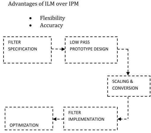
Insertion Loss Method. Advantages of ILM over IPM
Flexibility
[image:4.595.293.549.486.710.2] Accuracy
Figure 1.3: Procedure for Band Pass Filter Design.
SPECTRUM
ANALYZER
FILTER SPECIFICATION
OPTIMIZATION
FILTER
IMPLEMENTATION LOW PASS PROTOTYPE DESIGN
© 2016, IRJET | Impact Factor value: 4.45 | ISO 9001:2008 Certified Journal
| Page 1183
FORMULA
C = g/Ro
c
L = Rog/
c
L = Ro L
C = C/ Ro
Rs = Ro
RL = Ro RL
SPECIFICATION
Operating frequency: 50 MHz
Upper frequency: 30 MHz
Lower frequency: 0.15 MHz
PL = / c
PL = 50 MHz / (30-0.15) MHz = 0.6
Attenuation: 30 dB
ORDER N= 7
RESPONSE: Maximally Flat Response
Simulation & Results
Advanced Design System is the world’s leading electronic design automation software for RF, microwave, and high speed digital applications. In a powerful and easy-to-use interface, ADS pioneers the most innovative and commercially successful technologies, such as X-parameters* and 3D EM simulators, used by leading companies in the wireless communication & networking and aerospace & defense industries.
[image:5.595.308.552.178.382.2]TOOLS FOR IMPLEMENTATION
Figure 1.4: ADS R2011.01. Simulation Design
The Key benefits of ADS are complete, integrated set of fast, accurate and easy-to-use system, circuit & EM simulators enable first-pass design success in a complete desktop flow. Application specific Design Guides encapsulate years of expertise in an easy-to-use interface. [11] It is
supported exclusively or months earlier than others by
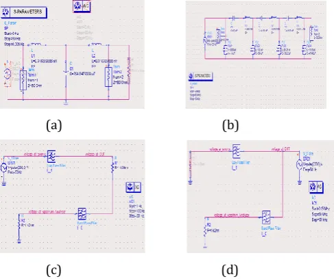
leading industry and foundry partners. Using ADS software the RF Filter was designed as schematic diagram to simulate the design based on the manual calculations using formulas. Finally the low pass and band pass filter are converted into symbol with load and resistance values.
(a) (b)
(c) (d)
Figure 1.5: Simulation Design: (a) Low Pass Filter Design, (b) Band Pass Filter Design, (c) LISN Design( Power Supply), (d) LISN Design(DUT).
Simulation Results
The simulation results of proposed LISN with the following specification are given below.
(a) (b)
[image:5.595.306.520.508.746.2]© 2016, IRJET | Impact Factor value: 4.45 | ISO 9001:2008 Certified Journal
| Page 1184
Figure 1.6: Simulation Results: (a) Low Pass Filter Output 50 HZ, (b) Band Pass Filter Output 0.15-30 MHz, (c) LISN Output at power supply, (c) LISN Output at DUT.
SPECIFICATION OF PROPOSED LISN DESIGN
Frequency Range: 0.15 MHz-30 MHz
LISN Impedance: (50 µh + 5 ǀǀ 50) Ohm
Maximum Continuous Current: 10 A
Maximum Voltage: 230 V
Standard: CISPR-22
Supply Cable: IEC
Impedance Matching: Probing Technique
Conclusion
In this research work from all of the experimental results, it can be concluded that the proposed LISN can be provided the defined impedance 50 ohm and RF coupling signal as the functions of commercial LISN with a cheaper cost due to removal of the selector switch and transient limiter .A low cost LISN is built using components that are easily available in laboratory. The laboratory built LISN bill of materials costs about Rs.8k.This is less than 15% of the case of commercial LISN of similar voltage and current rating. Finally the proposed LISN has tested with continuous 1 Ω R at EUT connector. The measured temperature at all devices is less than the temperature limit of devices. The set-up is evaluated analytically and experimentally.
The test provides a good assessment of the EMI characteristics of the Information Technology Equipment. However, the future work will concentrate on the design of 3-phase LISN for lightening arrestors with low cost to experience better accuracy and efficiency.
Acknowledgment
It is a matter of great pleasure by getting the opportunity of highlighting a fraction of knowledge, I acquired during our technical education through this paper. I would express my profuse thanks to our head of the department and all staff members of ECE department who have helped for the successful completion of this paper.
References
[1] Chetan Kathalay,(2015) “A practical approah to EMC “ by EMC
Publications,pune,Edition 1.
[2] Clayton R Paul,(2006) “Introduction to EMC”, Second Edition,John
Wiley and sons,Inc. Publication,.
[3] Costa(2014) EMC in Power Electronics,USA WILEY.
[4] Francois Ziade, (February 2016) “Improvement of LISN Measurement Accuracy Based on Calculable Adapters” in IEEE Transactions on
Instrumentation and Measurement, Vol. 65, No. 2.
[5] Grobler, “Low cost power lead extended pre-compliance conducted EMI measurement setup and diagnostics with compact LISN” in 10.1109/ECCE-Asia.2013.6579252.
[6] Grobler, “Low cost power lead extended pre-compliance conducted EMI measurement setup and diagnostics with compact LISN” in 10.1109/ECCE-Asia.2013.6579252.
[7] Henry W.Ott, (2009) “Electromagnetic Compatibility Engineering”,
Wiley Publication,.
[8] Kang-Rong Li, (2016) “Impact Analysis of Conducted Emission
Measurement without LISN” in IEEE Transactions on Electromagnetic
Compatibility, Vol. 58, No. 3, June.
[9] Shreenivas Jog, (2015) “Electromagnetic Compatibility of Energy Efficient SMPS with CISPR EMI Standards” in International Conference on Energy Systems and Applications ICESA.
[10]Takashi Shinozuka, “Calibration Methods for AC-Coaxial Adapter Used in AMN Impedance Measurements” in IEEE Transactions on
Electromagnetic Compatibility.
[11]V.Tarateeraseth, K. Y. See, Canavero, and K.C.A Chang, (2010)
“Systematic electromagnetic interference filter design based on information from in-circuit impedance measurements,” IEEE Trans.
Electromagnetic Compatibility, vol. 52, no. 3, pp. 588– 598.
© 2016, IRJET | Impact Factor value: 4.45 | ISO 9001:2008 Certified Journal
| Page 1185
Network” in Microwave, Antenna, Propagation and EMC Technologies for Wireless Communications, 3rd IEEE
International Symposium
10.1109/MAPE.2009.5355743.
[13]Yi Sun, (2009) “Development of a New Line Impedance Stabilization Network” in Microwave, Antenna, Propagation and EMC Technologies for Wireless Communications, 3rd IEEE International Symposium 10.1109/MAPE.2009.5355743.
[14]Y. Yorozu, M. Hirano, K. Oka, and Y. Tagawa, “Electron spectroscopy studies on magneto-optical media and plastic substrate interface,” IEEE Transl. J. Magn. Japan, vol. 2, pp. 740-741, August 1987 [Digests 9th Annual Conf. Magnetics Japan, p. 301, 1982].