© 2017, IRJET | Impact Factor value: 5.181 | ISO 9001:2008 Certified Journal | Page 1271
Analysis of a RCC frame Tall Structure using Staad Pro on Different
Seismic Zones Considering Ground Slopes
Rajkumar Vishwakarma
1, Anubhav Rai
21
M-Tech Student, Department of Civil Engineering, Gyan Ganga Institute of Tech. & Science, Jabalpur M.P. India
2Asst. Professor, Department of Civil Engineering, Gyan Ganga Institute of Tech. & Science, Jabalpur M.P. India
---***---Abstract –
The hilly areas in north east India contained
seismic activity. Due to hilly areas building are required
to be constructed on sloping ground due to lack of plain
ground. The buildings are irregularly situated on hilly
slopes in earthquake areas therefore many damages
occurred when earthquake are affected, this may be
causes lot human disaster and also affect the economic
growth of these areas... In this paper we analyzed using
Staad Pro comparison between sloping ground, with
different slope and plain ground building using Response
Spectrum Method as per IS 1893-2000 The dynamic
response, Maximum displacement in columns are
analyzed with different configurations of sloping ground.
Keywords— Seismic, Multistoried building, Sloping ground
I Introduction
[image:1.595.311.562.229.500.2]India has track record of catastrophic earthquakes, at various regions, which left behind loss of many lives and heavy destruction to property and economy. Investigation of buildings in hilly region is somewhat different than the buildings on leveled ground, since the column of the hill building rest at different levels on the slope. Such building have mass and stiffness varying along the vertical and horizontal planes resulting the center of mass and center of rigidity do not coincide on various floors, hence they demand torsional analysis, in addition to lateral forces under the action of earthquakes. The unsymmetrical building require great attention in the analysis and design under the action of seismic excitation. Past earthquake in which, buildings located near the edge of a stretch of hills or on sloping ground suffered serious damages. The shorter column attracts more forces and undergoes damage, when subjected to earthquakes. The other problems associated with hill buildings, additional lateral earth pressure at various levels, slope instability, different soil profile yielding unequal settlement of foundation.
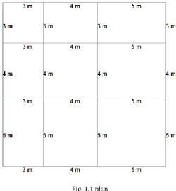
Fig. 1.1 plan
STRUCTURAL MODELLING A RCC medium rise building of 10 stories with floor height 3 m subjected to earthquake lading in V has been considered. In this regard STAAD Pro V8i software has been considered as tool to perform. Effect of sloping effect of the ground on behaviour of structural frames is analysed.
The plan for the above building shown in figure has been considered to carry out the study the dimension of the building are 12m x 12m. Generally in such cases the building is to be analysed for the earthquake force because maximum lateral force induced in building is due to earthquake load. The structural effect of the building on various sloping ground is to be studied.
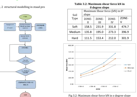
© 2017, IRJET | Impact Factor value: 5.181 | ISO 9001:2008 Certified Journal | Page 1272 Fig. 2 structural modelling in staad pro
Result analysis-
[image:2.595.76.226.114.403.2]
Maximum displacement (mm)
Table 3.1: Maximum displacement in 0 degree slope
Soil Type
Maximum displacement (mm) in 00 sloping ground in X direction
[image:2.595.308.559.158.381.2]ZONE-II ZONE-III ZONE-IV ZONE-V Soft 100.03 158.77 237.10 354.58 Medium 81.86 131.70 193.48 291.10 Hard 60.75 95.93 142.83 213.18
Fig 3.1: Maximum displacement in 0 degree slope
Table 3.2: Maximum shear force kN in 0 degree slope
Soil Type
Maximum Shear force (kN) in 00 slope
ZONE-II ZONE-III ZONE-IV
ZONE-V
Soft
158.5
231.9
331.8
474.7
Medium
135.8
195.0
273.3
396.9
Hard
111.5
153.4
212.0
301.9
[image:2.595.90.563.403.736.2] [image:2.595.304.558.417.720.2]© 2017, IRJET | Impact Factor value: 5.181 | ISO 9001:2008 Certified Journal | Page 1273
Table 3.3: Maximum Bending moment (kN-m) in 0 degree slope
Soil
Type
Maximum Bending Moment (kN-m) in 00 sloping ground
Zone-II Zone-III Zone-IV Zone- V
Soft
209.45 324.76 477.88 718.66 Medium 175.08 267.18 392.3 584.5 Hard 141.22 201.42 295.76 430.62Fig 3.3: Maximum bending moment (kNm) in 0 degree slope
Max Displacement in 7 degree slope-
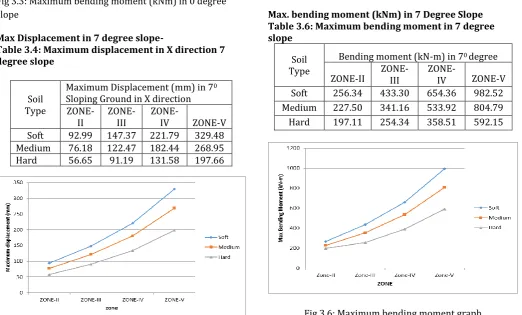
Table 3.4: Maximum displacement in X direction 7 degree slope
Soil Type
Maximum Displacement (mm) in 70 Sloping Ground in X direction
ZONE-II ZONE-III ZONE-IV ZONE-V Soft 92.99 147.37 221.79 329.48 Medium 76.18 122.47 182.44 268.95
[image:3.595.34.569.114.740.2]Hard 56.65 91.19 131.58 197.66
Fig 3.4: Maximum displacement
[image:3.595.47.555.129.388.2]Maximum shear force in 7 degree slope
Table 3.5: Maximum shear force in 7 degree slope
Soil Type
Maximum Shear force (kN) in 70 slope
ZONE-II ZONE-III ZONE-IV ZONE-V Soft 300.137 461.214 681.381 101.631 Medium 250.543 381.175 557.893 824.40
[image:3.595.308.558.130.384.2]Hard 192.922 287.963 417.035 612.76
Fig 3.5 : Maximum shear force graph
Max. bending moment (kNm) in 7 Degree Slope Table 3.6: Maximum bending moment in 7 degree slope
Soil Type
Bending moment (kN-m) in 70 degree
[image:3.595.37.298.135.394.2]ZONE-II ZONE-III ZONE-IV ZONE-V Soft 256.34 433.30 654.36 982.52 Medium 227.50 341.16 533.92 804.79 Hard 197.11 254.34 358.51 592.15
[image:3.595.40.563.411.726.2]© 2017, IRJET | Impact Factor value: 5.181 | ISO 9001:2008 Certified Journal | Page 1274
[image:4.595.202.548.126.377.2]Max displacement (mm) in X direction.
Table 3.7: Maximum displacement in 14 degree slope
Soil Type
Maximum displacement (mm) in 140 sloping ground in x direction
ZONE-II ZONE-III ZONE-IV ZONE-V Soft 97.85 154.79 233.05 351.93 Medium 82.92 127.11 191.02 285.40
Hard 63.11 97.37 143.06 212.45
Fig 3.7: Maximum displacement
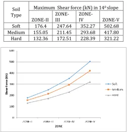
Max Shear Force in 14 Degree Slope
Table 3.8: Maximum shear force in 14 degree slope
Soil Type
Maximum Shear force (kN) in 140 slope
[image:4.595.37.293.132.383.2]ZONE-II ZONE-III ZONE-IV ZONE-V Soft 176.4 247.64 352.27 502.68 Medium 155.05 211.45 293.68 417.80 Hard 132.36 172.51 228.39 321.22
Fig 3.8: Maximum shear force graph
3 Max. bending moment (kNm) in 14 Degree Slope Table 5.25: Maximum bending moment in 14 degree slope
Soil Type
Max bending Moment (kNm) in 140 sloping slope
ZONE-II ZONE-III ZONE-IV ZONE-V Soft Zone-II Zone-III Zone-IV Zone-V Medium 255.41 360.82 544.64 820.35 Hard 229.19 298.38 442.25 666.82
Fig 5.25: Maximum bending moment graph
Conclusion-
As per the results
Results shows that as the slope is increasing bending moment is also increasing also as the effect of soil and seismic zones shows their impact.
Shear force is increasing as seismic zones are increasing also the soil is also showing its effects.
As the slope is increasing displacement is increasing.
REFERENCES
[1] Sujit kumar, vivek garg, abhay sharma. “Effect Of Sloping Ground On Structural Performance Of RCC Building Under Seismic Load”, International journal of sciences, engineering and technology, ISSN: 2348-4098, Volume 2, Issue 6, 2014
[2] Umakant Arya, Aslam Hussain, Waseem Khan, “Wind Analysis of Building Frames on Sloping Ground”. International Journal of Scientific and Research Publications,Issn 2250-3153 Volume 4, Issue 5, May 2014.
[image:4.595.35.288.451.715.2]© 2017, IRJET | Impact Factor value: 5.181 | ISO 9001:2008 Certified Journal | Page 1275 [4] Paul D.K. and Kumar S. Stability Analysis of Slope with
Building Loads. Soil Dynamics and Earthquake Engineering, 16, 395-405,(1997).
[5] Vijaya Narayanan, et. al, “Performance of RC Buildings along Hill Slope of Himalaya during 2011 Sikkim Earthquake”, EERI Newsletter, EERI Special Earthquake Report, 1-14, February 2012.
[6] Dr. S. A. Halkude, Mr. M. G. Kalyanshetti, Mr. V. D. Ingle “Seismic Analysis of Buildings resting on sloping grounds with varying Number of bays and hill Slopes”, International Journal of Engineering Research and Technology, ISSN: 2278-0181, VOL 2, ISSUE 12, December 2013.
[7] Nalawade.“ Seismic Analysis of Buildings on Sloping Grounds,” University of Pune, M.E.dissertation, December 2003.
[8] S.M.Nagargoje et al," Seismic performance of multstoreyed building on sloping ground”. elxir international journal, December 2012.
[9] D.K. Paul, “seismic analysis of framed buildings on hill slopes”, Bulletin of the Indian Society of Earthquake Technology, ISSN:335, vol 30, pp. 113-124,December 1993.
[10] G.Suresh, “Seismic Analysis o f Buildings Resting on Sloping Ground and Considering Brace System” international journal of engineering research & technology,Vol.3,ISSUE 9,ISSN:2278:0181, , September 2014.
.
[11] Satish Kumar and D.K. Paul3, Hill building configurations from seismic considerations, Journal of structural engineering , vol. 26, No. 3, Oct. 1999.
[12] B.G. Birajdar and S.S. Nalawade5, Seismic analysis of buildings resting on sloping ground, 13th world conference on earthquake engineering, Vancuover, B.C., Canada, August 1-6, 2004, paper No. 1472.
[13] Fuji, K., Nakano, Y. and Sanada, Y. (2004), “Simplified Nonlinear Analysis Procedure for Asymmetric Buildings”, Proc. of the 13th World Conference on Earthquake Engineering, Vancouver, Canada, Paper No. 149
[14] Sharad Sharma (2008), “Seismic soil-structure interaction in buildings on hilly slopes” M.Tech. Dissertation, Indian Institute of Technology Roorkee.
[15] Dr. B.G. Naresh Kumar and Avinash Gornale Seismic Performance Evaluation of Torsionally Asymmetric Buildings International Journal of Science and Engineering Research, bVolume 3, Issue 6, June 2012.
[16] Pandey A.D, Prabhat Kumar, Sharad Sharma Seismic soil structure interaction of buildings on hill slopes International