Abstract—In this paper, two compact architectures for hardware implementation of Advanced Encryption Standard S-box are presented based on a polynomial basis and a normal basis, respectively. Composite Field Arithmetic is employed in these architectures to reduce the area consumption and shorten the critical path. Furthermore, a novel Multi-Variable Patterns Common Subexpression Elimination algorithm is proposed to further optimize the S-box, which efficiently reduces the redundant resources of multiplicative inversion in GF(24)
module and isomorphism mapping functions. It is shown that both optimized S-boxes have good area-delay performances, and that the normal basis S-box uses 20.4% less XOR and a shorter critical path compared with the polynomial basis S-box. In 0.18µm COMS technology, the normal basis S-box has the smallest area-delay product, which is 10.32% and 19.64% smaller than that of the smallest area S-box and the shortest critical path S-box, respectively.
Index Terms—AES, S-box, Composite Field Arithmetic (CFA), Multi-Variable Patterns Common Subexpression Elimination (MVP-CSE) algorithm, polynomial basis, normal basis.
I. INTRODUCTION
Advanced Encryption Standard (AES) encryption algorithm is established by the National Institute of Standards and Technology (NIST) to replace the original DES encryption algorithm in 2001 [1]. It is one of the most important symmetric block ciphers. The block length of the AES algorithm is 128 bits with the key lengths of 128, 192 or 256 bits. Full computation of the AES encryption requires 10, 12 or 14 iterations, each containing four transformations: SubBytes, ShiftRows, MixColumns and AddRoundKey. The SubBytes transformation, commonly known as S-box, is a nonlinear substitution that guarantees a better security of the AES encryption. It takes the most resource and consumes the most power in the implementation. Hence, the hardware implementation efficiency of the AES encryption in terms of area, speed, security and power consumption mainly depends on the implementation of S-box [2].
In general, the AES encryption is applied in
This work was supported by the National Natural Science Foundation of China (61376025), Industry-academic Joint Technological Innovations Fund Project of Jiangsu Province (BY2013003-11) he Funding of Jiangsu Innovation Program for Graduate Education (No. KYLX_0273), and the Fundamental Research Funds for the Central Universities.
Xiaoqiang ZHANG is with the College of Electronic and Information Engineering, Nanjing University of Aeronautics and Astronautics (NUAA), Nanjing 210016, China (e-mail: [email protected]).
Ning WU is with the College of Electronic and Information Engineering, NUAA, Nanjing 210016, China (e-mail: [email protected]).
Chun ZENG is with the College of Electronic and Information Engineering, NUAA, Nanjing 210016, China (e-mail: daisyzeng0407201@ 126.com).
resource-limited systems, where the area optimization of the AES hardware implementation is highly desirable. Several small-area S-box designs using CFA constructions are proposed in [2]-[10], and they usually base on polynomial basis and normal basis. Summarizing from the previous works [2]-[10], Canright [3] presented the smallest S-box based on normal basis. However, the critical path was long in Canright’s work. On the other hand, Zhang [8] proposed an AES S-box based on polynomial basis with the shortest critical path to date [5]. However, their work requires a large area.
In this paper, both area and critical path of S-box implementation are taken into account, with the focus on approaches to implement a very compact S-box efficiently. To reduce the hardware resource requirement of the S-box, we use pure combinational-logic through exploitation of Composite Field Arithmetic (CFA) in GF(((22)2)2). A new MVP-CSE algorithm is proposed for subexpressions sharing. In Section II, two S-box circuit structures are derived, one based on the polynomial basis, and the other, the normal basis. In Section III, the squarer module and the constant multiplier module in GF(24) are merged into a single one by using CFA, to reduce the gate counts significantly, while the critical path is shortened greatly. To optimize the multiplicative inversion circuit in GF(24) and isomorphism mapping function circuit of the S-boxes, a new Multi-Variable Patterns Common Subexpression Elimination (MVP-CSE) algorithm is proposed in Section IV. In Section V, the evaluation of the resulting S-boxes and the comparison with previous works are discussed. Conclusions are given in Section VI.
II. COMPOSITE FIELD IMPLEMENTATION OF S-BOX The AES S-box is defined as the multiplicative inversion module in the finite field GF(28) followed by an affine transformation [11]. The S-box is calculated by using (1).
T T
T M X V
F = (( )−1)+ (1)
where X is the input state matrix. M is an 8×8 constant matrix, defined as M=[0x8E, 0xC7, 0xE3, 0xF1, 0xF8, 0x7C, 0x3E, 0x1F]. V is an 8-bit constant vector, defined as V=[0x63]. The row vectors of both M and V are represented in the hexadecimal format. The process of affine transformation is defined as follows: X-1 is multiplied by M first, then combined with a constant vector V in the affine transformation.
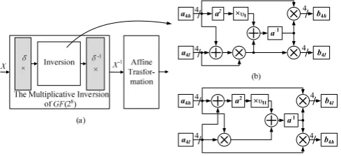
This study focuses on approaches to deduce and simplify the multiplicative inversion in GF(28). Fig.1 shows the implementation block diagram of the S-box using the CFA technique (Fig.1(a)), the multiplicative inversion circuit structure based on the polynomial basis (Fig.1(b)), and Xiaoqiang ZHANG, Ning WU, Chun ZENG
normal basis (Fig.1(c)). Based on the CFA technique, the S-box can also be calculated by using (2). Two parts are included in deriving the multiplicative inversion in GF(28): one is the derivation of an inversion module in the composite field GF(((22)2)2), and the other is the calculation of mapping matrices δ and δ-1 in isomorphism mapping functions. The mapping matrices δ and δ-1 are the linear transformations between the finite field GF(28) and the composite field GF(((22)2)2).
T T
T M X V
F = (δ−1(δ )−1)+ (2)
According to Fig.1(a), δ is the mapping matrix from the finite field to the composite field, and δ-1 is the inverse of δ. The relationship between δ and δ-1 is δ×δ-1=E, and E is a unit matrix. Usually, the mapping matrix δ-1 can be combined with the affine matrix M to simplify the circuit structure of the S-box. For easy presentation, the polynomial basis S-box is denoted as Case I, and the normal basis S-box, as Case II.
The structures of the inversion module and the value of the mapping matrix can be derived based on the irreducible polynomial coefficients of the composite field GF((22)2) and GF((24)2). The irreducible polynomial of the composite field GF((24)2),GF((22)2) and GF(22) operation are denoted as follows:
2 2 2 2
2 2 2
2 2
(((2 ) ) ) : ( ) ((2 ) ) : ( )
(2 ) : ( ) 1
GF f y y y
GF f z z z
GF f w w w
τ υ
⎧ = + +
⎪
= + Τ + Ν
⎨
⎪ = + +
⎩
(3)
where τ=(0001)4 , Т=(01)2, and υI=(1100)4, ΝI=(10)2 in Case I [3], υII=(0001)4, ΝII=(10)2 in Case II [4].
According to the selected coefficients τ, υ, Т, Ν, the inversion module in Case I can be calculated by using (4), and that in Case II, by using (5). The inversion structure in Case I is shown in Fig. 1(b), and that in Case II, in Fig. 1(c).
)) (
( )) (
( 1 4 4 4
4 4 4 2 4 1
h l h
h l l I h
I a a a a a X a a
A− = υ + + − + + (4)
) (
) )
(( 16 4
4 1 4 4 2
4 2 4
1 a a a a a Y a Y
AII− = l+ hυII + l h − l + h (5)
where AⅠ∈GF(28), a4h,a4l∈GF(24); AⅡ∈GF(28), a4h,a4l∈
GF(24). In (4), the basis (X,1) is chosen in the composite field GF ((24)2). In (5), the basis (Y16, Y) is chosen.
The irreducible polynomial P(x) =x8+x4+x3+1 in GF(28) is
selected in the AES encryption, whereas the δ and δ-1 can be calculated by using the CFA technique according to the following equations:
1
[0 2,0 4 ,0 78,0 63,0 75,0 35,0 7 ,0 05] [0 ,0 0 ,0 79,0 7 ,0 6 ,0 46,0 22,0 47] I
I
xC x A x x x x x B x xAE x C x x C x E x x x
δ
δ −
= ⎧ ⎨
= ⎩
(6)
1
[0 7, 0 71, 0 63,0 1, 0 8 , 0 01, 0 61,0 054 ] [0 12, 0 ,0 ,0 42, 0 7 ,0 2, 0 22, 0 04] II
II
xE x x xE x B x x x F x xEB xED x x E xB x x
δ
δ −
= ⎧
⎨ =
⎩
(7)
To reduce the area and shorten the delay of the S-box, the concrete method can be summarized as follows: Modules ×υ and a2 are merged into one module υ×a2, and a pure combinational-logic expression is derived for a-1 utilizing the CFA technique; then, the proposed MVP-CSE algorithm is used to reduce the gate counts and shorten the critical path in a-1 module, the isomorphism mapping functions, and the affine transformation.
III. CFAOPERATION FOR S-BOX OPTIMIZATION In this section, the detailed architectures are presented to optimize the modules of the ×υ, a2, and the a-1 that are shown in Fig.1(b) and Fig.1(c) of the S-box. Each module’s implementation is derived by using the CFA technique to reduce area and to increase speed. The detailed calculation process of architectures for ×υII and aII2 in Case II is introduced afterwards, and the modules of ×υI and aI2 are optimized in the same fashion.
The multiplications in Fig.1(c) are derived based on the normal basis according to the following equation:
4
4 4 2 2 2 2 2 2
2 2 2 2 2 2
( ) ( ) ( ( )( ) )
( ( )( ) )
h h l h l h
l l l h l h
A Z B Z a b a a b b Z
a b a a b b Z
= + + + Ν
+ + + + Ν (8)
where A4, B4∈GF(24), and they are represented as A4(Z)=a2hZ4+a2lZ, and B4(Z)=b2hZ4+b2lZ, respectively, using the normal basis (Z4,Z). a2h, a2l, b2h, b
2l∈GF(22).
The multiplication in (8) can be decomposed into GF(22) and then further into GF(2). In GF(2), a multiplication is simply an AND gate. According to υII=(0001)4, ΝII=(10)2, the modules ×υII and a2 are computed based on the CFA technique and merged into one single module υII×a2. The υIIa2 can be calculated by using (9).
2 2 4 4
0 0 1 1
2
1 0 0
( ) ( )
( )
II h l h l
l l l
a a a W Z a a WZ
a a W Z a WZ
υ = + + +
+ + + (9)
where the normal basis (W2, W) are chosen in GF(22), and a2h=ah1W2+ah0W, a2l=al1W2+al0W, b2h=bh1W2+bh0W, b2l=bl1W2+bl0W. ah1, al1, bh0, bl0∈GF(2).
[image:2.595.48.293.55.167.2]Fig. 2 illustrates the detailed opeartions of ×υII and a2, together with the merged structure of υII×a2. As observed from Fig. 2, ×υII and aII2 are implemented by 4 XOR gates and 6 XOR gates, respectively, while the merged module υIIa2 only needs 3 XOR gates. Table I summarizes the resource consumption and critical path optimization of ×υ and a2 by using the CFA technique for both Case I and Case II. After Fig.1 Implementations block diagram of S-box: (a) Implementation of S-box
being merged into one module, the υIa2 operation saves 42.9% in the resource consumption and shortens the critical path by 50% in Case I, while the υIIa2 operation saves 70.0% in the resource consumption and shortens the critical path by
75% in Case II.
The expressions structures of the inversion circuits aI-1 and aII-1 in GF(24) shown in Fig. 2(a) and Fig. 2(b) are similar to those of (4) and (5).Similar to Eqs. (8) and (9), aI-1 and aII-1 can be represented as follows:
)) (
( )) (
( 2 2 2
1 2 2 2 2
2 1
h l h h l l I h
I a a a a a X a a
a− = Ν + + − + + (10)
) (
) )
(( 4 2
2 1 2 2 2
2 2 2
1 a a a a a Z a Z
aII− = l+ h ΝII + l h − l + h
(11)
To further simplify calculations, we substitute ΝI=(10)2 into (10), and ΝII=(10)2 into (11). The direct implementations of the resulting equations for aI-1 and aII-1 are given by (12) and (13).
IV. MVP-CSEALGORITHM FOR SUBEXPRESSIONS SHARING OPTIMIZATION IN S-BOX
The subexpressions can be shared to reduce the
complexity of the a-1 module in GF(24), the mapping function δ× module, and the combined inverse mapping and affine transformation Mδ-1× module in S-box. The approach to select a subexpression for sharing can be described as identifying patterns. A single variable is used to replace the identified pattern. In [12], it has been proven that selecting a pattern to eliminate is an NP-complete problem. To find an optimal solution, the proposed MVP-CSE algorithm for S-box optimization focuses on the number of variables in each candidate pattern. It employs an exhaustive search algorithm for the situation that several patterns can be selected for elimination. As a result, the MVP-CSE algorithm is efficient and yields a better solution.
A. MVP-CSE Algorithm
In the MVP-CSE algorithm, the patterns with most variables are extracted at each iteration. If there are more than one pattern, the patterns with the highest frequency of occurrences will be selected. From the highest occurrence patterns, an exhaustive search algorithm is employed to extract each of them and replace the pattern with a new variable. The process continues until no more common subexpressions are found. The detail of the MVP-CSE algorithm is summarized in Fig. 3.
Fig.2 The process for merging modules: (a)×υ; (b) a2 ; (c)υ II×a2
TABLE I
THEOPTIMIZATION OF ×υ AND a2 OPERATION
Approach ×υ AND a2 Resource
Consumption Critical Path Separate 7 XOR 4 XOR Case I
Merged 4 XOR 2 XOR Separate 10 XOR 4 XOR Case II
Merged 3 XOR 1 XOR
Fig.3 Flowchart of MVP-CSE algorithm
1
1 0 1 1 0 1 0 1
1 0 1 1 0 0 1 0 0 1 0 0
1
1 1 0 1 1 1 0 1 1 0 0 1 0 1
0 1 0 1 1 0 0 1 1 0 0 1 0 1 0 0 1 0 1
h h l h l h h
h
h h l h h l h l h l h
h I
l h h l h l l h l h l h h l
l h h l h h l h l l h l l h l h l h l
a a a a a a a a
a a a a a a a a a a a a
a
a a a a a a a a a a a a a a
a a a a a a a a a a a a a a a a a a a
− −
+ + +
⎛ ⎞
⎜ ⎟ + + + +
⎜ ⎟
=⎜ ⎟ =
+ + + + + +
⎜ ⎟
+ + + + + + + +
⎝ ⎠ al0
⎛ ⎞
⎜ ⎟
⎜ ⎟
⎜ ⎟
⎜ ⎟
⎜ ⎟
⎝ ⎠
(12)
1
0 1 0 1 1 0 1 1 0 1
1 1 0 1 1 0 1 0 0 0 0
1
1 1 0 0 1 1 1 0 1 0
0 1 0 1 1 1 1 0 0 0 0
h l l h l h l l l
h
h l l h l h l h l l
h II
l h h l h l h l h h
l h h l h l h l h l h
a a a a a a a a a a
a a a a a a a a a a a
a
a a a a a a a a a a
a a a a a a a a a a a
− −
+ + + +
⎛ ⎞
⎛ ⎞
⎜ ⎟
⎜ ⎟ + + + +
⎜ ⎟
⎜ ⎟
=⎜ ⎟ =⎜ ⎟
+ + + +
⎜ ⎟
⎜ ⎟ ⎜ ⎟
+ + + +
⎝ ⎠ ⎝ ⎠
For example, considering the constant multiplication matrix [0x9, 0xf, 0xf, 0x5], the MVP-CSE algorithm is applied to the matrix in (14). According to the flowchart in Fig. 3, the algorithm identifies the patterns “x4+x3+x2” to be eliminated at the first iteration. A new variable “b1” is generated to replace the pattern “x4+x3+x2”. In the second iteration, “x3+x2” has the highest frequency of occurrences, and it is identified and replaced by a new variable “b2”. The computation process can be expressed as follows:
4 4
3 3
2 2
1 1
4 3 2 1
3 2 1 2 1
3 2 2
1 1 4 3 2 1
1 4 3 2 2 3 2 1 1 1 0 0 1 1 0 0 0 1 1 1 1 1 1
;
y x
y x
y x
y x
x x x b
x x x b x
x x b
b x
x x x x
b x x x b x x
⎡ ⎤ ⎡ ⎤ ⎡ ⎤ ⎢ ⎥ ⎢ ⎥ ⎢ ⎥ ⎢ ⎥=⎢ ⎥×⎢ ⎥ ⎢ ⎥ ⎢ ⎥ ⎢ ⎥ ⎢ ⎥ ⎢ ⎥ ⎢ ⎥ ⎣ ⎦ ⎣ ⎦ ⎣ ⎦ + + ⎡ ⎤ ⎡ ⎤ ⎢ + + ⎥ ⎢ + ⎥ ⎢ ⎥ ⎢ ⎥ = = ⎢ + ⎥ ⎢ ⎥ ⎢ + + + ⎥ ⎢ + ⎥ ⎣ ⎦ ⎣ ⎦ = + + = + (14)
B. The MVP-CSE for inverse a-1 module in GF(24)
According to (12) in section III, the resource consumption of the aI-1 module is 21XORs+25ANDs. The aII-1 module
needs 18XORs+16ANDs in (13). The MVP-CSE method can be employed to optimize both the XOR gates and AND gates by using the same selection rules. The computation process of applying the MVP-CSE to (12) and (13) can be expressed as:
1 1 0 1 0 1 0 1 2
2 1 0 0 0 1 3 1
1 1 1 0 1 4 1 1 0 0 1
3 4 0 1 0 0
1 1 0 1 1 0 1 2 0 1 2
2 1 0 2 3
1 1 1 1
( ( ) ) ( ) ( ) (( ) ( ( ) ) ) ( ) (
h h l h h l h b b
h h l h l b I
h l l l b h l h l h
h l l l
h h l c h h l c h b b
h b
l l
a a a a a a a b a a a a a a
b a a a a a a a a a b b a a a a
a a a a a a a b c a c
b c a a − + + + ⎛ ⎞ ⎜ + + ⎟ ⎜ ⎟ =⎜ ⎟ + + + + + ⎜ ⎟ ⎜ + + + ⎟ ⎝ ⎠ + + + + + =
+ + 4 1 1 0 0 1
3 4 2 0 0
)b h l h l h
l l
a a a a a b b c a a
⎛ ⎞ ⎜ ⎟ ⎜ ⎟ ⎜ + + + ⎟ ⎜ ⎟ ⎜ + + + ⎟ ⎝ ⎠ (15)
0 1 0 1 1 0 1 0 1 1
1 1 1 0 0 0 1
1 0 0 1 1 1 0 0 2 1
2 1 0 1 0 0
0 1 3 0 1 1 1 3 0 1 1
1 1 0 0 0 4
1 0 2 0
( )
( )
( ) (( ) )
( )
( )
h l l h l h l l b l
h l l h l II
h h l h l h l h b h
h h l h l
h l c l h l c l b l
l h l c
h l c h
a a a a a a a a a b a a a a a
a
a a a a a a a a a b a a a a a
a a a a a c a a b c a a a
a a a − + + + + ⎛ ⎞ ⎜ + + ⎟ ⎜ ⎟ =⎜ ⎟ + + + + ⎜ ⎟ ⎜ + + ⎟ ⎝ ⎠ + + + + + + =
1 2 0 2 1
2 1 0 4
( h )b h
h
c c a a b c a c
⎛ ⎞ ⎜ ⎟ ⎜ ⎟ ⎜ + + + + ⎟ ⎜ ⎟ ⎜ + + ⎟ ⎝ ⎠ (16)
The XOR gates are optimized firstly, then the AND gates, by utilizing the MVP-CSE. As a result, the optimized
multiplicative inversions in GF(24) have a good area performance. Case I only needs 13XORs + 8ANDs, eliminated 38.1% XOR gates and 68.0% AND gates compared with (12). Case II needs only 12XORs +8ANDs, eliminating 33.3% XOR gates and 50.0% AND gates compared to (13).
Compared with the works of [3], [5]-[6], [8], the resource consumption and critical path of multiplicative inversions in GF(24) are shown in Table II. The area-delay in Case II is used as the basic unit for reference.
Table II shows that Case II has the best performance in area-delay and the shortest critical path. The reference [3] presented the smallest multiplicative inversion in GF(24), but a long critical path.
C. The MVP-CSE for δ-1× and Mδ-1× functions
According to the section II, the implementation of S-box includes two parts, namely the multiplicative inversion in GF(28) and the affine transformation. The multiplicative inversion in GF(28) can be decomposed into the ones in GF((24)2), which includes the isomorphism mapping
TABLE II
THE RESOURCES CONSUMPTION AND CRITICAL PATH IN GF(24) MULTIPLICATIVE INVERSION
Approach Consumption Resources Critical Path
XOR AND XOR AND
Area-delay
[3] 9 2NOR+ 2NAND+
6AND
5 2 1.53
[5]case
III 13 9 5 2 1.91
[6]case
III 13 9 3 1 1.09
[8] 14 8 3 2 1.41 case I 13 8 3 2 1.32 case II 12 8 3 1 1
7 6 1
7
6 3 1 6
6 5 4 3 0
5
6 5 1 0
4
3 6 5 4 2 0
2 5 4 2
1
0
1 1 0 0 0 0 1 0 0 1 0 0 1 0 1 0 0 1 1 1 1 0 0 1 0 1 1 0 0 0 1 1 0 1 1 1 0 1 0 1 0 0 1 1 0 1 0 1 0 1 1 1 1 0 1 1 0 0 0 0 0 1 0 1 I
x x x x
x x x x
x x x x x x
x x x x x
X
x x x x x x x x x x
x x δ + + ⎡ ⎤ ⎡ ⎤ ⎢ ⎥ ⎢ ⎥ + + ⎢ ⎥ ⎢ ⎥ ⎢ ⎥ + + + + ⎢ ⎥ ⎢ ⎥ ⎢ ⎥ + + + ⎢ ⎥ ⎢ ⎥ =⎢ ⎥⎢ ⎥= + + + + ⎢ ⎥ ⎢ ⎥ + + ⎢ ⎥ ⎢ ⎥ ⎢ ⎥ ⎢ ⎥ ⎢ ⎥ ⎢ ⎥ ⎢ ⎥ ⎢ ⎥ ⎣ ⎦ ⎣ ⎦
7 6 1 4
4 3
6 3 3 1
4 5 0 5
6 2
0 5 4 3 2 2
6 5 4 3 1 0 1 1
2 0 2 0
( ) ( ) ( ) (( ) ) y y y y y
x x x y x
x x y y x x x y
x y x x
x x x x x x y x
x x x x
functions and the inversion. The affine matrix M and the mapping matrix δ-1 can be merged into a single matrix Mδ-1.
The matrices MδI-1 in Case I and MδII-1 in Case II are shown
separately in (17).
⎩ ⎨ ⎧
= =
− −
] 52 0 , 32 0 , 6 0 , 8 0 , 8 0 , 41 0 , 88 0 , 28 0 [
] 31 0 , 0 0 , 21 0 , 8 0 , 0 0 , 0 , 81 0 , 3 0 [
1 1
x x D x xF xA x x x M
x F x x xC xE xBE x xE M
II I
δ
δ (17)
The constant matrices δⅠ, MδⅠ-1, δⅡ and MδⅡ-1 in S-box
are optimized utilizing the MVP-CSE. The process and result of δⅠ optimization are given in (18). The MVP-CSE is also
[image:5.595.331.525.322.468.2]applied to the remaining constant matrices mentioned above in the same fashion as (18).
Table III shows the MVP-CSE optimization results of the matrices δⅠ, MδⅠ-1, δⅡ and MδⅡ-1. The area reductions range
from 23% to 50%, while the critical path delay increases slightly (one extra XOR gate delay in δⅠ).
The reference [5] takes a double-variable pattern CSE algorithm to optimize the mapping matrices, yielding the resource consumption of 29 XORs and the critical path of 6 XORs. For comparison, Case I requires 26 XORs in resource consumption with the critical path of 7 XORs, and Case II needs only 25 XORs in resource consumption with the critical path of 6 XORs. The results show that the case II has a better optimization result than those of Case I and [5]. Compared with [5], Case I saves 10.3% XOR gates with a slight critical path length increase, and Case II reduces 13.8% XOR gates while having the same critical path.
V. IMPLEMENT RESULTS AND ANALYSIS
The performance comparison between Case I and Case II is illustrated in Table IV. Combining with Fig.1, the CFA algorithm is used for the υ×a2 module optimization and the combinational logic expression derivation of the a-1 module. Moreover, the MVP-CSE algorithm is efficient in reducing the redundant resource of the a-1 module and the mapping matrix modules. The results show that, Case II reduces 20.4% XORs in resource consumption with a shorter critical path compared with Case I.
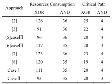
From the performance analysis of Cases I and II, and compared with prior works [2], [3], [5]-[8], the results of resource consumption and critical path are shown in Table V. In the table, a polynomial basis was employed for [2], [7]-[8] as well as Case I. Comparing Case I with [2] and [7], Case I uses less resource and has a shorter critical path. In addition, Case I saves 7.5% XOR gates with a small critical path sacrifice compared with [8]. The normal basis was used in [3], [5] and Case II, whereas [6] combined both polynomial basis
and normal basis for S-box implementation. Case II uses less resource and has a shorter critical path than [5] and [6]. Compared with [3], it shortens the critical path length by 9.1%XORs + 25.0%ANDs with slight larger area consumption. The results show that Case I and Case II optimized by using the CFA and MVP-CSE algorithms achieve a good area-delay performance, since these algorithms consider both area and delay factors comprehensively.
In the 0.18µm CMOS technology, the area consumption is TABLE III
THE MVP-CSEOPTIMIZATION RESULTS FOR δ× AND Mδ-1×FUNCTIONS Without
MVP-CSE (XOR)
With MVP-CSE (XOR) MCM
matrix
Area Delay Area Delay
Optimization Rate
δⅠ 24 3 12 4 50.0%
MδⅠ-1 21 3 16 3 23.8%
δⅡ 24 3 14 3 41.7%
MδⅡ-1 17 3 11 3 35.3%
TABLE IV
THE PERFORMANCE COMPARISON OPTIMIZED AESS-BOXES IN COMPOSITE FIELD COMPUTATION
Inversion of Composite Field Mδ-1 δ S-box
RC CP RC CP RC CP RC CP
Approach
Modules
XOR AND XOR AND XOR XOR XOR XOR XOR AND XOR AND
GF(24) Inversion 13 8 3 2
GF(24)Multiplication 20 9 4 1
υ×a2 4 -- 2 --
CaseⅠ
GF(28) Inversion 85 35 13 4
14 3 12 4 111 35 20 4
GF(24) Inversion 12 8 3 1
GF(24) Multiplication 10 9 4 1
υ×a2 3 -- 1 --
CaseⅡ
GF(28) Inversion 68 35 14 3
14 3 11 3 93 35 20 3
RC: Resources Consumption, CP: Critical Path
TABLE Ⅴ
THE RESOURCES CONSUMPTION AND CRITICAL PATH OF AESS-BOX IN DIFFERENT CASES
Resources Consumption Critical Path Approach
XOR AND XOR AND
[2] 126 36 25 4
[3] 91 36 22 4
[5]caseⅢ 96 36 20 4
[6]caseⅢ 117 35 20 3
[7] 123 36 23 4
[8] 120 35 19 4
CaseⅠ 111 35 20 4
[image:5.595.67.535.623.783.2]26.6112µm2 in a XOR gate and 13.3056µm2 in an AND gate, while the standard delay is 1ns in a XOR gate as well as in an AND gate. Using these parameters, Table VIlists the costs of S-box implementation in [3], [8], Case I, and Case II.
It is observed from Table VI that the area-delay product of Case I is 2.48% less than that of [8], while that of Case II is 10.32% less than that of [3]. The results illustrate that Cases I and II achieves a better performance in the area-delay product, with Case II achieving the best one. For example, Case II saves 17.59%, 10.32%, and 19.64% in the area-delay product, compared to Case I, [3], and [8], respectively.
VI. CONCLUSIONS
This paper discussed the optimization of the compact AES S-box implementation. Two structures of S-box have been proposed based on a polynomial basis and a normal basis, respectively. A CFA algorithm is used to combine ×υand a2 modules to reduce the area-delay product. In addition, a new MVP-CSE algorithm is proposed for subexpressions sharing in mapping functions and a-1 module. As a result, the proposed techniques are efficient in saving the resources and shortening the critical path. Implementing the S-box combinational-logic circuits in 0.18μm COMS technology, the results show that the case based on the normal basis achieves the best area-delay product, saving 17.59%, 10.32%, and 19.64% in the area-delay product, respectively, over the case based on the polynomial basis, [3] and [8].
The combinational-logic circuits of S-box based on either polynomial basis or normal basis are adapted to the pipelined structure, which could further improve the operating frequency of S-box as well as the data throughput. However, high-speed S-box design generally results in a high power consumption. Therefore, future work will be carried out to jointly optimize the speed and power consumption of the S-box hardware implementation.
REFERENCES
[1] National Institute of Standards and Technology (NIST), “Advanced Encryption Standard (AES)”, FIPS Publication 197, Nov. 2001. [2] A. Satoh, S. Morioka, K. Takano, and S. Munetoh, “A compact
Rijndael hardware architecture with S-box optimization”, In Advances in Cryptology-ASIACRYPT 2001, LNCS 2248, 2001, pp. 239–245. [3] D. Canright, “A very compact Rijndael S-box,” Technical report
NPS-MA-04-001, Naval Postgraduate School, 2005
[4] Z. Xinmiao, “High-speed VLSI Architectures for Error-correcting Codes and Cryptosystems,” Ph.D. Minnesota, University of Minnesota, 2005.
[5] M.M.Wong, M.L.D.Wong, A.K.Nandi, I. Hijazin, “Construction of Optimum Composite Field Architecture for Compact High-Throughput AES S-Boxes,” IEEE Transactions on Very Large Scale Integration (VLSI) Systems. vol. 20, no. 6, 2012, pp.1151-1155.
[6] M.M.Wong, M.L.D.Wong, A.K.Nandi, I. Hijazin, “Composite field GF(((22)2)2) Advanced Encryption Standard (AES) S-box with algebraic normal form representation in the subfield inversion,” Circuits, Devices & Systems IET. Vol. 5, Nov. 2011, pp. 471-476. [7] N. Mentens, L. Batinan, B. Preneeland, and I. Verbauwhede, “A
systematic evaluation of compact hardware implementations for the Rijndael S-box,” In Topics in Cryptology-CT-RSA 2005, vol. 3376, 2005, pp. 323-333.
[8] X. Zhang, K. K. Parhi, “On the Optimum Constructions of Composite Field for the AES Algorithm,” IEEE Transactions on Circuits and Systems II: Express Briefs, vol. 53, Oct. 2006, pp.1153-1157. [9] Atri Rudra, Pradeep K. Dubey, Charanjit S. Jutla, Vijay Kumar,
Josyula R. Rao, and Pankaj Rohatgi, “Efficient Rijndael encryption implementation with composite field arithmetic,” In Cryptographic Hardware and Embedded System-CHES2001, LNCS 2162, 2001, pp.171-184.
[10] M. Mozaffari-Kermani, R. Reyhani-Masoleh, “A low-cost S-box for the advanced encryption standard using normal basis,” IEEE Int. Conf. Electro/Information Technology 2009, 2009, pp. 52-55.
[11] A.M. Youssef, S.E. Tavares. “Affine equivalence in the AES round function,” In Discrete Applied Mathematics, vol. 148, no. 2, 2005, pp.161-170.
[12] R. Pasko, P. Schaumont, V. Derudder, S. Vernalde, and D. Durackova, “A new algorithm for elimination of common subexpressions”. IEEE Transactions on Computer-Aided Design of Integrated Circuits and Systems, vol. 18, no. 1, 1999, pp.58-68.
TABLE Ⅵ
THE AREA-DELAY PRODUCTS OF S-BOXES IN 0.18µM CMOS TECHNOLOGY
Approach Delay
(ns) Area(µm