Mahesh et al. World Journal of Engineering Research and Technology
A NOVEL BASED APPEAR FOR RANGE OF CLUSTER HEAD USING
POWER EFFICIENT AND LOAD MATCHING CLUSTER BASED
ROUTING ALGORITHM IN WSN
*B. Mahesh M. E., T. Abinaya M. E. and S. Meena M. E.
Assistant Professor, Department of Electronics and Communication Engineering, Nadar
Saraswathi College of Technology- Theni.
Article Received on 18/11/2017 Article Revised on 09/12/2017 Article Accepted on 30/12/2017
ABSTRACT
Wireless sensor network (WSN) requires robust and energy efficient
communication protocols to minimize the energy consumption as
much as possible. Sensor nodes are resource constrained in term of
energy, processor and memory and low range communication and
bandwidth. However, the lifetime of sensor network reduces due to the
adverse impacts caused by radio irregularity and fading in multi-hop
WSN. Limited battery power is used to operate the sensor nodes and is
very difficult to replace or recharge it, when the nodes die. This will affect the network
performance. A Dual Cluster based resource sharing scheme is proposed as a solution for this
problem. The proposed scheme extends ELC algorithm and enables multi-hop transmissions
among the clusters by incorporating the selection of cooperative sending and receiving nodes.
The performance of the proposed system is evaluated in terms of energy efficiency and
reliability. Simulation results show that tremendous energy savings can be achieved by
adopting hard network lifetime scheme among the Dual Cluster clusters. Due to the limited
energy and communication ability of sensor nodes, it seems especially important to design a
routing protocol for WSNs so that sensing data can be transmitted to the receiver effectively.
An energy-balanced routing method based on forward-aware factor (FAF-EBRM) is
World Journal of Engineering Research and Technology
WJERT
www.wjert.org
SJIF Impact Factor: 4.326*Corresponding Author B. Mahesh M. E. Assistant Professor,
Department of Electronics
and Communication
Engineering, Nadar
Saraswathi College of
I. INTRODUCTION
A Wireless Sensor Networks (WSNs) is a self-organization wireless network system
constituted by numbers of micro sensors with limited energy. They are deployed to monitor
the sensing field and collect information from physical or environmental condition and to
co-operatively pass the collected data through the network to a main location. Due to the
limited energy and communication ability of sensor nodes, it is important to design a network
topology, routing algorithm and protocol for large-scale WSN communication system.
Energy consumption is an important factor in system designs of WSNs. Traditionally, there
are two approaches to accomplish the data collection task: Direct communication, and
Multi-hop forwarding. In one Multi-hop wireless communication, the sensor nodes upload data directly to
the sink, which may result in long communication distances and degrade the energy
efficiency of sensor nodes. On the other hand, in multi-hop forwarding, data are transferred
from the nodes to the sink through multiple relays, and thus communication distance is
reduced. However, since nodes closer to the sink have a much heavier forwarding load, their
energy may be
1.1 Wireless Sensor Network
A typical WSN consists of a number of sensing nodes that collect information from the
surrounding environment and forward it to a collector (referred to as the BS) for further
processing. Sensing nodes are normally small, inexpensive, and have limited processing,
computing and energy resources. Each of the sensing nodes has a data processing unit, a
communication unit and a power unit. Depending on the type of application, these nodes are
equipped with different kinds of sensors, such as temperature, humidity and motion detectors.
The sensors gather information from the environment which will be processed and transferred
to the BS or another node via a wireless link. An example of a WSN is shown in Fig. 1.1 in
which the system components of a sensor node are also illustrated. WSNs have been widely
used in recent years due to the low-cost and ease of deployment. Moreover, a WSN is
1.2. Applications
1.2.1. Area Monitoring
Area monitoring is a common application. In area monitoring, the is deployed over a region
where some phenomenon is to be monitored. A military example is the use of to detect
enemy intrusion a civilian example is the geofencing of gas or oil pipelines. For military
users, a primary focus has been area monitoring. WINS (wireless integrated networked) will
replace single high value assets with large arrays of distributed for both security and
surveillance applications. WINS 1 is smaller and more capable than assets presently in the
inventory. The added feature of robust, self-organizing networking makes WINS deployable
by untrained troops in essentially any situation. Distributed sensing has the further
advantages of being able to provide redundant and hence highly reliable information on
threats as well as the ability to localize threats by both coherent and incoherent processing
among the distributed nodes. WINS will be used in traditional network applications for large
area and perimeter monitoring and will ultimately enable every platoon, squad, and soldier to
deploy networks to accomplish a myriad of mission and self-protection goals. The Rockwell
WINS team has been very active in working with the U.S. Marine Corps and the U.S. Army
to test and continuously refine WINS performance in desert, forest, and urban terrain. For the
urban terrain, WINS will dramatically improve troop safety as they clear and monitor
intersections, buildings, and rooftops by providing continuous vigilance for unknown troop
and vehicle activity.
1.2.3. Air Quality Monitoring
To protect humans and the environment from damage by air pollution, it is of the utmost
importance to measure the levels of pollutants in the air. Real time monitoring of dangerous
gases is particularly interesting in hazardous areas, as the conditions can change dramatically
very quickly, with serious consequences. Environmental magnitudes: Temperature,
Humidity, Light Gas & particle concentration: O2, CO, CO2, SO2, H2S, NO, NO2, NH3,
CH4, PM-10, TVOC. Ambient monitoring: Rainfall, Wind speed, Wind direction, UV levels,
Atmospheric pressure.
1.2.4. Interior Monitoring
The measurement of gas levels at hazardous environments requires the use of robust and
trustworthy equipment that meets industrial regulations.
1.2.5. Exterior Monitoring
Outdoor monitoring of air quality requires the use not only of accurate, but also rain & wind
resistant housing, as well as the use of energy harvesting techniques that ensure extended
autonomy to equipment which will most probably have difficult access.
1.2.6. Air Pollution Monitoring
Wireless ad hoc networks have been deployed in several cities (Stockholm, London or
Brisbane) to monitor the concentration of dangerous gases for citizens. These can take
advantage of the ad-hoc wireless links rather than wired installations, which also make them
more mobile for testing readings in different areas. There are various architectures that can be
used for such applications as well as different kinds of data analysis and data mining that can
be conducted.
1.2.7. Forest Fire Detection
A network of Ad hoc Nodes can be installed in a forest to detect when a fire has started. The
nodes can be equipped with ad hoc to measure temperature, humidity and gases which are
produced by fire in the trees or vegetation. The early detection is crucial for a successful
action of the firefighters; thanks to Wireless ad hoc networks, the fire brigade will be able to
1.2.8. Landslide Detection
A landslide detection system makes use of a wireless ad hoc network to detect the slight
movements of soil and changes in various parameters that may occur before or during a
landslide. And through the data gathered it may be possible to know the occurrence of
landslides long before it actually happens.
1.2.9. Water Quality Monitoring
Water quality monitoring involves analyzing water properties in dams, rivers, lakes &
oceans, as well as underground water reserves. The use of many wireless distributed ad hoc
enables the creation of a more accurate map of the water status, and allows the permanent
deployment of monitoring stations in locations of difficult access, without the need of manual
data retrieval.
1.2.10. Natural Disaster Prevention
Wireless ad hoc networks can effectively act to prevent the consequences of natural disasters,
like floods. Wireless nodes have successfully been deployed in rivers where changes of the
water levels have to be monitored in real time.
1.2.11. Industrial Monitoring Machine Health Monitoring
Wireless ad hoc networks have been developed for machinery condition-based maintenance
(CBM) as they offer significant cost savings and enable new functionalities. In wired
systems, the installation of enough ad hoc is often limited by the cost of wiring. Previously
inaccessible locations, rotating machinery, hazardous or restricted areas, and mobile assets
can now be reached with wireless ad hoc.
Data Logging
Wireless networks are also used for the collection of data for monitoring of environmental
information. This can be as simple as the monitoring of the temperature in a fridge to the
level of water in overflow tanks in nuclear power plants. The statistical information can then
be used to show how systems have been working. The advantage of over conventional
1.2.12. Industrial sense and control applications
In recent research a vast number of wireless ad hoc network communication protocols have
been developed. While previous research was primarily focused on power awareness, more
recent research have begun to consider a wider range of aspects, such as wireless link
reliability, real-time capabilities, or quality-of-service. These new aspects are considered as
an enabler for future applications in industrial and related wireless sense and control
applications, and partially replacing or enhancing conventional wire-based networks by
techniques.
1.2.13. Water/Waste water Monitoring
Water monitoring involves many different activities, from ensuring the quality of surface or
underground water, both for human beings and animal life, to the monitoring of a country’s
water infrastructure.
Water Quality Magnitudes: Temperature, pH, specific electrical conductance (EC), dissolved
O2 (DO).
Water Distribution Network Monitoring: Flow & pressure levels, leakage detection, water
levels, remote metering.
Natural Disaster Prevention: Flood & drought preemptive warning.
There are many opportunities for using wireless networks within the water/wastewater
industries. Facilities not wired for power or data transmission can be monitored using
industrial wireless I/O devices and powered using solar panels or battery packs and also used
in pollution control board.
1.2.14. Agriculture
Using wireless networks within the agricultural industry is increasingly common; using a
wireless network frees the farmer from the maintenance of wiring in a difficult environment.
Gravity feed water systems can be monitored using pressure transmitters to monitor water
tank levels, pumps can be controlled using wireless I/O devices and water use can be
measured and wirelessly transmitted back to a central control center for billing. Irrigation
2. PROBLEM STATEMENT
In wireless sensor network the Energy conservation and harvesting increase lifetime of the
network. Those operations for a sensor to consume energy are target detection, data
transmission and reception, data processing, etc. In single Cluster head for data transmission
consumes most of the energy, and it heavily depends on the transmission distance and the
transmitted data amount. The Cluster heads are selected by according to the probability of
optimal cluster heads determined by the networks. If any cluster heads fails after that only, it
will search another cluster Head for that process it will take more time.In the Dynamic cluster
head selection it will consume more power select CH it will produce the Delay and packet
loss in network.
3. CLUSTERING ROUTING TECHNIQUES
This chapter presents a literature review of clustering and cluster-based routing protocols.
Section 4.1 introduces the concept behind clustering. Section 4.2 discusses the advantages of
clustering. Section 4.3 presents the main aspects to be considered in designing a cluster-based
routing algorithm.
4. THE CONCEPT OF CLUSTERING 4.1. The Concept of Clustering
To relay information from many sensor nodes towards one BS in an efficient manner, a
hierarchical routing technique is usually employed. Cluster-based routing aims to form a
network routing hierarchy based on a number of clusters as shown in Fig. 4.1. Grouping
sensor nodes into clusters can simplify the method used in determining their communication,
which can help to deal with scalability issues. Each cluster has a special node called Cluster
Head (CH) and a number of Cluster Members (CMs). A CH is responsible for collecting the
data of the CMs in the corresponding cluster. This will enable the data of each node to travel
locally in its corresponding cluster rather than through the whole network. Each CH has the
knowledge about CMs in its corresponding cluster and about other CHs that it might use to
deliver data to the BS. On the other hand, each CM only needs to know about its own CH
(but not about other nodes in the entire network). In this way, the network appears smaller in
Fig.4.1: A Clustered Network.
4.2. Advantages of Clustering
Since CMs are usually located close to each other, the sensed data may have correlation due
to similarities. Hence, a CH can perform data aggregation to eliminate redundant information
by using functions such as suppression, maximum, minimum and average. This allows to
differentiate between raw sensor data and useful data. For example, if CMs are sensing and
sending the air temperature value, the corresponding CH can determine the average value and
forward it in a single message. Data aggregation reduces the number of data transmissions in
the network as well as the amount of data forwarded towards the BS. This contributes to
reducing bandwidth demands, resulting in a better utilization of bandwidth. By recognizing
that the energy consumed in computation is usually less than that used for communication,
data aggregation can also reduce the total energy consumption in the network and extend
network lifetime. Since only CHs perform routing, there is less exchange of routing
information among the nodes in the network. The computations to determine the routing
paths to deliver data to the BS are reduced. Also, the sizes of the routing tables as well as the
routing overhead are reduced. This can enhance the network’s energy consumption profile
and thus extends network lifetime. In flat routing techniques where all the nodes have the
same role in the network, data may end up going through many hops and nodes before
reaching the BS. This can increase the travel time. On the other hand, in hierarchical routing
techniques, data covers larger distances as it travels from one level into the other. This may
indicate that data travels faster and latency can be reduced. The above discussion highlights
some important characteristics of the clustering routing techniques. Note that, clustering also
has some drawbacks. Configuring clusters and their maintenance require the exchange of
clusters requires resources that are not being used for data transmission. Furthermore, CHs
may act as bottlenecks due to the extra functions they have to carry out. Overall, the benefits of clustering outweigh its drawbacks in terms of energy efficiency.
4.3 Aspects Considered in Designing a Cluster-Based Algorithm
A cluster-based algorithm can be executed either in a distributed manner or in a centralized
manner. A distributed algorithm does not require a central point in order to be executed. The
task of configuring the network is shared among all the nodes in the network. The nodes use only local information to make network configuring decisions. This might be advantageous
since there is no need to keep global information about the network. However, nodes require
computation resources to make decisions about network configuration. As for a centralized
algorithm, the BS is usually employed as the central point that configures the network. This is
because the BS does not have the issue of limited energy and computation capability, and
hence, it is usually used to execute the operations that require a large amount of energy.
Indeed, utilizing a centralized algorithm can provide a better control of the network roting.
Whether the clustering algorithm is distributed or centralized, there are three important
aspects to be considered: cluster head selection, cluster forming, and cluster communications.
4.3.1. Cluster Head Selection
CHs can be nodes with more resources or regular nodes. In case of CHs being regular nodes,
it is important to perform re-clustering where new CHs are selected. This is to avoid the fast
depletion of CHs’ energy due to the different functions that CHs perform. Re-selecting CHs
can also be a means of fault tolerance. For instance, if a CH dies, re-selecting CHs helps in
establishing new communication links for the CMs that have lost their CH. There are
different considerations in selecting CHs such as nodes’ location and nodes’ residual energy.
The number of selected CHs has an effect on the total energy dissipation in the network. A
network with few CHs can result in some CMs being very far away from the corresponding
CHs. This increases the energy consumed by CMs to reach their CHs. On the other hand, a
network with many CHs can cause collisions and redundancy in their transmitted data. This is
because CHs can be located very closely to each other, and data is assumed to be correlated.
4.3.2. Cluster Forming
In cluster forming, the CMs of each of the selected CHs are identified to form different
clusters. Clusters should be formed while ensuring that CMs do not consume a large amount
of energy in transmitting data to their CHs. CMs contribute to the load of their CHs since
each CH has to collect, aggregate and forward the data of its CMs. Thus, more CMs
introduce more load and more energy consumption on the corresponding CH. To make sure
that CHs do not deplete their energy too fast, clusters should be formed such that they have
similar sizes and balanced load.
Fig.4.2: Cluster Formation.
4.3.3 Cluster Communication
There are two types of cluster communications, namely, intra-cluster communication and
inter- cluster communication. Intra-cluster communication covers the interactions between
each of the CMs and its corresponding CH. Typically, this type of communication includes a
one-hop transmission between each of the CMs and its CH, which simplifies the
communication. In some special cases where CMs have a very short transmission range and
they cannot reach their CHs, multi-hop transmissions would be beneficial. Inter-cluster
communication determines the path between each of the CHs and the BS to deliver data.
Single-hop transmission can be used to deliver data to the BS, which can be beneficial in
small networks where the BS is close to the CHs. When CHs are far away from the BS,
5. SYSTEM ANALYSIS 5.1 Existing System
Energy conservation and harvesting increase lifetime of the network. WIRELESS sensor
networks consist of battery-powered nodes that are endowed with a multitude of sensing
modalities including multi-media (e.g., video, audio) and scalar data (e.g., temperature,
pressure, light, magnetometer, infrared). Those operations for a sensor to consume energy are
target detection, data transmission and reception, data processing, etc. Among others data
transmission consumes most of the energy, and it heavily depends on the transmission
distance and the transmitted data amount. In Existing system, Cluster heads are selected
according to the probability of optimal cluster heads determined by the networks. After the
selection of cluster heads, the clusters are constructed and the cluster heads communicate data
with base station.
5.2 Disadvantages
After node failure only, it will search another cluster Head.
Delay and packet loss will occurs.
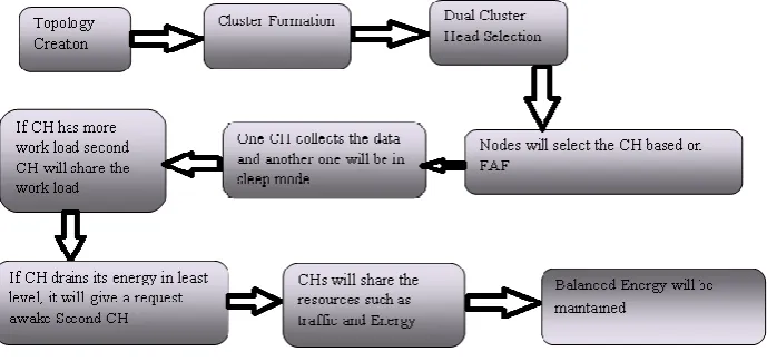
6. PROPOSED SYSTEM
To overcome the QOS loss, we proposed the Dual Cluster based resource sharing scheme.
Initially two Cluster Head are selected depending on the probability of cluster member
energy.
Also we includes FAF, here CH will elect by which node is placed forward direction to
the sink node.
Generally one cluster head will transfer the data to the base station and another one in
sleep mode operation carried. If it does more work means it will send awake message to
neighbor cluster to carry their operation.
Otherwise if it energy will be drain means its forward here energy to neighbor cluster to
do the operation. It will overcome the delay and packet loss in data transmission.
After a long time Dual Cluster cluster can drain means, it will select another pair of
clusters can chosen depends on members energy and these process will carried till all
Fig 6.1: Architecture Diagram.
6.1 Dual Clustering Algorithm
Here we use two clusters for data forwarding scheme.
It will be sleep mode in idle state and check the status periodically.
If cluster node had drain energy, it will send a request to the next CH node. That node can
begin to carry their information from neighbor.
Advantages
Does more work means, another cluster manage to work
If node failure occurs, immediately another cluster awake to carry the data
Delay and packet loss will be reduced
6.2 Algorithm Steps Cluster Formation
Cluster Head(CH) Selection
Cluster Head selects by the all the sensor nodes
All the nodes share their energy level to all the neighbors
All nodes check their energy into received energy level
If I have high energy
Yes, intimate all the nodes and share I am CH
No, waiting for the CH request
Cluster Members (CM) send the data to CH.
CMs observe the one hop neighbor activities.
Periodically it will forward to CA through CH
If the evidences are strong against the any sensor node
If yes means eliminate the node
If no continue the node as a CM.
Continue the Process.
6.3 Enhanced Forward Aware Factor–Energy Routing Methods
In this module we propose an Enhanced Forward Aware Factor-Energy Balanced Routing
Method (EFAF-EBRM) based on Data aggregation technique that has some key aspects such
as a reduced number of messages for setting up a routing tree, maximized number of
overlapping routes, high aggregation rate, and reliable data aggregation and transmission.
According to data transmission mechanism of WSN, we quantify the forward transmission
area, define forward energy density which constitutes forward-aware factor with link weight.
For energy efficient transmission in event-driven WSN, Data should be reduced. It requires
proper routing method for reliable transmission of aggregated data to sink from the source
nodes. This paper propose a new communication protocol based on forward-aware factor in
order to determine next-hop node and Data Routing for In-Network aggregation(DRINA)
protocol to reduce the number of transmissions and thus balancing the energy consumption,
prolonging the network function lifetime and to improve QoS of WSN.
The Routing Algorithm Can be Divided into Seven Stages as Follows
Determine and all of the possible next-hop nodes of node. First, take as the
communication radius, determine the set of all of the nodes that have edges with. Select
the nodes that closer to Sink than does, which constitute the set of all of the possible
next-hop nodes and the furthest node determine.
Determine and of each possible next-hop node. Determine as we determined. Plug the
furthest distance between and nodes in FTA and the distance between and Sink into and
obtain.
Calculate of each possible next-hop node. Plug all of the nodes’ energy into and get.
Calculate the weight of edges between and each nodes according to.
Plug the parameters of 3 and 4 and calculate FAF of each possible transmit link. Choose
If Sink is among the forward transmit nodes, will transmit data directly to Sink and
accomplish the procedure. In FAF-EBRM, the routing list structure of nodes. The
information of the table can guarantee all of the parameters FAF-EBRM algorithm
needed. The communication launch node can calculate the weight of edge between
neighbors. Neighbors can get its own FED. It avoids the communication launch node
doing all of the algorithms. Thus, each node’s memory should storage its own ID, real
time energy, distance to the Sink, and FED at any moment, which could be feed back to
launch node quickly.
7. HARDWARE AND SOFTWARE FEATURES 7.1 Motivation for Simulations
Cheap does not require costly equipment
Complex scenarios can be easily tested
Results can be quickly obtained
– More ideas can be tested in a smaller timeframe
The real thing isn't yet available
Controlled experimental conditions
– Repeatability helps aid debugging
Disadvantages: Real systems too complex to model
7.2 NS Features
NS is an object oriented discrete event simulator.
– Simulator maintains list of events and executes one event after another. – Single thread of control: no locking or race conditions.
Back end is C++ event scheduler – Protocols mostly
– Fast to run, more control.
Front end is OTCL
7.3 NS Programming Structure Create the event scheduler
Turn on tracing
Create network topology
Create transport connections
Generate traffic
Insert errors.
7.3.1 Event Scheduler
In this Event scheduler while we processing many data’s at a time it will process one by one
(i.e) FIFO concept, so there is no congestion while transfering the packets.
7.3.2 Packets
It is the collection of data, whether header is called or not all header files where present in the
stack registers.
Cmn header Ip header Tcp header Rtp header Trace header
7.3.3 Turn on Tracing
Trace packets on individual link Trace file format.
7.3.4 Create Network Topology (Physical Layer)
The Physical Layer is the first and lowest layer in the seven-layer OSI model of computer
networking. The implementation of this layer is often termed PHY.
The Physical Layer consists of the basic hardware transmission technologies of a network. It
is a fundamental layer underlying the logical data structures of the higher level functions in a
network. Due to the plethora of available hardware technologies with widely varying
characteristics, this is perhaps the most complex layer in the OSI architecture.
7.3.5 Transport Connection (Transport Layer)
Transport layers are contained in both the TCP/IP. Which is the foundation of the
INTERNET. And the OSI model of general networking. The definitions of the Transport
Layer are slightly different in these two models. This article primarily refers to the TCP/IP
model, in which TCP is largely for a convenient application programming interface to
internet hosts, as opposed to the osi model of definition interface.
The most well-known transport protocol is the (TCP). It lent its name to the title of the entire
internet protocol suite TCP/IP. It is used for connection-oriented transmissions, whereas the
connectionless user datagram suite(UDP) is used for simpler messaging transmissions. TCP
is the more complex protocol, due to its stateful design incorporating reliable transmission
and data stream services.
7.3.6. Generate Traffic (Application Layer)
In TCP/IP, the Application Layer contains all protocols and methods that fall into the realm
of process-to-process communications via an Internet Protocol (IP) network using the
Transport layer protocols to establish underlying host-to-host connections. In the OSI model,
the definition of its Application Layer is narrower in scope, explicitly distinguishing
additional functionality above the Transport Layer at two additional levels: session layer and
presentation layer OSI specifies strict modular separation of functionality at these layers and
provides protocol for each layer.
7.3.7 Insert Errors
Start debugging of errors.
7.4 Hardware Specifications
Main processor : Single pc
Hard disk capacity : 20 GB
Cache memory : 1 GB
7.5 Software Specifications
Operating system : Linux(ubuntu 10.04)
Scripting language : Network Simulator 2.34
Protocol developed : C++
7.6 Software Descriptions
7.6.1 Network Simulator 2.34 (NS2)
Network simulator (NS2) is a discrete event driven simulator developed at UC Berkeley. It is
part of the VINT project. The goal of NS2 is to support networking research and education. It
is suitable for designing new protocols, comparing different protocols and traffic
evaluations.NS2 is developed as a collaborative environment. It is distributed freely and open
source. A large amount of institutes and people in development and research use, maintain
and develop NS2.This increases the confidence in it.
Versions are available for Free BSD, Linux, Solaris, Windows and Mac OS X.NS2 is built
using object oriented methods in C++ and OTcl (Object Oriented variant of Tcl) in Figure 7.1
Fig.7.1: Simplified User’s View of Ns.
NS2 interprets the simulation scripts written in OTcl. A user has to set the different
components (e.g. event scheduler objects, network components libraries and setup module
libraries) up in the simulation environment. The user writes his simulation as a OTcl script,
plumbs the network components together to the complete simulation. If he needs new
network components,he is free to implement them and to set them up in his simulatiomn as
well. The event scheduler as the other major component besides netwok components triggers
the event of the simulation (e.g, sends packets, start and stop tracing ),some parts of NS2 are
written in the C++ for efficiency reasons. The data path (written in C++)is separated from the
control path (written in OTcl). Data path object are complied and then made available to the
Network simulator (NS) is an object-oriented, discrete event simulator for networking
research. NS provides substantial support for simulation of TCP, routing and multicast
protocols over wired and wireless networks. The simulator is a result of an ongoing effort of
research and developed. Even though there is a considerable confidencein NS, it is not a
polished product yet and bugs are being discovered and corrected continuously. NS is written
in C++,with an OTcl interpreter as a command and configuration interface. The C++ part,
which is fast to run but slower to change, is used for detailed protocol implementation. The
OTcl part on the other hand, which runs much slower but can be changed very fast quickly, is
used for simulation configuration. One of the advantages of this split-language program
approach is that it allows for fast generation of large scenarios. To simply use the simulator, it
is sufficient to know OTcl. On the other hand, one disadvantages is that modifying and
extending the simulator requires programming and debugging in both languages.
7.7 Implementation Environment
Network simulator 2 is used as the simulation tool in this project. NS was chosen as the
simulator partly because of the range of features it provides and partly because it has an open
source code that can be modified and extended. There are different versions of NS and the
latest version is ns-2.1b9a while ns-2.1b10 is under development NS can simulator the
following:
1. Topology : Wired, Wireless.
2. Scheduling Algorithm : RED, Drop Tail.
3. Transport protocols : TCP, UDP.
4. Routing : static and dynamic routing.
5. Application : FTP, HTTP, Telnet, Traffic generator.
7.8. User View of NS-2
7.9 Network Components
This section talks about the NS components, mostly compound network components.Fig.7.3
shows a partial OTcl class hierarchy of NS, which will help understanding the basic network
components.
Fig.7.3: OTcl clas Hierachy.
The root of the hierarchy is the Tcl Object class that is the super class of all OTcl library
object (schelduer, network components, timers and the other objects including NAM related
ones).As an ancestor clas of Tcl object, NS object class is the super class of all basic network
component objects that handle packets, which may compose compound objects such as node
and links. The basic network components are further divided into two subclasses, connector
and classifier, based on the number of the possible output DATA paths. The basic network
and objects that have only one output DATA path are under the connector class, and
switching objects that have possible multiple output DATA paths are under the classifier
class.
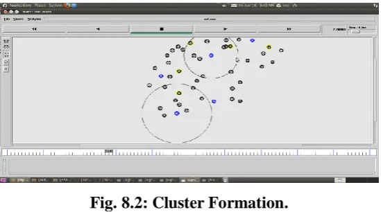
Fig. 8.2: Cluster Formation.
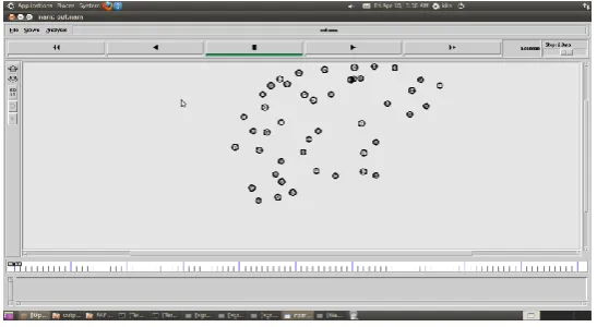
Fig.8.1,Shows that all nodes are deployed uniformly and there are totally 49 nodes
Fig.8.2,Nodes are represented in different colors.Each color Shows various Cluster.
Fig. 8.3: Data Tranamission.
Fig. 8.4: Second CH in Active Mode.
Fig.8.3, The collected data from every nodes is sent to the Cluster Head (CH) and the CH
aggregates the data and transmits to the Sink.
Fig.8.4, One cluster node had drain energy, it will send a request to the next CH node. That
Fig.4.2 illustrates comparision of packet delay rate. Here introducing time delay between
packets, we are reducing packet loss. So that the transmitted no.of packets will be increased
from 16952 to 17600.So that, in proposed system packet delivery ratio is high.
Fig.4.2 illustrates Energy comparision of both existing and proposing system. Here the
energy saving is achieved from 62.12 to 75.12.This is because in proposed system, if one CH
drains its energy another CH will share the resources such as traffic and energy. Hence
CONCLUSION
This paper proposes a Dual clustering algorithm extended from Energy-efficient and Load-
balancing Cluster-based (ELC) routing algorithm for CSMA-based WSNs. Dual clustering
algorithm takes into consideration both distance and residual energy in the CH selection. In
addition, Dual clustering algorithm balances the load and energy consumption among CHs by
employing the number of members in cluster forming and in the multi-hop inter-cluster
communication. The simulation results show that Dual cluster algorithm can reduce the total
energy dissipation and extend network lifetime while sustaining the performance in terms of
the amount of data delivered to the BS.
REFERENCE
1. Akhtar et. al. has presented - Energy Aware Intra Cluster Routing for Wireless sensor
networks, in 2010.
2. Zijian Wang et. al. has presented-Energy Efficient Collision Aware Multipath Routing for
Wireless sensor networks, in 2009.
3. Ming Liu et. al. has presented An Energy-Aware Routing Protocol in Wireless sensor
networks, in 2009.
4. Lu Su et. al. has presented Routing in Intermittently Connected sensor networks, in 2009.
5. K. Akkaya et. al. has presented A survey on routing protocols for wireless sensor
networks, in 2005.
6. Basil Etefia et. al. has presented Routing Protocols for Wireless sensor networks, in
Berkeley Information. Technology (SUPERB–IT) 2004.
7. A.P.Subramanian et. al. has presented Multipath Power Sensitive Routing Protocol for
Mobile Ad hoc Networks in 2004.
8. Charles E.Perkins et. al. has presented Ad-hoc On- Demand Distance Vector Routing in
2003.
9. Fan Ye et. al. has presented A Two-Tier Data Dissemination Model for Large-scale
Wireless sensor networks, in 2002.
10.Maurice Chu et. al. has presented Scalable Information-Driven sensor Querying and
Routing for ad hoc Heterogeneous sensor networks, in 2002.
11.Sameer Tilak et. al. has presented “A Taxonomy of Wireless Micro-sensor Network
Models, in 2002.
13.M. Younis et. al. has presented Energy-Aware Routing in Cluster-Based sensor networks,
in 2002.
14.Schurgers et. al. has presened Energy Efficient Routing in Wireless sensor networks, in
2002.
15.Curt Schurgers et. al. has presented Energy Efficient Routing in Wireless sensor