Design and Simulation of PI Controller for Double
Output Luo Converter
R.Subbulakshmy
Assistant Professor, Department of Electrical And Electronics, Panimalar Institute of Technology, Chennai, Tamil Nadu, India
Abstract—Mirror-symmetrical double-output voltages are specially required in industrial applications and computer periphery circuits. Double output DC-DC converters can convert the positive input source voltage to positive and negative output voltages by two conversion paths. Because of the effect of parasitic elements, the output voltage and power-transfer efficiency of DC-DC converters are limited. The voltage-lift technique is a popular method that is widely applied in electronic circuit design. This technique gives a good way of improving circuit characteristics, and has been successfully applied for DC-DC converters. As are single output (positive and negative output) Luo converters, double-output Luo converters are a series of new DC-DC step-up converters using only one switch. They are developed from advanced voltage-lift technique. These converters perform from positive to positive and negative DC-DC voltage-increase conversion with high power density, high efficiency and cheap topology in a simple structure. They are different from any other existing DC-DC step-up converters and possess many advantages including high output voltage with small ripples. Therefore these converters will be widely used in computer peripheral equipment and industrial applications, especially for high double-output voltage projects. The present work is to design the Double Output Luo Converter and their operation is monitored and controlled by using PI control techniques. MATLAB software is used to study the dynamic characteristics and analyze the closed loop performances of these converters with resistive load under supply and load disturbances. The simulation results closely matches with each other and highlights the validity of the developed control scheme. Key words—PI, Positive conversion path and Negative conversion path.
I.INTRODUCTION
Double-output DC-DC converters can convert the positive input source voltage to positive and negative output voltages. They consist of two conversion paths. Usually, mirror symmetrical double-output voltagesare especially required in industrial applications and computer periphery circuits such as operational amplifiers, computer periphery power supplies, differential servomotor drives and some symmetrical-voltage medical equipment. In recent years, the DC-DC conversion technique has been greatly developed. Because of the effect of parasitic elements, the output voltage and power transfer efficiency of all DC-DC converters is restricted. The voltage-lift technique is a popular method that is widely applied in electronic circuit design. It can open a good way of improving DC-DC converters‘ characteristics; and has been successfully applied for DC-DC converters. As are the positive and negative output Luo converters [1-8], double-output Luo converters are a series or new DC-DC step-up (boost) converters, which were developed by using the
advanced voltage- lift technique. Only one switch S is employed to control dual mirror-symmetrical output voltages. These converters perform from positive to positive and negative DC-DC voltage -increase conversion with high power density, high efficiency and cheap topology in a simple structure, these converters are different from any other existing DC-DC step-up converters and possess many advantages, including a high output voltage with small ripples.
II.DOUBLE OUTPUT LUO CONVERTER
The re-lift circuit shown in Fig.1 is derived from the self-lift circuit. The positive conversion path consists of a pump circuit S-Ll-Do-C1 and a filter (C2)-L2-C0, and a lift circuit D1-C2-D3-L3-D2-C3.The negative conversion path consists of a pump circuit S-L11-D10-(C11) and a -type filter C11-L12-C10, and a lift circuit D11-C12-L13-D22-C13- D12.
Fig. 1 Re-lift circuit
A. POSITIVE CONVERSION PATH:
switching-on, and - (VC1-V1,) during switching-off. We have the relations
Thus
The voltage-transfer gain in the continuous mode is
(a)
(b)
(c)
Fig.2 Equivalent circuit of positive conversion path. a. S : ON; D: OFF
b. S: OFF; D: ON c. Discontinuous mode.
B. NEGATIVE CONVERSION PATH:
The equivalent circuit during switch on is shown in Fig. 3 the equivalent circuit during switch ON is shown in Fig. 3a and the equivalent circuit during switch OFF is shown in Fig.
and
The voltage-transfer gain in the continuous mode is defined by
Circuit (C11-L12-C10) is a ‗π‘-type low-pass filter. Therefore
(a)
(b)
(c)
Fig.3 Equivalent circuit of negative conversion path. a. S: ON; D: OFF.
b. S: OFF;D: ON c. Discontinuous mode.
simple and based on three basic behavior types or modes: proportional (P), integrative (I) and derivative (D). Instead of using a small number of complex controllers, a larger number of simple PID controllers are used to control complex processes in an industrial assembly in order to automate the certain more complex process. Controllers of different types such as P, PI and PD are today basic building blocks in control of various processes. In spite of simplicity, they can be used to solve even a very complex control problem, especially when combined with different functional blocks, filters (compensators or correction blocks), selectors etc. A continuous development of new control algorithms insure that the PID controller has not become obsolete and that this basic control algorithm will have its part to play in process control in foreseeable future. It can be expected that it will be a backbone of many complex control systems. While
proportional and integrative modes are also used as single control modes, a derivative mode is rarely used in control systems. PI controller forms the control signal in the following way:
Using the transfer function, the tuning of the controller is done by the reaction curve method. Controller tuning involves the selection of the best values of Kp and Ti.
IV.SIMULATIONRESULTS
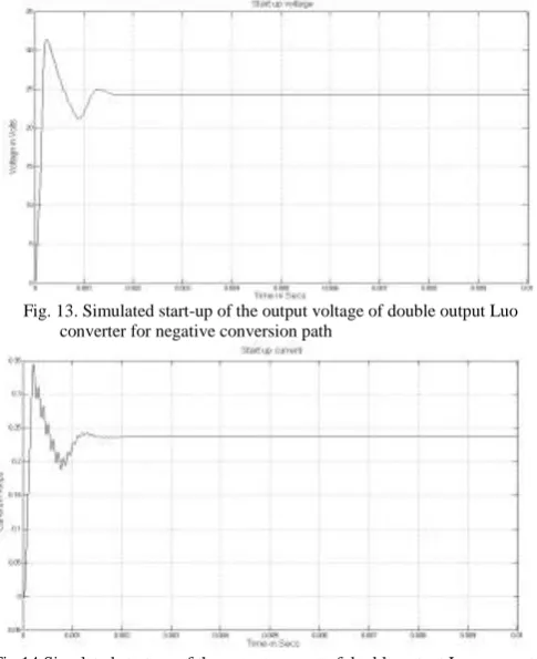
Fig.4 shows the startup voltage of double output Luo converter with PI controller for totol output voltage. Fig 5 shows the line disturbance voltage of double output Luo converterWith PI controller and 10% linedisturbances for totol output voltageFig.6 show the output current of double output Luo converter with PI controller and 10% loaddisturbances for totol output voltage. Figs.7 and 8 shows the startup voltage and current of double output Luo converter with PI controller for positive conversion path. Figs.9 and 10 show the output voltage and current with PI controller of 10% line disturbances for positive conversion path Figs.11 and 12 show the output voltage and current with PI controller of 10% load disturbances for positive conversion path. Figs.13 and 14 shows the startup voltage and current of double output Luo converter with PI controller for positive conversion path. Figs.15 and 16 shows the output voltage and current with PI controller of 10% line disturbances for negative conversion path Figs.17 and 18 shows the output voltage and current with PI controller of 10% load disturbances for negative conversion path.Table I shows the performance evaluation of PI controller for double output Luo converter with resistive load using MATLAB.
Fig. 4 Simulated start-up of the output voltage of double output Luo converter for totol output voltage.
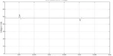
Fig. 5 Simulated output voltage of double output Luo converter with sudden line disturbances 12-15-12 volts for totol output voltage
Fig. 6 Simulated output current of double output Luo converterwith sudden load disturbances under nominal load (100Ω –90Ω -100Ω) for total output voltage.
Fig. 8Simulated start-up of the output current of double output Luo Converter for positive conversion path
Fig. 9 Simulated output voltage of double output Luo Converter with sudden line disturbances 12V-15V-12V for positive conversion path.
Fig. 10. Simulated output Current of double output Luo converterwith sudden line disturbances 12V-15V-12V for positive conversion path.
Fig. 12 Simulated output current of double output Luo converterwith sudden load disturbances under nominal load (100Ω –90Ω -100Ω) for positive conversion path.
Fig. 13. Simulated start-up of the output voltage of double output Luo converter for negative conversion path
Fig. 16 Simulated output current of double output Luo converterwith sudden load disturbances under nominal load (100Ω –90Ω -100Ω)for negative conversion path.
Figure 17. Simulated output voltage of double output Luo converterwith sudden load disturbances under nominal load (100Ω –90Ω -100Ω)for negative conversion path.
Fig. 18 Simulated output current of double output Luo converterwith sudden load disturbances under nominal load (100Ω –90Ω -100Ω)for negative conversion path.
V. CONCLUSION
The Simulation results show that the proposed PI controller regulates satisfactorily the output voltage of Double-output Luo converters irrespective of line and load disturbances. It also overcomes the effects of parasitic elements and greatly increases the output voltage of the DC-DC converters, introducing the characteristics of high efficiency, high power density, and cheap topology and near-zero output voltage and current ripples. Carefully selecting the parameters, we can obtain mirror-symmetrical double-output voltages from a positive input source. These converters can be used in computer periphery circuits, medical equipment and industrial applications with high output voltages.
REFERENCES
[1] Luo F. L. ―Positive Output Luo-Converters: Voltage Lift Technique‖ IEE-EPA Proceedings Vol. 146, No.4, July 1999, p
415-432.
[2] Luo F. L. ―Negative Output Luo-Converters: Voltage Lift Technique‖ IEE-EPA Proceedings Vol. 146, No.2, March 1999, pp. 208-224.
[3] Luo F. L. ―Re-Lift Converters: Design, Test, Simulation and Stability Analysis‖ IEE-EPA Proceedings Vol. 145, No.4, July 1998, pp. 315-325.
[4] Luo F. L. ―Double Output Luo-Converters‖ Proceedings of the IEEE International conference IPEC‘99, Singapore, 24-26 May 1999, pp. 647- 652.
[5] Luo F. L. and Ye H. ―Switched Inductor Two-Quadrant DC/DC Converter with Fuzzy Logic Control‖ Proceedings of the IEEE International conference PEDS‘99, Hong Kong, 26-29 July 1999, pp. 773-778.
[6] Luo F. L. and Ye H. ―Switched Inductor Two-Quadrant DC/DC Converter with Neural Network Control‖ Proceedings of the IEEE International conference PEDS‘99, Hong Kong, 26-29 July 1999, pp. 1114-1119.
[7] Smedley K. M. and Cuk S. ―Dynamics of One-Cycle controlled Cuk
Converter‖ IEEE transactions on PE, Vol. 10, No. 6, November 1995, pp.634-639.
[8] Kassakian J. G., Wolf. H., Miller. J. M. and Hurton. C. J.Automotive Electrical systems circa 2005‖ IEEE Spectrum, August 1996, pp. 22-27 [9] Ye, F. L. Luo, and Z. Z. Ye, ―High-efficiency, widely-adjustable high
voltage regulated power supply,‖ in Proc. Int. IPEC‘99 Conf., Singapore, 1995.
[10] F. L. Luo, H. Ye, and M. H. Rashid, ―Four-quadrant operating Luo Converters,‖ in Proc. IEEE Int. PESC‘00 Conf., Galway, Ireland, June18–23, 2000, pp. 1047–1052.
TABLE I . PERFORMANCE EVALUATION OF PI CONTROLLER FOR DOUBLE OUTPUT LUO CONVERTER WITH RESISTIVE LOAD USING MATLAB
Startup Transient Line Disturbance Load disturbance
CONVERSION PATHS Delay time (msecs) Rise time (msecs) Peak over shoot (% ) Peak time (msecs) Settling time (msecs) Supply increase 10% Supply decrease 10% Load increase 10% Load decrease 10% Peak over shoot (% ) Settling time (msecs) Peak over shoot (% ) Settling time (msecs) Peak over shoot (% ) Settling time (msecs) Peak over shoot (% ) Settling time (msecs) TOTAL OUTPUT
9.55 0.74 36.58 0.22 0.12 9.85 0.01 7.35 0.04 .39 53.2 .41 75.8