ISSN (Online): 2320-9364, ISSN (Print): 2320-9356
www.ijres.org Volume 3 Issue 8 ǁ August. 2015 ǁ PP.48-56
Determination of Buckling Loads of Wave Spring Using ANSYS
Dr P. Ravinder Reddy
1, V. Mukesh Reddy
21Professor & Head, Dept. of Mech. Engg. Chaitanya Bharathi Institute of Technology, Hyderabad, TS, India. 2PG student, Dept. of Mech. Engg. CBIT, TS, India
Abstract:- Special performance characteristics are individually built into each spring to satisfy a variety of precise operating conditions. Typically, a wave spring will occupy an externally small area for the amount of work it performs. The present work deals with the structural analysis of wave and coil spring by modeling the structural behavior of these springs using three dimensional finite elements (FE) software. The design of spring in suspension system is very important. In this work a wave type of spring is designed and a 3D model is created using CREO software. The model is also varied by changing the length of the spring. Structural analysis has been conducted on the wave spring by varying thickness and number of turns. For the analysis, loads are bike weight with single and two persons. The buckling load is then estimated for both Wave spring and coil spring with the same parameters.
Keywords: - Coil spring, Wave spring, Buckling factors, Natural frequency, Fatigue life
I.
Introduction
Springs are flexible machine elements used for controlled application of force (or torque) or for storing and release of mechanical energy. Simple non-coiled springs were used throughout human history, e.g. the bow (and arrow).In the Bronze age more sophisticated spring devices were used, as shown by the spread of tweezers in many cultures. Alexandria developed a method for making bronze with spring-like characteristics by producing an alloy of bronze with an increased proportion of tin, and then hardening it by hammering after it was cast. Coiled springs appeared early in the 15th century, in door locks. The first spring powered-clocks appeared in that century and evolved into the first large watches by the 16th century. Rajkumar V. Patil et all[1-2] studied buckling behavior of coil springs with experimental and numerical investigations. James M. Meagher et al[3]; r presented the theoretical model for predicting stress from bending agreed with the stiffness and finite element model within the precision of convergence for the finite element analysis. M. T. Todinov [4] , given for helical compression spring with a large coil radius to wire radius ratio, the most highly stressed region was at the outer surface of the helix rather than inside. The fatigue crack origin was located on the outer surface of the helix where the maximum amplitude of range of the maximum principal tensile stress. Kotaro Watanabe[5], a new type rectangular wire helical spring was contrived by the authors was used as suspension springs for rally cars, the stress was checked by FEM analysis theory on the twisting part. Dammak Fakhreddine et al [6],in this paper the author presented an efficient two nodes finite element with six degrees of freedom per node, capable to model the totalbehavior of a helical spring. The working on this spring was subjected to different cases of static and dynamic loads.C. Berger, B. Kaiser [7] presented the first results of very high cycle fatigue tests on helical compression springs. The springs tested were manufactured of Si–Cr-alloyed valve spring wire with a wire diameter between 2mm and 5 mm, shot-peened and the fatigue tests were continued up to 108cycles or even more. L. Del Llano-Vizcaya et al[8] given an experimental investigation been conducted to assess the stress relief influence on helical spring fatigue properties. First S–N curves were determined for springs treated under different conditions (times and temperatures) on a testing machine.
al[13], it was found that the existing primary suspensions with composite spring assembly could sustain loads in normal operating conditions and maintain the required ride index, however, during cornering and hunting speeds failure of outer spring of primary suspension was observed. Kushal A Jolapara[14] showcase that there was a clear difference between the two cases of spring loading under static conditions. The load, load rates and stress values were higher for restricted uncoiling springs compared to unrestricted uncoiling. Tausif M. Mulla [15],the elastic behavior and the stress analysis of springs used in the Three Wheeler Vehicle‟s front automotive suspension was discussed in this paper. The results obtained by a fully 3D FE analysis also highlighted the poor accuracy that can be provided by the classical spring model when dealing with these spring geometries.
D.V Dodiya et al.[16], in this work attempt was made to analyze a leading arm in a horizontally oriented spring damper assembly and the geometric and space and force requirements were studied to improve road handling abilities. B. Ravi kumar et al [17] was analysed the failure of a helical compression spring employed in coke oven batteries surface corrosion product was analyzed by X-ray diffraction (XRD) and scanning electron microscope - energy dispersive spectroscopy (SEM–EDS). Reza Mirzaeifar, Reginald DesRoches, Arash Yavari [18], the pseudo elastic response of shape memory alloy (SMA) helical springs under axial force is studied both analytically and numerically. In the analytical solution two different approximations are considered. Niels stergaarda, Anders Lyckegaard, Jens H. Andreasen [19] work presented in this paper is motivated by a specific failure mode known as lateral wire buckling occurring in the tensile armor layers of flexible pipes. Tamas Varady [20] et al proposed the reverse engineering of complex shapes. Firstly they discussed different data acquisition techniques like in optical methods triangulation, ranging, interferometry, structured lighting and image analysis all in order to locate a surface point relative to a reference plane in order to measure the geometry of model.
II.
Analysis of coil and wave spring
2.1 Stability of the spring (Buckling):Buckling of column is a familiar phenomenon. Compression coil springs will buckle when the free length of the spring is larger and the end conditions are not proper to evenly distribute the load all along the circumference of the coil. The coil compression springs will have a tendency to buckle when the deflection (for
agiven free length) becomes too large. Buckling can be prevented by limiting the deflection of the spring or the free length of the spring. The behavior can be characterized by using two dimensions less parameters, critical length and critical deflection. Critical deflection can be defined as the ratio of deflection (y) to the free length (Lf) of the spring. The critical length is the ratio of free length (Lf) to mean coil diameter (D).The critical deflection is a function of critical length and has to be below a certain limit. For reducing the buckling effect following condition must be satisfied as Lf< 4D and the crippling load can be given by Wcr=K x KB x Lf where, K=spring rate and KB=buckling factor.
2.2 Spring surge and critical frequency:
If one end of a compression spring is held against a flat surface and the other end is disturbed, a
compression wave is created that travels back and forth from one end to the other exactly like the swimming pool wave. Under certain conditions, a resonance may occur resulting in a very violent motion, with the spring actually jumping out of contact with the end plates, often resulting in damaging stresses. This is quite true if the internal damping of the spring material is quite low. This phenomenon is called spring surge or merely surging. When helical springs are used in applications requiring a rapid reciprocating motion, the designer must be certain that the physical dimensions of the spring are not such as to create a natural vibratory frequency close to the frequency of the applied force. Traditionally the springs are made up of materials. The main factor is to be considered in design of spring is the strain energy of material used. Strain energy in materials can be expressed as U = f2/ (g). This indicates that the material with lower young's modulus (E) or density (ρ) will have relatively higher strain energy under same stress (f)
2.3 Spring relaxation:
Springs of all types are expected to operate over long periods of time without significant changes in dimension, displacement, or spring rates, often under fluctuating loads. If a spring is deflected under full load and the stresses induced exceed the yield strength of the material, the resulting permanent deformation may prevent the spring from providing the required force or to deliver stored energy for subsequent operations.
III.
Methodology
3.1 Stresses in wave spring:Operating stress, S=3ПPDm/4bt2
3.2 Deflection:
δ= (PKDmZ) ID/ (Ebt3N4 OD), Where K=multiple wave factor, Z=number of turns, N= number of waves per turn, ID and OD are inside and outside diameters, Multiple wave factor (K)
3.3 Springs specifications:
The parameters describes spring specification of coil and wave spring. Coil spring: Mean Diameter (Dm): 60mm, Coil Diameter (d): 12 mm, Number of turns (n): 10, Pitch (p): 24mm, Free length (Lf): 300mm Wave spring : Mean Diameter (Dm): 60mm, Free length (Lf): 300mm, Number of turns (Z):10, Thickness (t): 0.54mm, Number of waves per turn (N): 2, Width of wave (b): 0.5
3.4. Theoretical calculations: Material: Structural steel, Properties: Young‟s modulus (E) = 2×10⁵ MPa,
Density of material (ρ) = 7850 kg/m3
,Poisson‟s ratio (µ) = 0.3, Shear modulus (G) = 0.769× 10⁵, Yield strength = 300 MPa, Coil spring: Deflection (δ) = 8 WD3n/Gd4= 8 (1000×603×10)/ (0.769×100000) =
10.85mm
Spring stiffness (k) = (W/δ)= 1000/10.85= 92.16 N/mm. Wave spring: Deflection(δ) =(PKDmZ)ID/(Ebt3N4 OD)= (1000×3.88×60×47)/ (2×100000×0.5× (0.54)3× 24 × 54)= 8.01mm, Spring stiffness (k) = W/δ= 1000/8.01= 124.25 N/mm
IV.
Modeling of the spring:
Modeling of the coil spring and wave spring is done using CREO modeling software. Coil spring model: Mean diameter: 60mm; Free Length: 300mm; pitch: 24mm, Wire diameter (d):12mm; number of turns: 10, WAVE SPRING: Outer diameter: 54mm; I.D:47mm; free length: 300mm ,Number of waves per turn: 2; number of turns: 10, Thickness: 0.54mm
V.
Results and discussions:
Structural analysis coil spring:
a. Deformation, mm b.Equivalent stress, MPa Figure1: Deformation and equivalent stress of coil spring when load is 1000N.
a. Deformation, mm b. Equivalent stress, MPa Figure2: Deformation and equivalent stress of coil spring when load is 1200N
Figure3: Variation of deformation with increasing load of coil and wave spring
Figure4: Variation of strain energy with increasing load of coil and wave spring
From Fig.4 it is observed that as load increases strain energy increases and the strain energy of wave spring is less than coil spring. The average percentage variation is 21.3%.
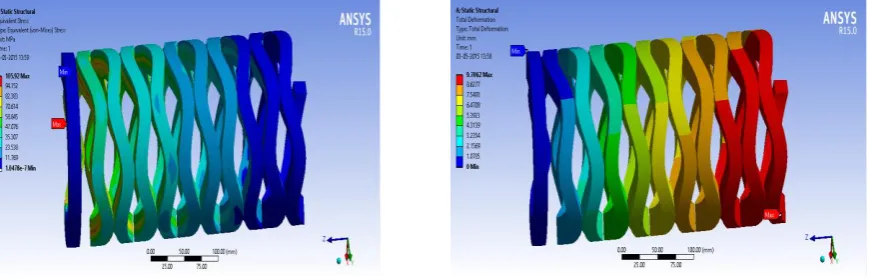
Analysis of coil and wave spring: The Fig.5 show deformations and equivalent stress of coil spring when number of turns is 8 and load is 1200N. From this analysis when number of turns increases, compared to coil spring wave spring has less deformation. The Fig.6, and 7 shows deformations and equivalent stress of Wave spring when free length is 300 mm and load is 1200N. From this analysis compared to coil spring wave spring has less deformation.
a.Deformation, mm b. Equivalent stress, MPa
Figure5 Deformation and equivalent stress of coil spring when number of turns=8
5.1. Comparison of coil and wave spring when No. of turns varying
a. Deformation, mm b. Equivalent stress, MPa Figure6: Deformation and equivalent stress of wave spring when number of turns=8
a. Deformation, mm b. Equivalent stress, MPa Figure7: Deformation and equivalent stress of wave spring when number of turns =10
Table 1: Variation of deformation and stress of coil and wave spring
No. of turns
Coil spring Wave spring
Deformation(mm) Equivalent stress, MPa Deformation(mm) Equivalent stress, MPa
8 9.08 330 8.80 130.45
10 9.97 340 9.81 138.89
12 11.45 350 10.91 142.55
14 13.01 370 12.85 151.45
5.2 Comparison of coil and wave spring when free length varying
The Fig.8 shows variation of deformations when free length changes by keeping number of turns constant. By comparison for less number of turns coil spring is better than wave spring. From Table2 it is found that for 300mm free length wave spring is having less deformation, but for 250mm length coil spring gives less deformation.
a. Coil spring b. Wave spring Figure8: Deformation of coil and wave springs when free length is 300mm
Table2: Variation of deformation of coil and wave spring with free length Deformation in mm
Free length in mm Coil spring Wave spring
300 9.08 8.85
250 8.34 8.63
5.3 Analysis of coil and wave spring (Twisting moment acting alone)
When a spring is subjected to twisting moment shear stress is developed and also strain energy is stored. Fig.9, and 10 shows variation of shear stress with twisting moment, and strain energy. The Shear stress in Coil spring is given by, τ = 8WD/Πd3
, then the Strain energy developed is given by, U=32T2Dn/Ed4
a.Coil spring b. Wave spring Figure9: Variation of shear stress with twisting moment
a. Coil spring b. Wave spring Figure10: Variation of strain energy with twisting moment
5.4 Comparison of Coil and Wave spring when twisting moment varying
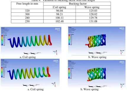
When a spring is subjected to twisting moment shear stress is developed and also strain energy is stored. From Table3 as twisting moment increases shear stress also increases. From Table3, it is observed that as twisting moment increases shear stresses of both springs‟ increases but as compared to coil spring there is lot of deviation in shear stress for same parameters. Since in applications where twisting moment acting wave spring gives better results compared to coil spring. It is also observed that equivalent stress for coil spring is high compared to wave spring therefore coil spring fails easily. From results, as twisting moment increases strain energy increases. The strain energy variation with twisting moment is observed that Wave spring possess more elastic strain energy compared to coil spring.
Table 3: Variation of shear stress, equivalent stress and strain energy with torque
Twisting Moment, N-m
Coil spring Wave spring
Shear Stress (MPa)
Equivalent Stress (MPa)
Strain Energy (MJ)
Shear Stress (MPa)
Equivalent Stress (MPa)
Strain Energy (MJ)
130 118.43 230.71 6.40 48.11 94.15 20.59
150 130.28 253.78 7.73 58.52 108.65 27.41
180 148.24 288.39 9.99 69.61 130.38 38.48
200 165.81 323.01 12.53 81.02 145.02 45.42
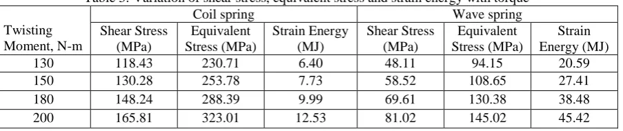
5.5 Linear buckling analysis
The results show, there is lot of deviation in buckling factor of wave spring. The Fig.11shows buckling of springs
a. Coil spring b. Wave spring Figure11: Buckling of coil and wave spring when free length =300mm
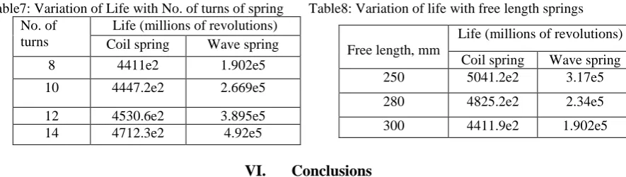
The Table4 shows variations of buckling load with free length of both coil and wave spring. Buckling factor is higher for wave spring in comparison. As free length increases buckling factor decreases. The buckling factor for coil spring is an average 26 % less compared to wave spring.
5.6 Modal analysis
The mode shapes are given in Fig.12. Modal analysis gives natural frequencies of both Coil and Wave spring in different modes. Natural frequency for springs is given by
The natural frequency equations are for springs fixed at both ends. If only one end of the spring is fixed, it behaves like a fixed-fixed spring of twice its length. Thus, for a spring with only one end fixed, the frequency is 1/2 the value given by the above equations. The Table5 gives natural frequencies for different springs of coil and wave. Wave spring has less natural frequency for different modes. At mode 5 the natural frequency of coil spring is 79 Hz whereas wave spring has 38Hz; hence it is observed that the natural frequency in wave spring is average 44.24% less than coil spring.
Table 4: Variation of buckling factor with free length Free length in mm Bucking factor
Coil spring Wave spring
320 96.04 125.03
300 98.21 128.02
280 100.11 129.78
250 102.48 131.08
a. Coil spring b. Wave spring
Table 5: Variation of natural frequencies for different modes
Natural frequency is indirectly proportional to number of turn‟s .As number of turn‟s increases natural frequency decreases so that vibrations are more. Table6 gives variation in frequency with number of turns. From comparison coil spring has less vibration effect than wave spring since wave spring has less natural frequency compared to coil spring. Since for higher number of turns coil spring has a natural frequency of 40.05 Hz and wave spring has 21.88 Hz.
Table6: Variation of frequency with No. of turns
5.7 Fatigue analysis
The main factors that contribute to fatigue failures include number of load cycles experienced, range of stress and mean stress experienced in each load cycle and presence of local stress concentrations. IC engine valve spring and automobile horn are subjected to high fatigue loads. In fatigue analysis I vary number of turns and free length of both coil and wave spring and results are tabulated. Life of spring varies with number of turns. The Ttable7 gives minimum number of cycles required. From results it is observed that as number of turn‟s increases minimum life to failure increases, but wave spring has minimum life of 3.89e5 compared to coil spring of life 4530.6e2, therefore wave spring give more life. The Table8 gives minimum number of cycles required. From results it is observed that as free length increases minimum life to failure decreases, but wave spring has high fatigue life compared to coil spring.
Table7: Variation of Life with No. of turns of spring Table8: Variation of life with free length springs No. of
turns
Life (millions of revolutions) Coil spring Wave spring
8 4411e2 1.902e5
10 4447.2e2 2.669e5
12 4530.6e2 3.895e5 14 4712.3e2 4.92e5
VI.
Conclusions
Analysis on wave spring has been done by structural mechanics approach and results were validated and compared with the coil spring of the shock absorber. The deflection induced in the wave spring is average 25.88% less than the coil spring. The equivalent stress of wave spring is an average 58.32% less than coil spring. The strain energy of wave spring is an average 21.3% greater than coil spring. For less number of turns and free length Wave spring has a deformation of 8.63 whereas coil spring has 8.34, so if we use 8 number of turns and free length of 250mm coil spring is best suitable but as we increase free length or number of turns wave spring is better. The strain energy increases with increase in torque and it is an average 60% greater in wave spring compared to coil spring. From Buckling analysis buckling factor decreases with increase free length. The buckling factor in wave spring is an average 26% greater than coil spring. From Modal analysis coil spring produces less vibration effect about an average 44.24% compared to wave spring. As number of turns increases natural frequency decreases, coil spring has an average 52.55% less vibrations compared to wave spring. By performing Fatigue analysis, wave spring has high fatigue life is an average 15 % compared to coil
Mode No
Natural frequency, Hz
Coil spring Wave spring % Variation
1 14.24 8.45 40.66
2 14.40 8.55 40.63
3 24.98 15.98 36.12
4 43.09 23.21 46.13
5 79.03 35.01 59.12
No. of turns
Natural frequency, Hz
Coil spring Wave spring
8 79.03 35.89
10 65.72 31.52
12 56.18 27.89
14 40.05 21.88
Free length, mm
Life (millions of revolutions)
Coil spring Wave spring 250 5041.2e2 3.17e5
280 4825.2e2 2.34e5
spring. As free length increases fatigue life decreases and wave spring is better life compared to coil spring about 30%.
References:
[1] Rajkumar V. Patil; Dr. P. Ravinder Reddy; Dr. P. Laxminarayana, Buckling Analysis of Straight Helical Compression Springs Made Of ASTMA229 Gr-II, ASTM A 313 Materials (Type 304 & 316). International journal of engineering research & technology (IJERT), Vol.2. Issue 6, June-2013.
[2] Rajkumar V.Patil, P. Ravinder Reddy and P. Laxminarayana, „Comparison of cylindrical and conical helical springs for their buckling load and deflection‟, International Journal of Advanced Science and technology, vol.73 ,pp-33-50, 2014, http://dx.doi.org/10.14257/ijast.2014.73.03.This journal is from Science and Engineering Research Support Society , KOREA. [3] James M. Meagher and Peter Altman (1996), “Stresses from flexure in composite helical implantable leads”.
[4] M.T. Todinov (1999), “Maximum principal tensile stress and fatigue crack origin for compression springs, international journal of mechanical sciences”, vol. 41, pp. 357-370.
[5] Watanabe Kotaro, Tamura Masashi, Yamaya Ken &Takahiko Kunoh (2001), “Development of a new-type suspension spring for rally cars”, Journal of materials processing technology, pp. 132-134.
[6] Fakhreddine Dammak, Mohamed Taktak, Said Abid, Abderrazek Dhieb & Mohamed Haddar (2005), “Finite element method for the stress analysis of isotropic cylindrical helical spring”, journal of mechanics and solids, vol.24, pp. 1068-1078.
[7] C. Berger & B. Kaiser (2006), “Results of very high cycle fatigue tests on helical compression springs”, international journal of fatigue, vol. 28, pp. 1658-1663.
[8] L. Del Llano-Vizcaya, C. Rubio-Gonzalez & G. Mesmacque (2007), “Stress relief effect on fatigue and relaxation of compression springs”, material and design, vol.28, pp.1130-1134.
[9] Y. Prawoto, M. Ikeda, S.K. Manville & A. Nishikawa (2008), “Design and failure modes of automotive suspension springs”, engineering failure analysis, vol.15, pp. 1155–1174.
[10] Hsin-Tsun Hsu, Christopher Coker and Hubert Huang (2010), “Optimization of an electric vehicle suspension system using CAE”, world electric vehicle journal, vol. 4, pp. 179-183.
[11] Mehdi Bakhshesh and Majid Bakhshesh (2012), “Optimization of steel helical spring by composite spring”, international journal of multidisciplinary science and engineering, vol.3, issue- 6, pp.222-232.
[12] Brita Pyttel, K K Ray, Isabell Brunner, Abhishek Tiwari, S. A. Kaoua, IOSR Journal of Mechanical and Civil Engineering (IOSRJMCE) ISSN :2278-1684 Volume 2, Issue 3 (Sep-Oct. 2012).
[13] Priyanka Ghate, “Failure Investigation of a Freight Locomotive Suspension Spring and Redesign of Spring for Durability and Rideindex” sasTECH. Volume 11, issue 2, Sep 2012.
[14] Kushal A Jolapara, “Study of Uncoiling in Suspension Spring its Effects” International journal of advance research & studies, volume 12. Issue 3, Sep 2012.
[15] Tausif M Mulla, “Finite Element Analysis of helical coil spring for three wheeler automotive front suspension,” international journal of Mechanical and Production Engineering, volume 1, issue 1, 2012, pp.164-169.
[16] D.V Dodiya, “Static Analysis of Leadingarm in Suspension system with Horizontal Shockabsorbers” volume 4, issue 2, 2012, pp. 1-2.
[17] B. Ravi Kumar, Swapan K. Das, & D.K. Bhattacharya (2003), “Fatigue failure of helical compression spring in coke oven batteries”, engineering failure analysis, vol. 10.pp. 291–296.
[18] Reza Mirzaeifar, Reginald DesRoches, Arash Yavari, “A Combined Analytical, Numerical and Experimental study of Shape memory- alloy helical spring” International journal of Solid Structure, volume 2, issue 1, 2011, pp.611-624.
[19] Niels stergaarda, Anders Lyckegaard, Jens H. Andreson, “CAE Analysis for Fatigue Failure for Coiled spring life Enhancement in Press Machine Stamping Operation” IJAER, volume 3, issue 3, June 2014, pp. 61-63.