A Vehicle Map-matching Algorithm based on
Measure Fuzzy Sorting
Qunyong Wu
Key Lab of Spatial Data Mining and Information Sharing (Fuzhou university), Ministry of Education, Spatial Information Research Center of Fujian Province, P.R.China
Email: [email protected]
Xiaoling Gu, Jianping Luo, Panpan Zhang, and Xiaojuan Fang
Key Lab of Spatial Data Mining and Information Sharing (Fuzhou university), Ministry of Education, Spatial Information Research Center of Fujian Province, P.R.China
Email: [email protected], [email protected], [email protected], [email protected],
Abstract— The vehicle position obtained from GPS and dead reckoning is wildly applied to car navigation systems. However, the estimated position has an undesirable error due to the unknown GPS noise. To solve this problem, previous papers presented a method called "map-matching” to correct the position error. In this paper, we proposes a fuzzy ranking map matching algorithm based on measure factor. Comparing with other four algorithms, our algorithm improves in strategies of the error region determination, the road grid index and auto-adapted fuzzy sorting. To be specific, the error rectangle is firstly replaced by the error ellipse to reduce geometrical operation. Secondly, the grid index is adopted to accelerate the speed of filtering candidate road. At last, the relativity function and fuzzy sorting method help to sort the membership degree and to decide the matching road section. For the experiments, we implement a vehicle navigation system of five kinds of vehicle running status to testify the robustness and efficiency of this algorithm. The result shows that 96.7% of the GPS points are matched. In comparison with other algorithms, this algorithm had highest accuracy, which is of importance for vehicle navigation.
Index Terms—fuzzy set, measure fuzzy sorting, map matching, vehicle navigation system
I. INTRODUCTION
The main purpose of vehicle navigation system isto estimate the running trajectory in electronic map. However, the limitations of positioning technology would lead to the location deviation [1] on the map.
Map-matching (MM), as an error correction technology, is precise to overcome the location deviation limitations from the positioning technology [2]. The basic theory of
map-matching is to estimate the vehicle position relative to the map by comparing the information obtained from the vehicle positioning device and the road information from the electronic map database.
There are two premises for the application of MM, the continuous moving on the road, and the electronic road data, which is higher accuracy than those of the location estimation from the positioning system. The map-matching problem can be defined as the
identification of the road where the vehicle is moving, not as the location of the vehicle position on the road. If there is a measure representing the possibility or certainty of existence of a vehicle on a specific road, it can be easy to locate the vehicle. By Compared the measures of all roads, the road where a vehicle is moving can be decided simply.
II. RELATED WORKS
Map-matching algorithm is actually a pattern identification process. In the past decades, a number of map-matching algorithms have been developed, These algorithms include Kalman filter, fuzzy logic and belief theory [3-4]etc. In general, map-matching algorithms can
be categorized into four groups: geometric, topological, probabilistic and other advanced techniques.
The geometric map-matching algorithmwas introduced by Bernstein and Kornhauser[5] first. This
algorithm contains point-to-point matching, point-to-curve matching, curve-to-curve matching and improved geometric map matching[6]. Point-to-point and
point-to-curve matching don’t fully make use of historical information, while curve-to-curve matching constructs piecewise linear curves from the paths that originate from the candidate nodes. whereas it is quite sensitive to outliers and depends on point-to-point matching in result of sometimes yielding unexpected and undesirable results[7]. =Although some improved geometric
map-matching algorithm increases the performance, it is still quite sensitive to initial point.
The topological map-matching algorithm aims at the geometry itself, as well as the connectivity and contiguity of the links [8-11]. Topological MM (tMM) algorithms are
relatively simple, easy and efficient, enabling them to be implemented in real-time situation [12]. In GIS platform,
well. So in many cases, this algorithm usually works with others.
The probabilistic algorithm is proposed based on the statistics and mathematical [13]. This method constructs
elliptical or rectangular error region around position fix
[14] to defines the error model in the confidence regions
where the vehicles really are, and to identifies a matched road segment by probability and statistics. The weakness of this method is that the more the vehicles deviate from the road, the more uncertain in estimating the location.
The advanced map-matching algorithms, such as Kalmam filter[15-19], Dempster-Shafer’s mathematical
(D–S) theory of evidence[20-21], fuzzy logic model[22-24],
cost function model or computational geometry model, use more refined concepts. Krakiwsky was the first one who proposed the Kalmam filter map-matching algorithm[25]. Then Kim proposed an extended Kalman
filter (EKF) [26-27].The inputs of the EKF came from GPS
position fixes. The performance of EKF might depend on the quality of electronic map road data. Recently, Dempster developed an algorithm based on D–S theory of evidence which was generalized from traditional Bayesian theory[28-31]. The foundation of fuzzy logic
model is fuzzy set that many studied it in different ways.[32-33], the map-matching algorithms based on fuzzy
logic had better robustness than geometric's. But the error sources associated with the positioning devices and the electronic maps were not taken into account when estimating the location of the vehicle. The map-matching algorithm based on cost function or computational geometry proposed at the same time might invalid sometimes and measurement errors were not considered as well .
III. MEASURE FUZZY SET THEORY
To take the error sources and measurement errors into account and work out a strategy for invalid moment, we need to develop a new method, which is connected with the measure fuzzy set theory. In this section, the paper makes some explanation of the measure based map matching algorithm and the fuzzy set theory[34].
A. The Fuzzy Set Theory and Membership Function[34]
According to the fuzzy set theory in literature[34], A fuzzy set Ω is characterized by a membership function
)
(
x
f
which represents the grade of membership ofX
x
∈
in Ω and takes values in the interval [0, 1]. Here X is a universal set,x is an object in X. The theory concerns the algorithm of obtaining the relativity function by using the pairwise functions.Next, we shall introduce a pairwise membership function (or simply a pairwise function) defined in the literature[34].
DEFINITION 1 (Pairwise function): For
x
,
y
∈
X
, a pairwise function f y (x) means the membership functionof x and also define that f x (x) = 1 and f y (x) = 0
for
x
∉
X
.DEFINITION 2(Relativity function): For
x
,
y
∈
X
, a relativity function f(x/y) means the fuzzy measure of choosing x over y and x greater than y,fx(y)} , fy(x) /max{ fy(x) = f(x/y)
DEFINITION 3(relativity function): For
x
,
y
i∈
X
(i = 1, 2... n), a relativity function means the fuzzy measure of choosing x over ally
i.f(x/T) }) f(x/{y ) y , ,
f(x/y1 … n ≡ i ≡
(T= {
y
i } is a subset of X) And )] f(x/y , ), min[f(x/yf(x/T)= 1 … n
)] [f(x/y min i n , 1, i= … =
Thus
T={
x
i}=(
x
1,
x
2,
,
x
n)
∈
X
x
i∈
X
(i = 1, 2... n) Then f (xj/T) =min[ f (xj/x1), , f (xj/x j) , , f (xj/x n) ]=min{ f (xj/x 1), , f (xj/x j-1) , f (xj/x j+1) , f (xj/x n) } imin1,…,n[f(xj /xi)]
= =
Let T be a set of objects xi ∈ X (i = 1, 2... n), and
T1 ∪ T2 = T (T1 , T2
⊂
T). Then)] /T f(x ), /T [f(x min /T)
f(xj = j 1 j 2
Then the relation which objects can be ranked in order between the pairwise function and the relativity function will be shown as following:
) ) (x f ) (x f , , ) (x f ) (x f min( /T) (x f n x j x 1 x j x j j n j 1
=
x
i∈
X
(i = 1, 2...n)B. The Membership Function for the Candidate
Sections
Judging the sections where the vehicle drives is mainly based on the size of the projection distance and the direction angle that is between the current vehicle location point and the candidate section. Generally speaking, the smaller projection distance and direction angle of the candidate road are the more likely to get the matching road sections.
Let p x y( , ) and h as the vehicle location and the
heading separately,
p x y
r( , )
r r andh
r as the projection point location and the candidate road section direction.Define distance and direction function:
2 r r σ p p 1 1 ) p D(p, − + = 2 2 r 2 r σ ) y (y ) x (x 1 1 − + − + = ) ( ) ( ) , ( 2 2 2 2 r r r
r Cos h h
h h h h h h
H = • = −
Here:
σ
is the standard deviation of the position estimation value; the default is 100m,Define the vehicle membership degree of candidate road section:
M(r) =α
D p p
( ,
r)
+βH h h
( , )
rHere: M(r) is the vehicle membership function,α、β
are the coefficient of the measure
Through simulation testing,the coefficient of α and β
is 2 and 1seprately. There are a certain relationship between the sizes of α and β and the vehicle running trajectory, heading, and the geometrical distribution of the candidate road section. When the distance is large and the direction difference is small, α is small and βis bigger, vice versa. Thus, we define measure coefficient:
1 min{α})/2 (max{α}
β
180 h
h 90
90 h
h 0 ) h (h cos 1
) h (h cos 1
α 0
rj ri 0
0 rj ri 0
rj ri 2
rj ri 2
= −
= ⎩
⎨ ⎧
≤ − <
≤ − ≤ −
+
− −
=
Here: hri – hrj is the direction difference for two candidate
sections, and 0°≤│hri – hrj│≤180°;0≤α≤2.
IV. MEASURE FUZZY SORTING BASED MAP-MATCHING ALGORITHM
According to the estimation based map- matching algorithm and the fuzzy set theory, the relativity function,
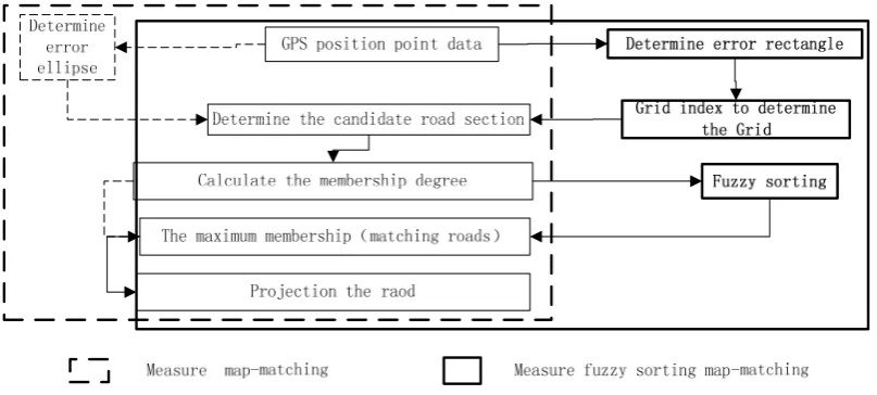
membership function and fuzzy sorting are introduced into the map-matching algorithm and the measure fuzzy sorting map matching algorithm is put forward(Fig.1 ). The algorithm is described as follows:
(1) acquiring the GPS positioning data including the location and the heading;
(2) using rectangle error region instead of error ellipse region;
(3) determining the current grid through the grid index; (4) filtering the candidate road sections according to the rectangle error region;
(5) calculating the membership degree for each two candidate sections according to the matching function;
(6) sorting adaptive fuzzy according to the membership degree of all candidate road section;
(7) selecting the candidate with the maximum membership as the matching road section;
(8) calculating projection from the GPS position located directly to the matching road section, which means the projection point is the matching point.
The algorithm compares the road membership value of candidates by fuzzy sorting, and adjusts the measure coefficient to improves the accuracy of map matching.
Figure 1. Main flow for map-matching algorithm based on measure fuzzy sorting
From Fig. 1, we can see that the differences between the measure fuzzy sorting based map matching algorithm and other algorithms are the error region determination, the road grid index and fuzzy sorting etc.
A. Determine the Error Rectangle
GPS positioning error ellipse is used to express the positioning error region. According to the references, the calculating formula of the error ellipse is shown as follows:
2 2 2 2 2
0 1
( 4 )
2 x y x x xy
a=δ δ +δ + δ +δ + δ
2 2 2 2 2
0
1( 4 )
2 x y x x xy
b=δ δ +δ − δ +δ + δ
Here: a is the major semi-axis of the ellipse, and b is
the minor semi-axis of the ellipse.
δ
0 is the extend factors,x
δ
andδ
y is the standard deviation of the GPS measuring error. and are the variances;δ
xyand
δ
yx is the covariance.It should be noted that The calculation of locating candidate road sections from the error ellipse is more difficult than rectangle region. The external rectangle of the error ellipse is substituted for the error ellipse. As the GPS position error is about 100m, the length of the error region will be set 100m in our study.
B. Calculate Roads Grid Index and the Candidate
Road Section
numbers of every grid et al. The key of these indicators is the size of the grid. If the size of the grid is too large, the amount of the road sections within the grid is overmuch, which can reduce the efficiency of spatial query. Otherwise, if the size of the grid is too small, there are large numbers of duplicate records between the grids, which causing a large amount of redundancy. Taking the single frequency GPS for the example, if the size of the grid is set to 100m, the accuracy exceeds 95%. So in our study, we set the size of the grid to 100m.
(1)Roads grid division and grid index construct
Taking 100m as the step size, the road network was divided equally into M * N grids , abbreviated as Grid ( M * N ), from top to bottom, from left to right, where M and N respectively means the number of rows and columns. For each grid, it needs to record all the code of sections including or crossing this grid, and to preserve the coordinate of the grid upper left corner as its initial coordinates. And then, we need to index the grid in order to locate quickly. This step needs to be completed when loading road layer data in initialization phase.
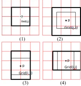
(2)Candidate road sections determination
In order to decide the candidate road sections, the grid must firstly be determined in which the GPS position point lies, and then all the roads in the gird must be selected as the candidate road sections. According to the location of the GPS position point, there are four relations between the GPS position point and the road grid (as shown in Fig2). First is the GPS position point at the nodes of the grid. The second is the GPS position point in the grid. The third is the GPS position point in the column edge of the grid. And the last is the GPS position point in the row edge of the grid.
In the relation and the error rectangle, we expand the rectangle error region according to the gird in order to simplify the candidate road sections selection. For the first circumstances, the rectangle error region expands for 4 grids (the bold black line grid as shown in Fig2). For the second, the rectangle error region expands for 9 grids (the bold black line grid as shown in Fig2). For the third and the fourth, the rectangle error region expands in horizontal and in vertically separately for 6 grids (the bold black line grid as shown in Fig2).
All the roads in the rectangle error region are the candidate road sections.
(1) (2)
(3) (4)
Figure 2. relation between the GPS position point and the Grid
(3)Candidate section measure fuzzy sorting
According to the membership function, we can calculate the
membership
values Mi (r) and Mj(r) foreach two candidate road sections i and j, and the value reflects the measure degree between the two candidate road sections separately.
The definition of the vehicle relativity function:
f (xi│xj)= Mi(r)/ max{ Mi(r) , Mj(r)}
Calculate the vehicle relativity function for all candidate roads, and define comparison matrix as:
⎪⎭ ⎪ ⎬ ⎫
⎪⎩ ⎪ ⎨ ⎧
=
) /x f(x )
/x f(x ) /x f(x
) /x f(x )
/x f(x ) /x f(x C
n n 2
1 1 n
n 1 2
1 1 1
And then calculate the minimum value for every row,
C i′= min f (xi│X) i = 1, 2, ⋯, n
C i′ is the membership value for the candidate road
section i.
According to the introduction in chapter[3.1], The road section with the largest membership sort value is the matching road section(CMR). That is :
CMR= max(C i′)=[min f (x1│xi), minf (x2│xi) , , min f
(xn│xi)]T i = 1, 2, , n
V. ALGORITHM ADAPTABILITY ANALYSIS AND PROCESSING FOR VEHICLE NAVIGATION
Any algorithm has its adaptability. Therefore, to improve the robustness and the efficiency of the algorithm, different processing methods is designed for different vehicle cases. For example, when the match road section is very clear, calculating the matching road section is not necessary and a simple projection can implement map matching. According to the requirement of the vehicle navigation, five kinds of vehicle running statuses are designed(shown as fig 3), which are road search status, normal driving status, delay matching status , parking or low-speed status and signal errors status..
A. Road search Status
Map-matching algorithm starts when the matching road is not determined, such as in the initial state and the intersection state. In this case, fuzzy sorting matching algorithm can be used directly and the GPS position point can be projected into the matching road section that has the maximum membership degree.
B. Vehicle Normal Running Status
If the GPS position point is not in the range of intersection (not entered or left), and at the same time the current matching road section is determined, or the GPS position point is in the intersection, and road search has been completed. In above state, according to the road connectivity rule, it is not need to search the matching road section but to project the GPS position point into the identified road directly.
C. Delay Matching Status
very small, for example, less than the threshold condition (generally set to 0.1-0.2), it means that the road condition is complex and it is difficult to judge which one is the suitable matching road section. In this case, the delayed matching is needed until the matching road section can be determined.
D. Vehicle Parking or Low-speed
When the vehicle is stopped or low-speed, the vehicle location should be in motionless state in theory. However, because of the random drift of GPS positioning error, the vehicle position information given by the GPS is often randomly shift within a region. In this case, the current matching point can be seen as the current location of the vehicle until the vehicle is on.
E. GPS Data Exception
If the distance between two continuous GPS position point is significantly higher than the normal range, it can be seen as the GPS data exception. In our design, it is twice than the normal value. In this case, it is required to calculate the vehicle location though the linear interpolation according to the historical vehicle trajectory.
Figure 3. Map-matching flowchart with vehicle different running statuses
VI. IMPLEMENT OF MEASURE FUZZY SORTING BASED MAP-MATCHING ALGORITHM
Taking the roads of Fuzhou city as an example, there are 91 GPS position points. the algorithm is implemented according these points.
A. Data Pre-processing
The coordinate of the electronic map is the Gauss projection coordinate system under the Xi’an-80 geographic coordinate system. But the coordinate of GPS
position point is WGS-84 coordinate system, which has the different ellipsoid and the geodetic datum with Xi'an 80 coordinate system. To make sure they are in same coordinate system, the coordinate of GPS position point need to be converted into the Gauss projection coordinate system under Xi'an- 80 geodetic coordinate system. There are two steps of the data pro-processing. The first is to transform the WGS-84 coordinate system of GPS position point into Xi’an-80 geodetic coordinate system. The second is to transform the geographic coordinate system into projection coordinate system though the Gauss projection.
B. Algorithm Design Patterns according to the Vehicle
Running Status
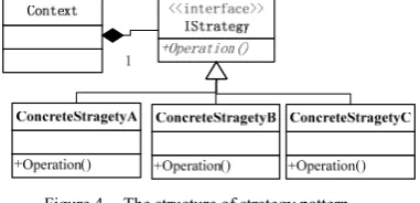
The Strategy Pattern defines a family of algorithms, encapsulates each one, and makes them interchangeable. Strategy lets the algorithm vary independently from clients that use it. The structure of the strategy is shown in Fig4. It is very suitable to use strategy pattern to deal with the vehicle running status changes.
Figure 4. The structure of strategy pattern
From the chart we can see: strategy pattern is actually to package the algorithm separately, such as the ConcreteStrategyA, ConcreteStrategyB and ConcreteStrategyC. They are inherited from an interface in order to realize the algorithm calls with polymorphic manner when Context called them.
According the vehicle’s five running conditions, which include road search status, normal driving status, delay status, parking or low-speed status and signal error status, we built five algorithms separately. In order to call the different algorithm, we use the strategy patterns to package them. The UML class diagram is shown in Fig5.
Figure 5. The UML class diagram of strategy patterns
C. Fuzzy Sorting Algorithm Implementation
of the candidate road section to calculate the membership degree. Then, FuzzyRank class sorts the candidate road sections according the membership degree calculated by MembershipCalculator class and selects the candidate road section with the maximum membership degree as the matching road section.
Figure 6. The fuzzy sorting class interfaces
D. Grid Index Construct
GridsBuilder class is to implement the Grid index, (shown as fig7) which gets access road entity and sets through the IPolylineFeatureCollection interface. Then the class divides the grid by the grid size(Width) and generation Grid type list. ,It also stores the road entity (IPolylineFeature) within each grid in the corresponding grid object road entity set ( Features ).
Figure 7. The grid index construct class interfaces
E. Candidate Road Sections Filter
The RouteFilter class is to implement the filter of candidate road sections.
Firstly, according to the GPS position point, Rect Class determines the grid location. The binary search algorithm is used to accelerate the search speed. Secondly, ErrorRegion class constructs the error region rectangle. Finally, the candidate road sections set (IPolylineFeatureCollection) will be generated though filtering all the road sections within the error region rectangle.
Figure 8. The candidate road filter class interfaces
VII. EXPERIMENT AND RESULT ANALYSIS
Due to the complexity of algorithm, it would take a little more time than others, but the result got the highest accuracy, which is the most important for terminal users.
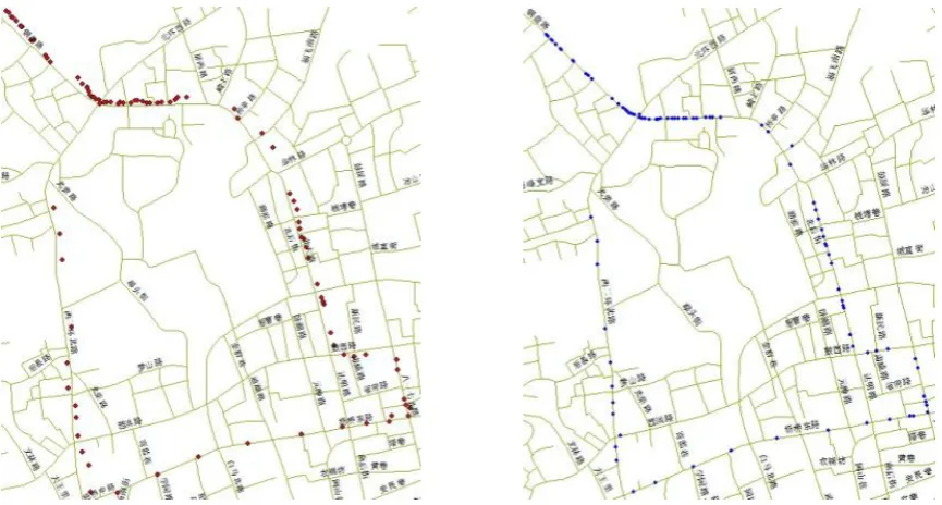
In this experiment, there are total 91 GPS positing point. Through the calculating, the matching-map result is shown in Fig9. The number of matching point is 88, which means the accuracy of our alogorithm is 96.7%, the total time cost is 9000ms, and the single point time cost is 99ms.
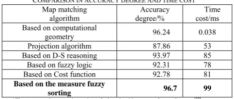
The comparison with other algorithms is list in table 1. Compared with other algorithms, our algorithms accuracy is obviously improved, the algorithm complexity is elevated which leads to the computation time is longer, so we need to be further improved to reduce time-consuming.
TABLE1
COMPARISON IN ACCURACY DEGREE AND TIME COST Map matching
algorithm
Accuracy degree/%
Time cost/ms Based on computational
geometry 96.24 0.038
Projection algorithm 87.86 53 Based on D-S reasoning 93.97 85 Based on fuzzy logic 92.31 78 Based on Cost function 92.78 81 Based on the measure fuzzy
sorting 96.7 99
*The accuracy degree and cost time of other algorithm comes from references [27]
VIII. CONCLUSION
IX. ACKNOWLEDGEMENT
This paper is supported by FP7-PEOPLE-IRSES (No.247608), Fujian Province Nature Science Foundation
(No: 2012J01168), National Technology Support Project (No: 2013BAH28F00). I would like to thank the members of my committee for their support.
Figure 9. The original GPS position point and the results of map-matching
REFERENCES
[1] J. Su, D.F. Zhou, C.S. Yue. “Real-time map-matching algorithm in GPS navigation system for vehicles,” Acta GeoDaeticaet Cartographica Sinica, vol. 30(3), pp.252-256, 2001.
[2] M.A. Quddus, W.Y. Ochieng, R.B. Noland. “Current map-matching algorithms for transport applications: State-of-the art and future research directions,” Transportation Research, vol. 15(3), pp.312–328, 2007. [3] M.A. Quddus, W.Y. Ochieng, L. Zhao, R.B.Noland. “A
general map-matching algorithm for transport telematics applications,” GPS Solutions, vol. 7 (3), pp.157-167, 2003.
[4] C.E. White, D. Bernstein, A.L. Kornhauser. “Some map matching algorithms for personal navigation assistants,” Transportation Research Part C, vol. 8, pp.91-108, 2000. [5] D. Bernstein, A. Kornhauser. “An introduction to map
matching for personal navigation assistants,” Technical report, New Jersey TIDE Center Technical Report, 1996. [6] B. Phuyal. “Method and use of aggregated dead reckoning
sensor and GPS data for map-matching,” In: proceedings of the Institute of Navigation (ION) annual conference, 2002.
[7] M.A Quddus.. “High integrity map-matching algorithms for advanced transport telematics applications,” PhD Thesis. Centre for Transport Studies, Imperial College London, UK, 2006.
[8] Y. Meng. “Improved Positioning of Land Vehicle in ITS Using Digital Map and Other Accessory Information. PhD Thesis,” Department of Land Surveying and Geoinformatics, Hong Kong Polytechnic University, 2006.
[9] C. Wu, Z.L. Li, M. Yu, Y.Q. Chen. “Effects of sensor errors on the performance of map-matching ,” Journal of
Navigation, 2005.
[10] H. Yin, O. Wolfson. “A Weight-based map-matching method in moving objects databases, Scientific and Statistical Database Management ,” In: Proceedings of the International Working Conference, vol. 16, pp.437-438, 2004.
[11] C.A. Blazquez, A.P. Vonderohe. “Simple map-matching algorithm applied to intelligent winter maintenance vehicle data,” Transportation Research Record, 2005. [12] R.V. Nagendra, A.Q. Mohammed, L.B. Abigail.
“Developing an enhanced weight-based topological map-matching algorithm for intelligent transport systems ,” Transportation Research Part C: Emerging Technologies, vol. 17(6), pp.672–683,2009.
[13] S.K. Honey, W.B. Zavoli, K.A. Milnes, A.C. Phillips, White MS, Loughmiller GE. “Vehicle navigational system and method ,” United States Patent, 1989.
[14] F. Chen, M.Y. Shen, Y.N. Tang. “Local Path Searching Based Map Matching Algorithm for Floating Car Data,” Procedia Environmental Sciences, vol. 10(A), pp.576-582, 2011.
[15] E.J. Krakiwsky, C.B. Harris, R.V.C. Wong. “A Kalman filter for integrating dead reckoning, map matching and GPS positioning,” In: Proceedings of IEEE Position Location and Navigation Symposium, pp. 39-46, 1988. [16] W. Kim, G. Jee, J. Lee. “Efficient use of digital road
map in various positioning for ITS,” In: IEEE Symposium on Position Location and Navigation, San Diego, CA, 2000.
[17] M.E. El Najjar, P. Bonnifait. “A road-matching method for precise vehicle localization using belief theory and Kalman filtering ,” Autonomous Robots, vol. 19(2), pp.173-191, 2005.
14(5), pp.448-452, 1999.
[19] Y.J. Cui. “Autonomous vehicle positioning with GPS in urban canyon environments ,” IEEE Transactions on Robotics and Automation, vol. 19 (1), pp. 15-25, 2003. [20] D.K. Yang, B.G. Cai, Y.F. Yuan. “An improved
map-matching algorithm used in vehicle navigation system ,” IEEE Proceedings on Intelligent Transportation Systems, vol. 2, pp.1246-1250, 2003.
[21] X.Y. Yang, S.G. Huang. “Map Matching Algorithm Based on Road Reduction Filter in Integrated Vehicle Navigation System ,” Journal of remote sensing, vol. 9 (2), pp.215-219, 2005.
[22] M.Y. Fu, J. Li, M.L. Wang. “A hybrid map-matching algorithm based on fuzzy comprehensive Judgment ,” IEEE Proceedings on Intelligent Transportation Systems, pp.613-617, 2004.
[23] M. Cossaboom, J. Georgy, T. Karamat, A. Noureldin. “Augmented Kalman Filter and Map Matching for 3D RISS/GPS Integration for Land Vehicles,” International Journal of Navigation and Observation, 2012.
[24] M.A. Quddus, R.B. Noland, W.Y. Ochieng. “A high accuracy fuzzy logic-based map-matching algorithm for road transport,” Journal of Intelligent Transportation Systems: Technology, Planning, and Operations, vol. 10 (3), pp.103-115 , 2006.
[25] E. J. Krakiwsky, C. B. Harris, R. V. C. Wong. A Kalman filter for integrating dead reckoning, map matching and GPS positioning. Position Location and Navigation Symposium, 1988. Record. Navigation into the 21st Century. IEEE PLANS '88., IEEE (06 August 2002), pp. 39-46.
[26] S.J. Julier; J.K. Uhlmann."Unscented filtering and nonlinear estimation". Proceedings of the IEEE(2004): 401–422.
[27] E. Courses; T. Surveys. "Sigma-Point Filters: An Overview with Applications to Integrated Navigation and Vision Assisted Control". Nonlinear Statistical Signal Processing Workshop, 2006 IEEE: 201–202.
[28] P. Davidson, J. Collin, J. Takala. “ Application of particle filters to a map-matching algorithm. Gyroscopy and Navigation, vol.2(4), pp.285-292, 2011.
[29] Sh. Sun, J. Gao, M. Chen, B. Xu, Zh. Ding. “FS-DS based Multi-sensor Data Fusion”, Journal of Software, Vol. 8( 5),pp. 1157-1161, 2013.
[30] M.Y. Fu, Z.H. Deng, T. Liu. “Intelligent vehicle navigation technology,” Science Press, 2009.
[31] A.B. Carola. “A Decision-Rule Topological Map-Matching Algorithm with Multiple Spatial Data,” Global Navigation Satellite Systems: Signal, Theory and Applications, InTech, 2012.
[32] M. Yan. “Dominance-based Rough Interval-valued Fuzzy Set in Incomplete Fuzzy Information System”. Journal of Software, Vol. 7( 6),pp. 1375-1384. 2012.
[33] J. Li, G. Liao, F. Wang, J.i Li. “Maximum Lifetime Routing Based on Fuzzy Set Theory in Wireless Sensor Networks”. Journal of Software, Vol. 8(9) pp.2321-2328, 2013.
[34] S. Masamichi. “Fuzzy sets concept in rank-ordering objects,” Journal of Mathematical Analysis and Applications, vol. 43 (3), pp.717 -733, 1973.
Qunyong Wu, male, was born in 1973, in Shandong China. .He received the Bachelor's degree and the Master's degree in Computer Application respectively in 1996 and in 2002, from Fuzhou University, Fujian, China. He received Doctor's degree in Cartography and geographic information system in 2006, from Key Lab of Graduate School, Geographic Sciences & Natural Resources Research Institute, and Resources & Environment Information System in China Academic of Sciences, Beijing, China.
He used to involve in education and research of computer application in Computer Department of Fuzhou University between 1996 and 2000. During 2000 and 2001, he took part in the research of Geographic Information Science and Technology Institute. Since then, he has been working as assistant researcher, vice researcher and instructor in Spatial Information Research Center of Fujian, Fuzhou University, China. Besides, he has been also a member of Key Lab of Spatial Data Minging and Information Sharing (Fuzhou university) from 2004. His research interests are network geographic information sharing and service, and geographic information system software development.
Xiao-ling Gu, femal , was born in Jiangxi, China, in 1989.She received the Bachelor's degree in Geographical Information System in 2011, form China University of Petroleum(East China), Qingdao, China. She is currently a postgraduate at Spatial Information Research Center of Fujian in Fuzhou University, Fujian, China. Her research interest is geographic information sharing.
Jianping Luo, male, was born in Sichuan, China, in 1986. In 2009, He received the Bachelor's degree in Resource Environment & Urban and Rural Planning and Management in Anhui Construction Industry Institute in Hefei, Anhui. In 2013, he earned the Master’s degree of Cartography and geographic information system in Spatial Information Research Center of Fujian in Fuzhou University, Fujian, China. His majority researches are geographic information sharing and service technology, and moving objects database.
Panpan Zhang, male, born in 1986 in Henan, China, received his Bachelor’s degree in School of Resources and Environment of Henan Polytechnic University, Henan, China, in 2008 and got Master’s degree of Cartography and geographic information system in Spatial Information Research Center of Fujian in Fuzhou University, Fujian, China in 2011.
Now he is working in Beyon Information Technology Co. Ltd. in Beijing, China, as a software engineer. His research interests are geographic information service and spatial database management system.