“Killing Spillage”: An algorithm to reduce
microphone spillage and improve phase
coherence.
A Work in Progress.
Justin Paterson, London College of Music, Thames Valley University The 2nd Art of Record Production Conference, Edinburgh, September 8th-10th 2006
Correspondence should be addressed to Justin Paterson [[email protected]]
ABSTRACT
Since the earliest days of multi-microphone live recording, the problem of spillage has dogged the sound engineer. Numerous strategies have evolved including microphone placement, acoustic screening, gating and phase inversion. The acoustic content of spillage can vary from a near direct signal in the case of adjacent mics on a drum kit to almost pure reverb in the case of a live recording with acoustically significant spacing between the performers. In certain physical setups, the problem is unavoidable and inevitably compromises the degree of control that can be exercised when mixing. It is principally for this reason that it is considered ‘a problem’.
If spillage could be tamed, then the impact on all production would indeed be profound. Classical recordings might afford the producer radical new “Rock’n’Roll” interventionist techniques. Rock producers might be tempted to allow bands to play live in a room even when a highly “separated’ sound is the ultimate goal, and jazz musicians might avoid having to wear the headphones they so often dread. That is only the beginning.
This paper will present a radical new working methodology that can dramatically reduce spillage in a way never before possible by utilising convolution technology that could be coupled with almost any “traditional” recording technique, but will focus on time-delayed and ambient problems. A unique Max/MSP patch will be demonstrated and audio
examples will be played to illustrate the effectiveness of the approach. It will delve into commonly understood theory yet demonstrate for the first time, one of tomorrow’s “traditional” recording techniques.
1. INTRODUCTION
A fundamental limitation of current record production is the extent to which the various multi-track components of a recording can be manipulated individually. Broadly
separate entities, applying processing as deemed appropriate to each of those component tracks.
The former method is traditionally favoured in classical and often jazz recordings, the latter in rock and popular.
If extensive intervention is anticipated, each recorded signal must contain as little information as possible from the other signal(s). If elements of the undesired audio do become embedded in the recording of something else, then any subsequent manipulation will not just affect the target signal, but also exert some influence over the intruding signal which may in turn cause unwanted artefacts when both signals are played back simultaneously as components of a multitrack mixdown. Even in the “acoustic” style mentioned above, processing as basic as equalisation is likely to lead to subtle phase related timbral differences in such a recombination, and so both of the above production approaches could benefit from enhanced separation.
Fig. 1 Target Signal: eg
a saxophone
Spillage: Intrusive Signal- in this case coming from a bass. This instrument will typically have its own dedicated microphone too, omitted here for clarity
This intrusion is commonly known as “Spillage” and is a feature of all multi-microphone recordings unless microphones (and musicians) are placed in acoustically isolated
separate rooms. Fig. 1 shows a graphical representation of this scenario.
Such placement of musicians is commonly employed, but inevitably leads to an unnatural feeling for the musicians, which can degrade their quality of performance. An alternative might be to have musicians sharing a room to facilitate eye contact and concentrate performance “energy”, and again in this scenario, it is common practice to erect acoustic screens that allow partial attenuation of this spillage.
The overdub approach can of course negate this, but that is not relevant to this discussion. Another strategy is the use of noise gates that allow a clear signal path only when open, activated by the amplitude of the target signal. Frequency conscious gates allow a modest amount of tuning to the principal frequency components of the target signal, but these still only act in the amplitude domain. When open, gates will pass the spillage alongside the target signal, often with the consequence of level fluctuations when the multi-track components are recombined since the spilling signal is always present through its own microphone, and the adjacent track’s gate will open intermittently as a function of the target signal passing through the gate. The gating approach often dictates a stylistic sound to the resultant mixdown, but it is not deemed compatible with every genre or individual piece of music.
It might be noted at this point that although the commonly understood concept of phase cancellation of signals is most efficient in theory, this process is incredibly sensitive to both amplitude and timing differences. It can be employed in situations of cross-talk on multi-track tape, but is not a powerful weapon in the scenario described above since both time delays and amplitude mismatches are present at the point of signal summation.
1.1 BACKGROUND
The Author’s own context for investigating this field arose out of a project of a different nature. This will be briefly described simply to contextualise what follows.
It was the Author’s desire to record a group of free-improvising musicians in the jazz idiom, and subsequently produce reconstituted compositions from the component parts of the multi-track recording. Juxtaposition editing of audio fragments might be aesthetically pleasing through their harmonic and rhythmic content alone, however if the juxtaposed audio also contains fragments of spillage, then it is more than likely that the result will be less musically successful, and so isolation is essential. In addition to this, it was planned to construct a patch in Max/MSP that could analyse a fragment of audio and exert a “re-improvisation” (based on this analysis) upon some other piece of audio simultaneously. This process would be made near impossible in the presence of spillage, since the patch would have to be able to recognise both pitch and rhythm, and subsequently execute one of a number of stochastic processing algorithms. This approach could only work on a “clean” recording since any spillage would create mixed messages for the algorithm to act on.
artists. In discussions with the band, they underlined the need for eye contact, thus putting them in the same acoustic space.
The principal recording studio at the London College of Music is adjacent to a large live performance area; the only space with a suitable piano. Baffles were available, but the height of the ceiling rendered them rather ineffective, see Fig.2. There was however a separate live room which was configured with a video link for the drummer in order to remove this loudest instrument from the principle acoustic space.
An ambient album was recorded in these circumstances- “The Making of Quiet Things”, and the band christened “The Number”, (SLAMCD 269) 50 28386 02692 1.
Upon analysis of the multi-track recordings, it was found that as anticipated, there were significant amounts of spillage on many channels, which limit subsequent development of the Max patch and the creation of the new compositions.
Fig. 2
It was frustration at having to compromise the desired manipulations that motivated the Author to investigate ways of controlling spillage.
2. THE ROOM MODEL
In pursuit of spillage removal, the simplest possible room model was formed. The black arrows in Fig. 3 show the direct signal path from instrument to dedicated microphone. Such a signal is assumed to be relatively instantaneous and relatively free from room ambience.
Fig. 3
The brown arrows represent the spillage from the intrusive signal. This will comprise of the direct sound of that instrument, although time-delayed due to the relatively large spatial separation with some degree of attenuation according to the Inverse Square Law, and room ambience which will appear as a function of the relative placements of each instrument and microphone in the room. This model could easily be iterated to take account of multiple microphones/instruments.
It is evident from viewing spillage in this way that it has two principle components: 1) A time-delayed version of the intrusive signal
2) The unwanted instrument’s room ambience, as “perceived” by the target instrument’s microphone.
Obviously, this is an over-simplified scenario, which does not take account of such things as the well understood high frequency loss as the intrusive signal passes a relatively large distance, the actual (small) time delay for the target sound to reach its dedicated
microphone, and the inevitable (relatively small) amount of room ambience of the target instrument that will also be recorded into the target microphone. These factors may be investigated in future work.
3. PRINCIPAL OBJECTIVES
The specification of the required device might therefore present itself as follows. It must:
A] playback a minimum of 2 audio files, preferably with loopable control
B] be able to evaluate and then compensate for time delays (to sample accuracy) induced by the physical separation of instruments (microphones)
C] be able to perform sample accurate phase reversal
D] be able to evaluate and then compensate for level differences, possibly dynamically E] be able to recreate the ambience of the acoustic space so that this can counter the natural ambience on the spilling signal
The flexibility and power of Max/MSP makes it an ideal medium to carry out tasks A-D. Task E is also possible within Max/MSP, however after investigation of current
commercially available packages, it was felt that “Audioease Altiverb” would produce the most accurate room emulation. This could be integrated within Max/MSP as a VST instrument. Budgetary restrictions meant that it was not possible to carry out quantitive measurements of efficiency of other commercial room emulation software, however it was decided to proceed with the design in order to evaluate the overall efficiency of the algorithm and then if necessary, compare other manufacturers’ emulations
retrospectively.
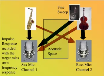
4. ROOM EMULATION
The emulation of the room’s acoustic is a crucial aspect of the algorithm’s success. Commercial convolution reverb units such as Audioease Altiverb feature the ability to excite a room through the full range of audio frequencies and reproduce its reverberant response. This is most faithfully achieved with a Sine Sweep [1]from 20Hz to 20kHz. The sweep is played back through a specific monitoring device which has had its characteristics modelled by the manufacturer, and the ambient response is recorded. A utility supplied with the software then performs a deconvolution upon the recording to remove the actual sine sweep, leaving an Impulse Response (IR) of the room’s
reverberation that the Altiverb unit can then impose upon any audio signal passing through it.
The standard application of such a convolution reverb is in the modelling of concert and post-production spaces, and so the emphasis in recording practice is upon creating a full range and spatially accurate response, and typically uses (multiple) pairs of reference microphones to capture this.
The application in this paper is not to create an “all purpose stereophonic musical reverb”, but rather to simply reflect the apparent effect of the room on a single
acoustic space. Here lies a convenient aspect of this algorithm. When recording, the producer/engineer will typically wish to place a preferred microphone at a precise position relative to the target instrument. This microphone will of course have its own particular characteristics that colour the sound in a (hopefully) desirable fashion. Once placed accordingly, if this very microphone is used to capture the monophonic IR of a sine sweep placed very close to the Intrusive instrument’s physical position, then the IR generated will already contain the colouration of the Target’s microphone (including the likely off-axis response), thus negating the need to use a separate reference microphone, and the IR will truly reflect the subjective effect of the ambience on the Intrusive signal. See Fig 4 for a schematic of this revised recording scenario.
Fig. 4
If this IR was then loaded into Altiverb and applied to the (idealized; dry and
instantaneous) signal from the close microphone at the intrusive instrument, then the effect should be that the processed signal of Channel 2 is similar to the intrusive signal in Channel 1.
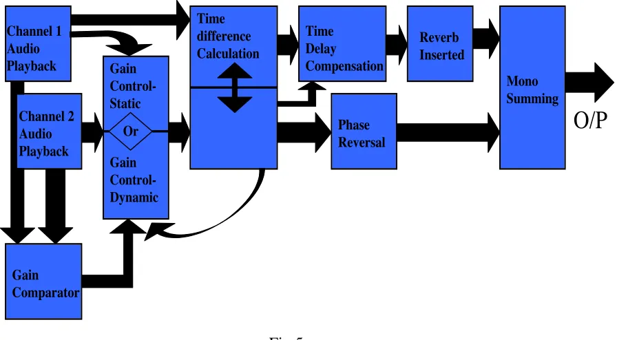
5. THE ALOGRITHM
Fig. 5 below represents the algorithm needed to develop the Max patch.
Channels 1/2 Audio Playback: The two channels represent audio recordings from two microphones (of any instruments) as might be in Fig. 4. Typically, the user will select a looped region of audio around a transient in the signal to allow subsequent detection of a maximum- see below.
Gain Control- Static: The user can manually compare the gain of the two signals using meters and apply an offset to match if deemed suitable.
Gain Comparator/ Gain Control- Dynamic: Alternatively, both channels are fed into a gain comparator, which allows dynamic level automation locking Channel 2’s peak (future work will facilitate RMS for evaluative comparison of efficiency) to that of Channel 1, purely for the purpose of cross-correlation. Certain material might prefer static gain, whilst certain others might require dynamic.
Time Difference Calculation: The waveforms are analysed with a peak detection algorithm. Channel 1’s time base is iteratively shifted until phase coherence of the
transient is detected by recording the time shift that produces the maximum instantaneous gain when the channels are summed. A convenient aspect of such a subjective approach is that the (short) time delay induced by the Intrusive instrument’s dedicated microphone will become irrelevant since only the difference contributes to subsequent phase
The One-T Algorithm:
Block Diagram structure
Channel 2 Audio Playback Gain Control-Dynamic Gain Comparator Channel 1 Audio Playback Time difference Calculation Reverb Inserted Time Delay Compensation Gain Control- Static Or Phase Reversal Mono Summing
O/P
So, with adding mono summing, channel
1 is time delayed to lock with Channel 2 and given
reverb characteristics as Channel 2’s mic would
perceive it. Since Channel 2 is out of phase with it,
when summed, the resultant output will be a pure
(phase reversed) Channel 2.
compensation.
It has long been established that the generalised cross-correlation (GCC) method can estimate the delay present between two sensors [2], however this was shown not to work well in a reverberant environment [3]. This is a good reason to adopt this lateral
approach.
“In the reverberant environments, the performances of the conventional Time delay Estimator (TDE) methods are degraded due to interference and
reverberation [3]. The main reason is the disagreement between the ideal propagation model and the real signal model in reverberation [3][4].
Therefore, the TDE for the MA system should take account of the room transfer function (RTF) that models the room reverberation [4]. “ [5]
The work of [5] is primarily aimed at adaptive microphone arrays, but it would seem to imply that current technology has not yet addressed the simple convergence of transients, instead the focus being on Fourier based spectral analysis.
Time Delay Compensation: The optimum Time Difference Calculation above is fed into a sample accurate delay line. The user can then lock the delay (phase) at this optimum.
Phase Reversal: Channel 2 is phase reversed which allows potential cancellation of the direct signals.
Reverb Inserted: The reverb created from the IR of the room with Channel 2’s mic is inserted into Channel 1’s path. Since Channel 1 is already delayed and phase inverted to match Channel 2, this reverb will be an “inverse” of the physical room response carried by the intrusive signal into Channel 1. Experiments showed that Altiverb 5 would mathematically produce a phase inverted response when configured post-phase reversal. There were a number of issues encountered, not least the erroneous latency reported by Altiverb when in Max/MSP.
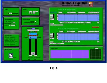
6. THE MAX PATCH
A Max/MSP patch was created to implement the above algorithm. Precise details will be available in the final multi-media version of this paper. The patch was christened “The One-T”. Fig. 6 shows its GUI. The two channels can be seen on the right, and beneath them, a spectroscope and oscilloscope to aid the user assess the functionality of the algorithm.
Fig. 6
7. RESULTS
7.1OPERATION
Once the IR is recorded, normal music recording can commence assuming no further microphone placement adjustment occurs.
7.2 TESTING
A number of audio examples were prepared:
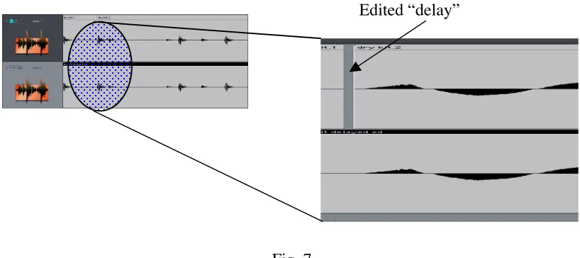
7.2.1 A digital drum loop was created and a random cut was introduced into a clone of the loop to introduce an edit-delay in part of the audio. See Fig. 7. This audio was then rendered to form a contiguous file to compare with the unedited source audio. Both audio files were loaded into the patch.
Fig. 7
When a transient was selected and the patch asked only to calculate the delay, it was found that indeed the process was sample accurate. This was verified by phase inverting the second piece of audio, and complete cancellation from the original edit point was noted. Moving the delay manually by a single sample in either direction allowed images of the signal to audibly reappear, additionally verifying that sample accuracy was necessary in this process.
This is clearly an idealised task since the audio is identical apart from a time delay, however it was necessary to verify that this part of the algorithm functioned correctly.
7.2.2 If the gain of the second audio segment was lowered to emulate the attenuation associated with real world distance, the cancellation was found to be less effective. Switching in the dynamic level matching circuit alleviated this and again complete cancellation was noted, verifying that this was certainly necessary for certain circumstances and again, the algorithm worked in the idealised scenario.
7.2.3 In order to evaluate the delay compensation in a more real-world situation, two sE Titan microphones were set up above a tom-tom, placed at deliberately different
distances as shown in Fig. 8.
Fig. 8
The patch indicated that a precise lock of transient should occur at 125 samples (at 44.1kHz sample rate), which equates to 2.834ms.
Using:
t=d/s Equation [1]
with a value of 340m/s for the speed of sound (an approximation dependant on the hygrometrics, pressure and temperature of the environment), Equation [1] calculates the delay as 2.794m/s. This is equivalent to a spatial error of around 1.5 cm, which could easily be a function of (the fairly crude) measurement or the above approximation. More accurate analysis of this nature was not deemed necessary since this was not the primary focus of the experiment.
More relevant was the profound audible enhancement of the transient of the tom-tom. It showed that not only did the delay compensation work in the real world, but also that improved phase coherence of transients was possible through the system.
7.2.4 Testing now moved to the accuracy of the IR recording process. A test scenario was constructed in a large domestic hallway. Again sE Titans were employed, but this time with separate sound sources; a spoken voice at one end of the hall and a hand clap at the other. The rationale was that a hand clap would be perceived with a large proportion of reverb across the hallway, and so any audible attenuation would be most evident. Speech
was used as representative of a real world complex signal without too much inherent volume to drown out the spillage from the clap. The adjacent ends of the test recording setup are shown in Figs. 9 and 10.
Fig. 9 Fig. 10
Audioease recommend use of a Genelec S30 to create IR’s since they have modelled this monitor’s response accurately. A budget alternative was the Tannoy Reveal, which although modelled equally, is not subject to the same manufacturing consistency as the Genelecs, and does not have such an accurate full range audio response. The sine sweep was noticeably “flappy” at low frequencies. Only a Reveal could be sourced in the time frame for this experiment.
Unfortunately, upon recording the IR, it was found that the full range sine sweep caused numerous antique artefacts present in the hall to rattle at their characteristic resonant frequencies, and so combined with the imprecision of the Reveal’s performance, the IR was deemed unsatisfactory. Fig. 11 shows the offensive “rattley objects”.
Despite this, when the IR was fed back into the instance of Altiverb embedded in the Max patch, some audio effects were noted. There was a most audible interaction of ambience and phase reversed ambience, and although there was some of the marked attenuation hoped for, the characteristic of the resultant audio was modified, rendering the final validation inconclusive. Unfortunately it was not possible to replicate the experiment in more controlled conditions within the conference schedule.
8. EVALUATION
There is considerable optimism that when correct IR’s are utilised, the patch will function as hoped, at least partially. Even spillage attenuation of 15dB would prove most useful in typical recording session, so the panacea of complete removal may not need to be
achieved at this stage. The single biggest variable that might prevent this are the imperfections inherent in Altiverb and the IR generation process. Audioease will not discuss know errors in their speaker modelling, and it is envisaged that any imperfections here will affect the profundity of the final outcome in this context. It is whether they will prove good enough to be useful which is still open to further experimentation. Even if the algorithm was proven partially successful, the commercial motivation to create an
optimised rig for such purposes would be significant. Post conference, further
experimentation showed that Altiverb did not report the correct latency value (which had been compensated for in the patch) and it could be that refining this aspect of the patch could contribute significantly to the overall success of the project.
The simplicity of the model has yet to be fully evaluated. Whilst it is robust in theory, ignoring the intrusive signal’s microphone ambience could clearly present problems. Such ambience will be a function of the polar pattern and placement.
The SPL of the source will also be relevant since louder sounds will tend to drive the room more significantly and increase the amount of ambience created and captured by the close microphone(s).
High frequency loss over the distance between the target and intrusive source location has been ignored similarly, although this will certainly be subjectively compensated for to some degree by the placement of the sine sweep monitor at an equivalent distance from the target microphone.
9. FUTURE DEVELOPMENTS
Numerous possibilities for future developments of the work present themselves:
Plug-in version: If the patch were configured as a plug-in, users could work wholly within their preferred DAW.
Audio file output capability: Easier to implement than the above, it would prove most useful for practical usage if the patch had the ability to export suitably modified audio,
Reference Microphone: Use of an additional reference microphone to capture the “dry” signal of the Intrusive instrument should yield a more accurate response since the current model allows for some unwanted colouration from the dedicated recording microphone. This would obviously be at the expense of convenience when recording since an extra microphone would have to be acquired and placed.
Integrated Reverb: The possibility of a native reverb unit in the patch would provide an integrated solution. Design of such a device would be difficult since it would have to function up to the existing accuracy of commercially available units and have the ability to create IR’s.
Multi-Channel version: Whilst current work has been on a two channel prototype, further real world adaptability would be facilitated by implementing a multi-channel version, not necessarily for 5.1, but to take account of multi-microphone situations, eg drum kit recording.
Multi-band version: It is possible that operation in the spectral domain could yield even more significant results. The current algorithm uses only a single time offset, which of course can only strictly equate to a single frequency. Phase accurate FFT partitioning of the bandwidth might prove more effective.
2 Simultaneous Convolutions: One of the assumptions of the simple model is that the intrusive microphone is capturing a dry signal. This will not actually be the case, so applying the algorithm bi-directionally could prove and effective way of countering this should it become a problem.
10. CONCLUSION
refinements. Preliminary testing has shown that the algorithm shows promise and already has great potential in the enhancement of musical transients.
REFERENCES
[1] “Making Impulse Responses from real acoustic environments for music production”
AltiverbTM Copyright © by Audio Ease, pp. 2 [2] C. H. Knapp and G. C. Carter, “The generalized
correlation method for estimation of time delay,” IEEE Trans. Acoust., Speech, Signal Processing, vol. 24, no. 4, pp. 320-327, Aug. 1976.
[3] B. Champagne, S. Bedard, and A. Stephenne, “Performance of time-delay estimation in the presence of room reverberation,” IEEE Trans. Speech Audio Processing, vol. 4, no. 2, pp. 148-152, Mar. 1996.
[4] J. Benesty, “Adaptive eigenvalue decomposition algorithm for passive acoustic source
localization,” Journal Acoust. Soc. of America, vol. 107, no. 1, pp. 384-391, Jan. 2000.
[5] Choi, Seung Jong; Jung, Yang-Won; Kang, Hong-Goo; Kim, Hyo Jin “Adaptive Microphone Array with Self-Delay Estimator”