Please cite this article as:Ch. Ghobadi , M. Majidzadeh, Multi Attribute Analysis of a Novel Compact UWB Antenna with Via-fed Elements for Dual Band Notch Function, TRANSACTIONS A: Basics Vol. 27, No. 10, (October 2014) 1565-1572
International Journal of Engineering
J o u r n a l H o m e p a g e : w w w . i j e . i rMulti Attribute Analysisofa Novel Compact UWB Antennawith Via-fed Elements for
Dual Band Notch Function
Ch. Ghobadi* , M. Majidzadeh
Department of Electrical Engineering, Urmia Branch, Islamic Azad University, Urmia, Iran
P A P E R I N F O
Paper history:
Received 11February 2014 Accepted in revised form 22May 2014
Keywords:
Analytical Hierarchy Process Dual Band-notch
Expert Choice Software UWB Antenna Via-fed Elements
A B S T R A C T
A compact microstrip-fed antenna with dual notched bands is proposed. First, a simple basic configuration is presented for Ultra Wide Band (UWB) applications and then the dual band notched structure is extended from the UWB one. The basic structure of the UWB antenna consists of a simple square radiating patch and a ground plane with a wide square slot on back of the substrate. A semi-circle shaped slot is cut from the ground plane to improve the antenna impedance matching. In the sequel, with the aim at filtering Worldwide Interoperability for Microwave Access (WiMAX) and Wireless Local Area Network (WLAN), via-fed inverted T-shaped element and two rectangular stubs are embedded in the antenna structure. The presented antenna is printed on a 20 × 20 × 0.8 mm3 FR4
substrate and operates over the frequency range of 2.9-16 GHz with WiMAX and WLAN notched. To compare the performance of the proposed UWB antenna to some previous designs, a novel framework based on the Analytical Hierarchy Process (AHP) is proposed. Using AHP methodology, the important operational aspects of antennas are taken into account simultaneously, resulting in a comprehensive comparison. Expert Choice software is used to apply the AHP technique.
doi: 10.5829/idosi.ije.2014.27.10a.10
1. INTRODUCTION1
Paving the way to make a more effective use of frequency bands, 3.1-10.6 GHz has been assigned as UWB frequency range. Since then, many researches have been conducted to design novel antennas for UWB applications. A brief review of available literature reveals the great attention devoted to design antennas with suitable characteristics [1-6]. As there are other frequency bands in UWB frequency range such as WiMAX, WLAN, and International Telecommunication Union (ITU) bands, there is a potential probability of interference between the mentioned bands and UWB. The elimination of this interference calls the need for the use of filters along with antennas which increases both the size and cost of antenna design. The combination of antenna and filter in one system in the band-notched antennas has been proved to be a promising solution in size and cost reduction. Different
1*Corresponding Author’s Email:[email protected](Changiz
Ghobadi)
techniques have been introduced to create the filtering function. For instance C-shaped slots, nested C-shaped slots, U-shaped slots and open circuit stubs are utilized to have an antenna with quintuple band rejections [7]. In the literature[8], stubs with the size of quarter wave length are added to the antenna structure near the feed line to create two frequency notches. Due to the addition of two nested C-shaped elements on the back side of the antenna [9], WiMAX and WLAN are rejected. A CPW-fed antenna with 5-6 GHz notch is reported in a work[10] which obtains the filtering property using two rectangular stubs that are connected to the ground plane. Two antennas, one with single notched band and the other with two notched bands are introduced in another work[11] to overcome the interference of the existing frequency bands in UWB frequency range. In another research[12], the antenna is a simple and compact UWB antenna that achieves the filtering property by U slot defected ground structure and removing a ring shaped slot on the radiating patch. The mentioned antenna is able to reject lower and upper WLAN bands.
In this paper, first, a basic structure for a UWB antenna is proposed and then dual band notch antenna is extended by the inclusion of the filtering elements. The proposed UWB antenna has a simple basic structure including a simple square radiating patch on top and ground plane with a wide slot on the back side of the substrate. A semi-circle slot is cut from the ground plane with the purpose of impedance matching improvement. In the sequel, an inverted T-shaped element is added to the antenna structure. This element is composed of two parts both on the front and back sides of the substrate which are connected to each other by via. The inclusion of this inverted T-shaped element disturbes the surface current distribution at 5.5 GHz and notches 5-6 GHz (WLAN) from UWB. In addition, two via-fed rectangular stubs are embedded in the antenna body to realize 3-4 GHz (WiMAX) rejection. To investigate the UWB antenna performance with respect to some of the previously designed UWB structures, a novel framework is introduced based on the AHP methodology. AHP, as one of the Multi Attribute Decision Making (MADM) techniques is a powerful decision making approach that is used to handle complex problems dealing with more than one influential factor. In this case, four antennas are selected to be compared regarding their bandwidth, gain and size issues using AHP technique. Detailed discusson will be provided in the subsequent sections.
2. ANTENNA DESIGN
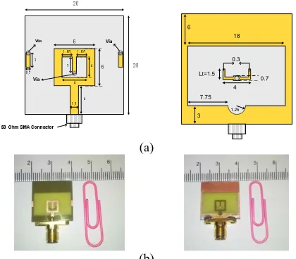
The geometry of the proposed antenna is illustrated in Figure 1(a). The fabricated prototype is also shown inFigure 1(b).
18 6
Lt=1.5
4
3 7.75
1.25
0.3
0.7
(a)
(b)
Figure 1. (a) Configuration of the proposed antenna and (b)
fabricated antenna.
The antenna is printed on a 20 × 20 mm2 FR4 substrate
with permittivity of 4.4, loss tangent of 0.002 and thickness of 0.8 mm. A 50 Ω microstrip feed line with dimensions of 4 × 1.5 mm2 is adopted to feed a 6 × 6
mm2 square radiating patch. Also, a semi-circle slot
with the radius of 1.25 mm is cut from the antenna ground plane on the back side of the substrate to improve impedance matching properties. In the sequel, with the aim of filtering the interfering bands with UWB frequency range, an inverted T-shaped element is deployed to filter 5-6 GHz (WLAN) from UWB. As it is seen in Figure 1, the inverted T-shaped element is divided into two parts. One part is on the front side of the substrate while the other is located on the back side of the substrate. The two parts are connected to each other using a via with radius of 0.35 mm. Moreover, two rectangular stubs with dimensions of 3 × 0.7 mm2
are placed on both sides of the radiating patch to subtract the frequency band of 3-4 GHz (WiMAX) from UWB. Rectangular stubs are connected to the ground plane on the back side of the substrate with two vias with radius of 0.35 mm. As it will be shown in the next sections, at the central frequencies of the notched bands (3.5 GHz and 5.5 GHz), the surface current on these elements would flow in the opposite direction of the main radiating current. Hence, the filtering mechanism is completed and the desired notched bands are achieved.
2. 1. Antenna Design Steps To accurately investigate the antenna performance, the design procedure is divided into four steps in Figure 2. As it is illustrated in this figure, Ant. I consists of a simple square radiating patch along with a ground plane on back side of the substrate. A wide square slot is also made on the ground plane. In Ant. II, a semi-circle slot is cut from the ground plane to enhance the impedance bandwidth. In the following, to realize the filtering mechanism, an inverted T-shaped stub is added resulting in Ant. III with the purpose of WLAN rejection. Eventually, in Ant. IV two rectangular stubs are deployed to filter WiMAX from UWB. The rectangular stubs are also connected to the backside of the substrate with two vias. The proposed strucures are simulated using Ansoft High Frequency Simulator (HFSS) where S11 curves are extracted for them in
and 5-6 GHz WLAN frequency band is filtered. Finally in Ant. IV, in addition to the filtering of WLAN, WiMAX rejection is also realized through two via-fed rectangular stubs. With respect to the simulated results in Figure 3, the final structure operates over the frequency range of 2.9-16 GHz and filters 3-4 GHz and 5-6 GHz. Surface current distribution at the central frequencies of the notched bands (3.5 GHz and 5.5 GHz) are shown in Figure 4. It is clearly seen that at the central notched frequencies, the current on inverted T-shaped element flows in opposite directions with respect to the radiating patch. It is the case for the two rectangular stubs with respect to the ground plane too. This is the main cause of filtering mechanism realization.
(d) (c)
(b)
(a)
Figure 2. (a) Ant. I, (b) Ant. II, (c) Ant. III and (d) Ant. IV.
Figure 3. S11 curves for the step-by-step antennas
(a) (b)
Figure 4. (a) Surface current distribution on the inverted
T-shaped element and (b) surface current distribution on the rectangular elements.
3. RESULTS AND DISCUSSION
The proposed antenna has been fabricated and then measured results are analysed. Figure 5 shows the simulated and measured S11 curves. As it is seen, close
agreement is obtained between the simulated and measured results and the slight difference is due to the fabrication tolerance and soldering effects. According to the measured results, UWB antenna operates over 3.2-15.3 GHz. After the realization of the band nocthed antenna, the frequency band of 2.9-16 GHz is covered except for two notches at 3-4 GHz and 5-6 GHz. The measured S11 bandwidth is slightly wider than the
simulated results specially at higher frequencies.
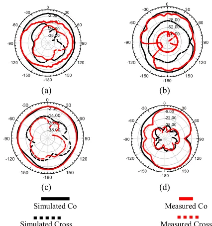
Figure 6 demonestrates the peak gain for both the UWB antenna and band notched antennas. As indicated in Figure 6, a nearly constant and acceptable gain is obtained for the two antennas. Due to the notches at 3-4 GHz and 5-6 GHz, sharp reductions in gain values are remarkable at these frequencies. This decline to negative values in the rejected bands confirms the weak performance of the antenna which is due to the overcoming of the interference of WiMAX and WLAN with UWB. The other important studied parameter is the group delay. In this case, the simulated and measured group delay curves are plotted in Figure 7. Obtained results approve a stable group delay in 2-16 GHz, except for 3-4 GHz and 5-6 GHz where sharp discontinuieties are created because of the notched bands. In addition, simulated and measured radiation patterns at 7 GHz and 12 GHz are shown in Figure 8. It can be observed that the obtained simulated results from HFSS and the results provided in antenna measurement chamber are in agreement with each other. Omnidirectional radiation pattern and low cross polarization level ensures the suitable performance of the proposed antenna.
4. ANALYTICAL HIERARCHY PROCESS (AHP) TO COMPARE THE PERFORMANCE OF THE PRESENTED UWB ANTENNA WITH SOME OF THE PREVIOUSLY DESIGNED UWB STRUCTURES
This section compares the proposed UWB antenna with some previous designs. UWB antennas in other works [13-15] are selected to be compared with the present work. Table 1 summerizes the charateristics of the foregoing structures. According to the data provided in Table 1, antennas defind in leterature [13]; in other literature widest bandwidth [14] have been reported respectively. Furthermore, the least gain vaiation in 2 dBi corresponds to the antenna in this work. Also, it is worth noting that the proposed antenna occupies less area than the others.In order to achieve a well-organized 2 3 4 5 6 7 8 9 10 11 12 13 14 15 16 17 18
-50 -40 -30 -20 -10 0 10
Frequency(GHz) S 11
(d
B)
Ant. I Ant. II Ant. III
comparison between the antenna structures and select the most suitable design, a comprehensive framework is needed to take into account all the operational features such as size, gain variation and bandwidth concurrently. AHP as one of the well-known MADM techniques have been proved to be very effective in such cases where there are more than one factor influencing the final decision.To apply the AHP technique to a certain problem, first, hierarchy schematic of the problem is to be clarified.
Figure 5. Simulated and measured S11 curves for the UWB
and band notched antenna.
Figure 6. Peak gain of the proposed UWB and band notched
antenna.
Figure 7. Simulated and measured group delay of the antenna
(a) (b)
(c) (d)
Simulated Co Measured Co
Simulated Cross Measured Cross
Figure 8. (a) H-plane (xz plane) pattern at 7 GHz, (b) E-plane
(yz plane) pattern at 7 GHz, (c) H-plane (xz plane) pattern at 12 GHz and (d) E-plane (yz plane) pattern at 12 GHz.
TABLE 1. Summary of the characteristics of the proposed
antenna and some previous designs.
Antenna Bandwidth (%) Gain variation (dBi) (mmSize 3)
Antenna in this
work 131 2 320
Antenna in [15] 122 3.9 600.25
Antenna in [14] 129 3.31 1554.3
Antenna in [13] 150 1.6 640
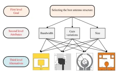
The hierarchy schematic consists of three levels encompassing goal, attributes and alternatives respectively. Goal is the purpose of the comparison in the investigated problem. Attributes are the most influencial parameters influencing the overall performance of the possible alternatives, and the alternatives are the candidates that are being compared. The hierarchy schematic for the antenna selection problem, interrogated herein, is illustrated in Figure 9.
“Selecting the best antenna structure” is the envisaged goal persued in the comparison. The surveyed antenna in this work as well as the antennas in other works[13-15] are the considered alternatives that are compared regarding size, bandwidth and gain variation.To make use of AHP method, a comprehensive utility function is defined based on Simple Additive Weighted (SAW) method. In this way, a utility value is assigned for each of the attributes namely USize, UBandwidth, and UGain-variation
for all of the considered alternatives. The assignment of utility values for attributes is based on the expert knowledge on a specific problem.
2 3 4 5 6 7 8 9 10 11 12 13 14 15 16 17 -30 -25 -20 -15 -10 -5 0 5 Frequency(GHz) S 11 (d B)
Simulated (UWB antenna) Simulated (band notched antenna) Measured (band notched antenna)
2 3 4 5 6 7 8 9 10 11 12 13 14 15 16 17 -8 -6 -4 -2 0 2 4 6 Frequency(GHz) Ga in (d B i)
band notched antenna UWB antenna
2 3 4 5 6 7 8 9 10 11 12 13 14 15 16 17 -1
-0.5 0 0.5
Figure 9. Analytical hierarchy schematic of the antenna selection problem.
Figure 10. Utility function values for the four antennas in
different cases for weight assignment.
TABLE 2. Considered cases for weight assignments for the
different attributes.
Cases WBandwidth WGain variations WSize
Case 1 0.33 0.33 0.33
Case 2 0.5 0.25 0.25
Case 3 0.25 0.5 0.25
Cae 4 0.25 0.25 0.5
TABLE 3. Utility values for the investigated antennas in four
cases for weight assignments.
Cases Antenna in
this work
Antenna in [15]
Antenna in [14]
Antenna in [13]
Case 1 0.316 0.207 0.184 0.293
Case 2 0.297 0.214 0.200 0.289
Case 3 0.312 0.194 0.183 0.311
Case4 0.342 0.214 0.166 0.277
For instance, in the case of analysing the suitability of an antenna, having small size, large bandwidth and low gain variations are recognized as desirable. With the aim of tackling the complexity of calculations, a normalizing system is utilized for utility value assignment. Regarding this issue, antenna having the lowest gain variations, gets the most value of unity and the antenna with the largest varation in gain values has
the minimum share of unity. The proposed utility fucntion for assessing the aforementioned antennas is introduced:
. ( )
. ( )
. ( )
Antenna j Bandwidth Bandwidth Gain var iation Gain variation Size Size
U W U Antenna j
W U Antenna j
W U Antenna j
= + +
(1)
where WBandwidth, WGain-variation, and WSize are the weight
values given to the bandwidth, gain variation, and size of the antenna, respectively. Weight allocation is done based on the importance degree of each attribute keeping their summation equal to one. For instance, for the applications where large bandwidth is a crucial parameter and size or gain variation are less important than bandwidth, the attribute of bandwidth gets higher value of weight than the others. The Expert Choice software [16] is used to implement the AHP technique encompassing four different cases as shown in Table 2. The obtained utility values for the investigated antennas in each of the foregoing cases is reported in Table 3. It can be observed that in case 1, where bandwidth, gain variation and size have the same degree of importance, the proposed antenna in this work shows a higher utility value based on Equation (1). Also, in cases 2, 3, and 4, where bandwidth, gain variations and size are respectively twice impotant than the other attributes, the same conclusion is infered. The obtained utility values in different cases are plotted in Figure 10 which provides a wise comparison between candidate antennas in different cases. This figure demonstrates the priority of each antenna to be applied in different circumastances. Also, it could be utilized to provide a comprehensive sensitivity analysis to reach the most suitable antenna considering all attributes. Based on the discussion above, the presented methodology provides a suitable tool to make decisions on selecting antenna strctures for specific applications.
5. CONCLUDING REMARKS
This paper targeted to present an efficient microstrip-fed antenna with salient features. The basic UWB antenna included a simple square radiating patch, a ground plane with a wide slot on the back side of the substrate as well as a semi-circle shaped slot behind the radiating patch. It was shown that by embedding a partially via-fed inverted T-shaped stub, it would be possible to realize the band notched configuration. Also, a new path for surface currents has been realized by the inclusion of this element which resulted in rejection of WLAN frequency band. Likewise, by implementing two rectangular via-fed stubs in the antenna body, notching the WiMAX range has been fulfiled. The UWB antenna is recognized to be capable of operating in 3.2-15.3 GHz and the resultant band stop antenna would cover 0
0.1 0.2 0.3 0.4
Case 1 Case 2 Case 3 Case 4
the frequency range of 2.9-16 GHz while rejecting 3-4 GHz and 5-6 GHz. A more precise evaluation on the performance of the proposed antenna has been executed by a novel framework based on the AHP methodology. The proposed framework validated the good performance of the surveyed antenna regarding wide bandwidth, good filtering properties, acceptable gain and radiation properties and a more compact and simple structure. The proposed methodology would help the relevant experts to make the most suitable decisions regarding antennas selection for specific applications.
6. ACKNOWLEDGMENT
This work was supported by a research grant provided from Urmia Branch, Islamic Azad University which is gratefully acknowledged.
7. REFERENCES
1. Sim, C., Chung, W.-T. and Lee, C.-H., "Compact slot antenna for uwb applications", Antennas and Wireless Propagation
Letters, IEEE, Vol. 9, (2010), 63-66.
2. Ojaroudi, M., Bashiri, S., Ojaroudi, N. and Partovi, M., "Octave-band, multi-resonance cpw-fed small slot antenna for uwb applications", Electronics Letters, Vol. 48, No. 16, (2012), 980-982.
3. Zhong, S.-S., Liang, X.-L. and Wang, W., "Compact elliptical monopole antenna with impedance bandwidth in excess of 21: 1", Antennas and Propagation, IEEE Transactions on, Vol. 55, No. 11, (2007), 3082-3085.
4. Paran, K. and Abolghasemi, A., "A novel volcano smoke antenna with optimal shape", Parameters, Vol. 9, (2012), 12. 5. Fakharian, M., Rezaei, P., Azadi, A. and Dadras, M., "A
capacitive fed microstrip patch antenna with air gap for
wideband applications", International Journal of Engineering, Vol. 27, No. 5, (2014).
6. Garg, R.R., "Antenna miniaturization using fractals (research note)", International Journal of Engineering-Transactions C:
Aspects, Vol. 25, No. 1, (2012), 39.
7. Xu, J., Shen, D., Zhang, X. and Wu, K., "A compact disc ultrawideband (uwb) antenna with quintuple band rejections",
Antennas and Wireless Propagation Letters, IEEE, Vol. 11,
(2012), 1517-1520.
8. Samadi Taheri, M.M., Hassani, H.R. and Nezhad, S.M.A., "Uwb printed slot antenna with bluetooth and dual notch bands",
Antennas and Wireless Propagation Letters, IEEE, Vol. 10,
(2011), 255-258.
9. Emadian, S.R., Ghobadi, C., Nourinia, J., Mirmozafari, M. and Pourahmadazar, J., "Bandwidth enhancement of cpw-fed circle-like slot antenna with dual band-notched characteristic",
Antennas and Wireless Propagation Letters, IEEE, Vol. 11,
(2012), 543-546.
10. Majidzadeh, M., Ghobadi, C. and Urmia, I., "A novel uwb cpw-fed ring-shaped antenna with band-notched characteristics", Turkish Journal of Electrical Engineering and Computer
Sciences, Vol. 21, No. 6, (2013), 1595-1602.
11. Ryu, K.S. and Kishk, A.A., "Uwb antenna with single or dual band-notches for lower wlan band and upper wlan band",
Antennas and Propagation, IEEE Transactions on, Vol. 57,
No. 12, (2009), 3942-3950.
12. Liao, X.-J., Yang, H.-C., Han, N. and Li, Y., "Uwb antenna with dual narrow band notches for lower and upper wlan bands",
Electronics Letters, Vol. 46, No. 24, (2010), 1593-1594.
13. Majidzadeh, M., Ghobadi, C. and Nourinia, J., "Compact cpw-fed circular patch antenna for uwb applications", Journal of
Communication Engineering, Vol. 2, (2013), 63-72
14. Chen, M.-E. and Wang, J.-H., "Cpw-fed crescent patch antenna for uwb applications", Electronics letters, Vol. 44, No. 10, (2008), 613-614.
15. Liu, W., Yin, Y., Xu, W. and Zuo, S., "Compact open-slot antenna with bandwidth enhancement", Antennas and Wireless
Propagation Letters, IEEE, Vol. 10, No., (2011), 850-853.
16. Lakrad, F. and Belhaq, M., "Suppression of pull-in instability in mems using a high-frequency actuation", Communications in
Nonlinear Science and Numerical Simulation, Vol. 15, No.
Multi Attribute Analysisofa Novel Compact UWB Antennawith Via-fed Elementsfor
Dual Band Notch Function
Ch. Ghobadi, M. Majidzadeh
Department of Electrical Engineering, Urmia Branch, Islamic Azad University, Urmia, Iran
P A P E R I N F O
Paper history:
Received 11 February 2014 Accepted in revised form 22 May 2014
Keywords:
Analytical Hierarchy Process Dual Band-notch
Expert Choice Software UWB Antenna Via-fed Elements
هﺪﯿﮑﭼ
ﺖﺳاهﺪﺷﻪﺋاراﯽﺴﻧﺎﮐﺮﻓچﺎﻧودياراﺪﮑﭼﻮﮐﭗﯾﺮﺘﺳاوﺮﮑﯿﻣﻦﺘﻧآﮏﯾزايﺪﯾﺪﺟرﺎﺘﺧﺎﺳﻪﻟﺎﻘﻣﻦﯾارد
.
ﻪﯾﺎﭘﻦﺘﻧآﮏﯾاﺪﺘﺑارد
ﺖﺳاهﺪﻣآدﻮﺟوﻪﺑﻪﯾﺎﭘرﺎﺘﺧﺎﺳزاﯽﺴﻧﺎﮐﺮﻓچﺎﻧيارادﻦﺘﻧآرﺎﺘﺧﺎﺳﺲﭙﺳوهﺪﺷﻪﺋاراﺪﻧﺎﺑﻦﻬﭘاﺮﻓﯽﺴﻧﺎﮐﺮﻓهزﻮﺣياﺮﺑ
.
هﺪﺷﻞﯿﮑﺸﺗﻪﯾﻻﺮﯾزﺖﺸﭘردتﻼﺳايارادﻦﯿﻣزﻪﺤﻔﺻﮏﯾوهدﺎﺳﯽﻌﺑﺮﻣﯽﻌﺸﻌﺸﺗﭻﭘﮏﯾزاﺪﻧﺎﺑﻦﻬﭘاﺮﻓﻦﺘﻧآﻪﯾﺎﭘرﺎﺘﺧﺎﺳ
ﺖﺳا
.
هﺮﯾادﻢﯿﻧفﺎﮑﺷﮏﯾ
ﻖﯿﺒﻄﺗدﻮﺒﻬﺑﺚﻋﺎﺑﻪﮐﺖﺳاهﺪﺷهﺪﯾﺮﺑﻦﯿﻣزﻪﺤﻔﺻزاﯽﻌﺸﻌﺸﺗﭻﭘﯽﻨﯿﯾﺎﭘﻪﺒﻟﺖﺸﭘردﺖﺳرديا
ﯽﻣﯽﺴﻧاﺪﭙﻣا
دﻮﺷ
.
ندﺮﮐﺮﺘﻠﯿﻓفﺪﻫﺎﺑﺲﭙﺳ
ﯽﺴﻧﺎﮐﺮﻓيﺎﻫﺪﻧﺎﺑ
WiMAX
و
WLAN
ﮏﯾ،ﺪﻧﺎﺑﻦﻬﭘاﺮﻓﯽﺴﻧﺎﮐﺮﻓﺪﻧﺎﺑزا
نﺎﻤﻟا
T
ﺎﺑهﺪﻧﻮﺷﻪﯾﺬﻐﺗﯽﻠﯿﻄﺘﺴﻣيوزﺎﺑودوﻪﻧوراو
via
هﺪﺷيزﺎﺳﺎﺟﻦﺘﻧآرﺎﺘﺧﺎﺳرد
ﺪﻧا
.
ﻪﯾﻻﺮﯾزيورﺮﺑهﺪﺷﻪﺋاراﻦﺘﻧآ
FR4
هزاﺪﻧاﻪﺑ
0.8
×
20
×
20
ﺪﻧﺎﺑيﺎﻨﻬﭘوﺖﺳاهﺪﺷپﺎﭼﺐﻌﮑﻣﺮﺘﻤﯿﻠﯿﻣ
16 -2.9
ﺮﺘﻠﯿﻓﯽﺴﻧﺎﮐﺮﻓيﺎﻫﺪﻧﺎﺑﺰﺟﻪﺑﺰﺗﺮﻫﺎﮕﯿﮔ
هﺪﺷ
WiMAX
و
WLAN
ﯽﻣﺶﺷﻮﭘار
ﺪﻫد
.
يﺎﻫرﺎﺘﺧﺎﺳزاﯽﺧﺮﺑﺎﺑﻪﻟﺎﻘﻣﻦﯾاردهﺪﺷﻪﺋاراﻦﺘﻧآدﺮﮑﻠﻤﻋﻪﺴﯾﺎﻘﻣياﺮﺑ
ﯽﺒﺗاﺮﻣﻪﻠﺴﻠﺳﻞﯿﻠﺤﺗﺪﻨﯾآﺮﻓﻪﯾﺎﭘﺮﺑﺪﯾﺪﺟبﻮﭼرﺎﭼﮏﯾﯽﻠﺒﻗهﺪﺷﻪﺋارا
(AHP)
ﺖﺳاهﺪﺷﻪﺋارا
.
شورزاهدﺎﻔﺘﺳاﺎﺑ
AHP
ﯽﻣ
ﻧآناﻮﺗ
ﻦﺘ
ﻪﺒﻨﺟﻪﺑﺖﺒﺴﻧنﺎﻣﺰﻤﻫرﻮﻃﻪﺑارﺮﻈﻧدرﻮﻣيﺎﻫ
ﻪﺴﯾﺎﻘﻣﺐﯿﺗﺮﺗﻦﯾاﻪﺑودﺮﮐﻪﺴﯾﺎﻘﻣﻒﻠﺘﺨﻣيدﺮﮑﻠﻤﻋيﺎﻫ
يا
دادمﺎﺠﻧاﻊﻣﺎﺟوﻞﻣﺎﮐ
.
ﺪﺘﻣلﺎﻤﻋاياﺮﺑ
AHP
مﺮﻧزا
راﺰﻓا
Expert Choice
ﺖﺳاهﺪﺷهدﺎﻔﺘﺳا
.
doi: 10.5829/idosi.ije.2014.27.10a.10
![Table 1, antennas defind in leterature [13]; in other](https://thumb-us.123doks.com/thumbv2/123dok_us/230669.2017637/3.595.65.261.605.703/table-antennas-defind-leterature.webp)