ORIGINAL ARTICLE
Neural Network-Based Adaptive Motion
Control for a Mobile Robot with Unknown
Longitudinal Slipping
Gang Wang
*, Xiaoping Liu, Yunlong Zhao and Song Han
Abstract
When the mobile robot performs certain motion tasks in complex environment, wheel slipping inevitably occurs due to the wet or icy road and other reasons, thus directly influences the motion control accuracy. To address unknown wheel longitudinal slipping problem for mobile robot, a RBF neural network approach based on whole model approximation is presented. The real-time data acquisition of inertial measure unit (IMU), encoders and other sensors is employed to get the mobile robot’s position and orientation in the movement, which is applied to compensate the unknown bounds of the longitudinal slipping using the adaptive technique. Both the simulation and experimental results prove that the control scheme possesses good practical performance and realize the motion control with unknown longitudinal slipping.
Keywords: Mobile robot, Longitudinal slipping, RBF neural network, Adaptive control
© The Author(s) 2019. This article is distributed under the terms of the Creative Commons Attribution 4.0 International License (http://creat iveco mmons .org/licen ses/by/4.0/), which permits unrestricted use, distribution, and reproduction in any medium, provided you give appropriate credit to the original author(s) and the source, provide a link to the Creative Commons license, and indicate if changes were made.
1 Introduction
With the development of robotic applications, higher requirements have been presented for the motion con-trol problem of mobile robots. Most researches shown the control schemes for mobile robots are based on the assumption that the wheels roll without slipping and
skidding [1–3]. In previous work, many intelligent
con-trol technologies, such as kinematic∕torque concon-trol
method using backstepping [4], a modified
input–out-put linearization method [5], a data-based tracking
con-trol [6, 7], a sliding-mode based tracking algorithms
[8–10], neural networks tracking control method [11,
12], extended state observer based nonlinear
track-ing and obstacle avoidance control method [13],
distur-bance observer-based robust trajectory tracking method
[14], based on this assumption have been proposed for
the robotics research. However, when the mobile robot performs certain motion tasks in complex environment, such as in wet or icy ground, high velocity starting and stopping and so on, these assumptions cannot be met
due to slipping effect. All of these will cause the accumu-lative error of pose compared with conventional mobile
robots [15] and certainly do deteriorate motion accuracy
of mobile robot.
Consequently, approaches form control perspective have been receiving increased attention for the mobile robot in presence of slipping. Many researches have mentioned previously regarding the slipping
phenom-enon for the mobile robots. In Ref. [16], Dixon et al. [17]
on the basis of their previous work addressed the skid-ding for mobile robots by designing robust tracking and regulation controllers at the kinematic level. Relying on kinematic-global positioning system and other sensors to collect the robot’s information, such as posture, veloci-ties, Chang Boon Low et al. developed a GPS-based
con-troller to realize the path following [18, 19]. In Ref. [20],
considering the disturbing influence of skid-slip effects, the Vector Field Orientation (VFO) feedback approach is presented to perform the trajectory tracking tasks. For mobile robots in presence of slip conditions,
Gonza-lez et al. [21] proposed an adaptive control law together
with an LMI-Based approach, which guarantee the sta-bility and asymptotical convergence subject to both con-straints and varying dynamics. Aimed at the trajectory
Open Access
*Correspondence: [email protected]
tracking subject to unknown wheels’ slipping, Cui et al.
[22] addressed the unknown skidding for mobile robots
by designing adaptive unscented Kalman filter scheme. Though kinematic modeling with wheel slipping phe-nomena gives a theoretical possibility of obtaining good performance of the control action, the kinematics model is only taken position and velocity into account, and without model uncertainties, unmodelled or unstruc-tured disturbances, nonlinear friction and other factors. For that reason, it is necessary to study the motion con-trol problem from the viewpoint of dynamics.
For the wheeled mobile robot under unknown skidding
and slipping conditions, one previous study [23]
pre-sented an adaptive tracking control scheme with torque saturation.
Regarding skidding and slipping as disturbances, Kang
et al. [24] proposed a robust tracking approach using a
generalized extended state observer at kinematic and
dynamic level. Later in their work, Kang et al. [25]
pro-poses a robust tracking controller based on the fuzzy disturbance observer for a WMR with unknown
skid-ding and slipping. Subject to Wheel Slip, Tian et al. [26]
developed a time-invariant discontinuous feedback law is to asymptotically stabilize the robot system. In order to perform trajectory tracking under the longitudinal slip
condition, Gao et al. [27] proposed an improved adaptive
controller together with a neural network learning proce-dure. When existing the skidding, slipping and input
dis-turbance, Chen [28] proposed a robust tracking control
scheme based on the disturbance observer for wheeled
mobile robots. In Ref. [29], a reinforcement
learning-based adaptive neural tracking algorithm is proposed for the nonlinear discrete-time dynamic system of the WMR with skidding and slipping. From all the research above, we can find that most of the work focus on the control scheme design, which is only validated by simulation, lacking of experimental validation.
In the practical applications of our mobile robot, as longitudinal slipping is a more common phenom-enon, this paper focus on the motion control research for mobile robots with unknown longitudinal slipping. Accordingly, based on the dynamic model, a neural net-work approach based on whole model approximation for the motion control of mobile robots under unknown lon-gitudinal slipping occurrence is proposed. The unknown bounds of the longitudinal slipping are compensated by the adaptive technique. The proposed control system can achieve the accurate motion control of the mobile robot.
The rest of this paper is organized as follows. Kinemat-ics and dynamKinemat-ics of a mobile robot with longitudinal
slip-ping are derived mathematically in Section 2. Section 3
introduce the model of control system. In Section 4,
simu-lations on motion control problems for a wheeled mobile
robot subject to longitudinal slipping are carried out. Three
groups of experiments are presented in Section 5, to
vali-date the applicability of the proposed control scheme to real system, showing the robustness property of the
pro-posed scheme. Section 6 concludes this paper.
2 Problem Formulation
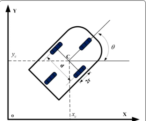
Before discussing control strategy, a typical example of a differentially driven mobile robot used for the research of trajectory tracking is considered in this paper. The mobile
robot platform under study is depicted in Figure 1, which
composes of a vehicle with two driving wheels mounted on the same axis, whereas both a front and a rear free wheel only used for supporting the robot platform and with-out guide effect. The motion of mobile robot is achieved by two motors providing the necessary torques for the driving wheels, although both two motors are completely independent in the whole system, each motor has almost the same characteristics, such as position, velocity, accel-eration, force response, friction model and other nonlinear phenomenon.
The dynamic model of the mobile robot can be expressed
in the Lagrange form [2]
where q=
x y θT is the location of the mobile robot
in the inertial Cartesian frame, (x, y) and θ represent the
position and orientation respectively. M(q)=
m 0 0
0 m 0 0 0 Ic
is a symmetric, positive definite inertia matrix,
V(q,q˙)=0 is the centripetal and coriolis matrix, G(q) is
the gravity vector, τd denotes bounded unknown
(1) M(q)q¨+V(q,q)˙ q˙+G(q)+τd=B(q)τ −AT(q),
disturbances including unstructured unmodelled
dynam-ics, B(q)= 1r
cosθ cosθ sinθ −d 2 sinθ d 2
is the input transformation
matrix, τ =
τl τr
is the control input torque supplied by
two motors, AT(q)=
−sinθ cosθ 0
is the matrix associated with the constraints, and
= −m ˙
xccosθ+ ˙ycsinθ ˙
θ is the vector of constraint
forces. In the above formula, m is the mass of mobile
robot platform, Ic is its moment of inertia, r is the wheel
radius, d is the distance between the two driving wheels,
τi is the wheel torque for the ith wheel. As the mobile
robot being studied is working on a level surface with no
slope, here the gravitational vector G(q) tends to zero.
The nominal kinematic model in the ideal case can be formulated as follows:
For conciseness, we denote
The subscript number l and r represent the left and right
drive wheel respectively, v=
vl vr T
is the correspond-ing drivcorrespond-ing velocity.
When longitudinal slipping occurs during the
move-ment, the slip ratios is defined as follows [21]:
where sl and sr are the slip ratios of the left and right
wheels, v¯l and v¯r are the corresponding current
veloc-ity caused by longitudinal slipping, respectively. There are two points worth noting in relation to the longitudi-nal slip. Firstly, if the longitudilongitudi-nal slippage do not hap-pen, the current driving velocity is equal to the reference
velocity with sl=sr =0 . Secondly, in any case the slip
ratios sr =1 and sl =1 , assuming that sr =sl=1 that
means wheel totally slipping and leads the mobile robot in uncontrolled state, therefore this situation is generally neglected.
The current velocity of the left and right drive wheel under the longitudinal slipping conditions is as follows:
(2) ˙ q= ˙ xc ˙ yc ˙ θ = cosθ 2 cosθ 2 sinθ 2 −1 d sinθ 2 1 d � vl vr � . (3) ˙
q=S(θ )v.
(4)
sl= vl−¯vlvl, sr = vrvr−¯vr,
(5) vl vr = 1 1−sl 0 0 1−sr1
¯ vl ¯ vr .
Substituting Eq. (5) into Eq. (3) yields, the
kinemat-ics model in presence of longitudinal slipping is shown as follows
where
¯ v=
¯ vl v¯r
T
are the current velocity of the two wheels, which can be real-time measured by encoders.
Substituting Eq. (6) into Eq. (1) yields, we can obtain the
dynamic form of the mobile robot subject to longitudinal slipping as
where
¯
B(¯v)= ¯STB . We observe that when longitudinal slipping
impact are considered in the dynamic model, it becomes more complicated.
3 Mathematical Model of Control System for Mobile Robot
The ultimate goal of motion control considering the longi-tudinal slipping is to control the torque so that the robot can follow preconcerted trajectory. In the inertial coordinate
system, given a reference trajectory qr(t)=
xr yr θr
T
and a current trajectory q(t)=
x y θT
, the tracking error is expressed as
The derivative of e(t) with respect to t
The auxiliary velocity is defined as [30]
where k1, k2, k3 are design parameters.
The derivation of ξc can be written as
(6) ˙
q= ¯S(θ,sl,sr)¯v,
¯
S(θ,sl,sr)=
cosθ 2(1−sl)
cosθ 2(1−sr) sinθ
2(1−sl)(1−sl)
− 1
d(1−sl)
sinθ 2(1−sr)
1 d(1−sr)
, (7) ¯
M(¯v)v˙¯+ ¯V(¯v)v¯+ ¯τd = ¯B(v)¯ τ¯,
¯
M(v)= ¯STMS,¯ V¯(v)= ¯STMS˙¯+VS¯=0, τ¯ d= ¯STτ
d,
(8) e(t)=
cosθ sinθ 0
−sinθ cosθ 0
0 0 1
xr−x yr−y θr−θ
. (9) ˙ e(t)=
vrcosθr−v+xeθ˙
vrsinθr+xeθ˙
wr− ˙θ
.
(10) ξc=
vc wc =
vrcosθe+k1xe wr+k2vrye+k3vrsinθe
And assuming that the linear and angular reference
velocities are constant, we obtain [4]
To design the control input and follow the desired velocity, we introduce the auxiliary velocity tracking error
In this part, we adopt tracking error e¯ as the design
cri-teria for neural adaptive controller. The filtered tracking
error [31] is
where Λ=ΛT>0. Differentiating the above formula,
the dynamics can be expressed in the filtered tracking error
where the nonlinear function is
and, for instance
In this part a computed torque method is developed for trajectory tracking. Define a control input torque as
where gˆ is the estimate of g(x) and Kv=KvT>0 is the
gain matrix. Substituting Eq. (17) into Eq. (15) yields, we
can get
where the functional estimation error is expressed as
˜
g =g− ¯B(v)¯ gˆ , ζo = ˜g+ ¯τd.
Due to RBF neural network has a good performance in learning and approximating nonlinear functions, hence in this paper to eliminate these uncertainties, the RBF is applied into the mobile robot system for approximating
function g(x):
(11) ˙
ξc= ˙ vc ˙ wc = ˙
vrcosθe ˙
wr+k2v˙rye + k1 0 0
k2vr
−vrsinθe
k3vrcosθe
˙ e.
(12) ˙
ξc= ˙ vc ˙ wc = k1 0 0 k2vr
−vrsinθe
k3vrcosθe
˙ e.
(13) e(t)=ξ−ξc.
(14)
r= ˙¯e+Λe,¯
(15) ¯
M(v)˙r= − ¯V(v)r+g(x)+ ¯τd− ¯B(¯v)τ¯,
g(x)= ¯M(v)(v˙c+Λ˙e)+ ¯V (v)(vc+Λe)vc+ ¯G(v)
(16)
x= ¯
eT e˙¯T vrT v˙Tr v¨Tr .
(17) ¯
τ =gˆ+Kvr,
(18) ¯
M(v)˙r= − ¯V(v)r+g(x)+ ¯τd− ¯B(¯v)gˆ+Kvr
= −¯
V(v)+KvB(¯¯ v)r+ζo,
ˆ
g(x)= ˆWTϕ(x),
where Wˆ is the current values of the neural network
weights provided by the tuning algorithm, W is ideal
weights.
Define the weight estimation errors as
here the ideal weights is to be known bounded under the assumptions, so that
With τ¯ defined in Eq. (17), the control input is
where ν is a function to be determined to provide
robust-ness in the face of the net reconstruction error ε. Then
substituting Eq. (14) into Eq. (13) yields,
where ζ1= ˆWTϕ(x)+(ε+ ¯τd)+ν.
The auxiliary signal
and the weight tuning is given as
where the constant matrix F=FT>0.
Define the Lyapunov function candidate
Differentiating yields
Substituting Eq. (20) into Eq. (22) yields,
Due to the skew symmetry property, we can get the second term zero and the third term is zero when
choos-ing W˙˜ = −FϕrT,
where
rT(ε+ ¯τd+ν)=rT(ε+ ¯τd)+rTν
=rT(ε+ ¯τd)− �r�(εN+bd)≤0.
˜
W =W − ˆW,
�W�F ≤Wmax.
(19) ¯
τ= ˆg(x)+Kvr−ν= ˆWTϕ(x)+Kvr−ν,
(20) ¯
M(v)˙r= −
Kv+ ¯V(v)
r+ ˆWTϕ(x)+(ε+ ¯τd)+ν
= −
Kv+ ¯V(v)
r+ζ1,
ν= −(εN +bd)sgn(r),
˙ˆ
W =FϕrT,
(21)
L= 1
2r
TM¯(v)r+ 1
2tr
˜
WTF−1W˜
.
(22)
˙
L=rTM¯(v)˙r+ 1
2r
TM˙¯(v)r +trW˜TF−1W˙˜ .
˙
L= −rTKvr+1
2r
TM(˙¯ v)−2V¯(v)r
+trW˜ TF−1W˙˜ +ϕrT+rT(ε+ ¯τd+ν).
˙
Finally, we get
˙
L≤0.
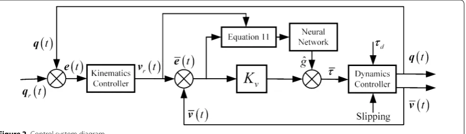
The control system diagram is shown in Figure 2.
4 Simulation Results
In this section, we perform representative simulations for the mobile robot platform subject to unknown lon-gitudinal slipping to demonstrate the validity of the pro-posed scheme. The propro-posed method was implemented in MATLAB/Simulink software. In addition, by utilizing the dynamic analysis software, we have the parameters
of our mobile robot shown in Table 1.
In the simulations, in order to eliminate the difference influence of the velocities of the two driving wheels, a liner reference trajectory is considered. Given the
refer-ence trajectory velocities v= [0.1sint, 0.1sint]T where
t∈[0‒50] s is the simulation time. Assume that the left
and right wheels’ longitudinal slipping described by
sl =0.2 sin(v¯l) and sr=0.2 sin(v¯r) . The control gains are
selected as:
Kv=
50 0 0 50
,
¯
F(v)¯ =0.02sgn(v),¯
¯
τd=0.2 sin(t) 0.2 sin(t)T.
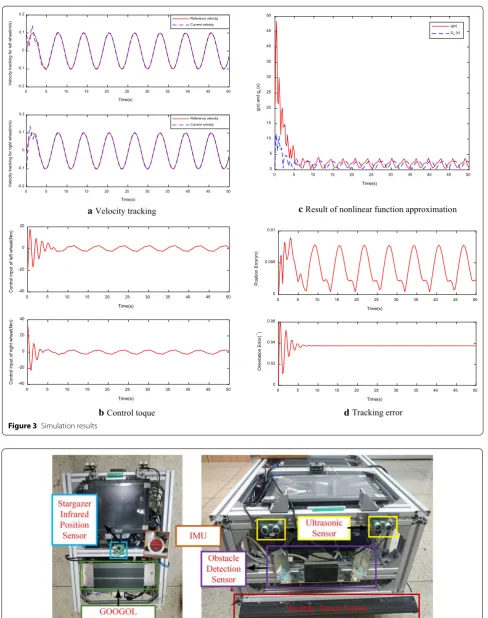
Under the wheel longitudinal slipping conditions,
Fig-ure 3 shows the performance of control scheme for the
mobile robot. The velocity tracking results of each driving
wheel in our method is shown in Figure 3(a), which traced
the reference signal rapidly and stably. Under the longitudi-nal slipping conditions, the corresponding torque on each
driving wheel is shown in Figure 3(b), showing that the
proposed method can perform well to adapt to the distur-bance phenomena of the longitudinal slipping. The reason for this is that the model-based adaptive law is employed to compensate the disturbances in the mobile robot systems. Furthermore, since RBF network have good approximate capability for the nonlinear function with enough precision, in this paper the neural network is employed to approxi-mate the non-linear component of the whole system, as
shown in Figure 3(c). Figure 3(d) gives the corresponding
position and orientation tracking errors in inertia coordi-nate, which indicates that this control algorithm can realize the good precision of position control and orientation con-trol in the motion with longitudinal slipping.
5 Experimental Verification
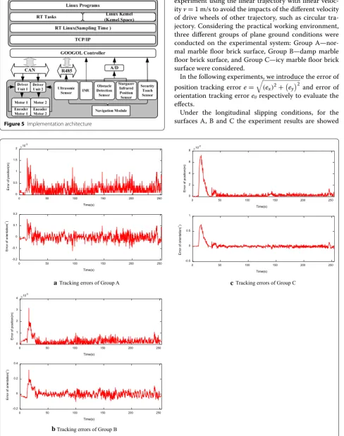
Besides the simulation, a verification platform has been set up to verify the above presented scheme and study fundamental problems in motion control process of mobile robot with longitudinal slipping, as displayed in
Figure 4. The experiment platform consists of two sets of
direct motor system with absolute rotary encoder, ultra-sonic sensor, IMU, obstacle detection sensor, stargazer infrared position sensor, security touch sensor. IMU equipped in the mobile robot platform is used to collect the robot’s current orientation information and the abso-lute rotary encoder to collect the current velocity. The parameters used in the experiment system are the same
with the one in simulation shown in Table 1. Under
RT-Linux operation system, C language has been adopted to
write all computations, as shown in Figure 5.
Figure 2 Control system diagram
Table 1 Parameters used in the simulation
Parameter Symbol Value Units
aVelocity tracking
0 5 10 15 20 25 30 35 40 45 50
Time(s)
-0.2 -0.1 0 0.1 0.2
Velocity tracking for left wheel(m/s)
Reference velocity Current velocity
0 5 10 15 20 25 30 35 40 45 50
Time(s)
-0.2 -0.1 0 0.1 0.2
Velocity tracking for right wheel(m/s)
Reference velocity Current velocity
bControl toque d
0 5 10 15 20 25 30 35 40 45 50
Time(s) -40
-20 0 20
Control input of left wheel(Nm)
0 5 10 15 20 25 30 35 40 45 50
Time(s) -40
-20 0 20 40
Control input of right wheel(Nm
)
cResult of nonlinear function approximation
Tracking error
0 5 10 15 20 25 30 35 40 45 50
Time(s) 0
5 10 15 20 25 30 35 40 45 50
g(x) and
gn
(x)
g(x) gn(x)
0 5 10 15 20 25 30 35 40 45 50
Time(s) 0
0.005 0.01
Position Error(m)
0 5 10 15 20 25 30 35 40 45 50
Time(s) 0
0.02 0.04 0.06
Orientation Error(
°)
Figure 3 Simulation results
In the experimental verifications, we conducted the experiment using the linear trajectory with linear
veloc-ity v= 1 m/s to avoid the impacts of the different velocity
of drive wheels of other trajectory, such as circular tra-jectory. Considering the practical working environment, three different groups of plane ground conditions were conducted on the experimental system: Group A—nor-mal marble floor brick surface, Group B—damp marble floor brick surface, and Group C—icy marble floor brick surface were considered.
In the following experiments, we introduce the error of
position tracking error e=
(ex)2+
ey2 and error of
orientation tracking error eθ respectively to evaluate the
effects.
Under the longitudinal slipping conditions, for the surfaces A, B and C the experiment results are showed
Figure 5 Implementation architecture
Tracking errors of Group A
Tracking errors of Group B
Tracking errors of Group C
0 50 100 150 200 250
Time(s) -0.2
-0.1 0 0.1 0.2
Error of orientation(
°)
0 50 100 150 200 250
Time(s) 0
0.5 1 1.5 2
Error of position(m)
10-3
0 50 100 150 200 250
Time(s) -0.2
0 0.2 0.4
Error of orientation
(
°)
0 50 100 150 200 250
Time(s) 0
1 2 3 4
Error of position(m)
0 50 100 150 200 250
Time(s) -0.5
0 0.5 1
Error of orientation
(
°)
0 50 100 150 200 250
Time(s) 0
2 4 6 8
Error of position(m
)
10-3
10-3
a
b
c
in Figure 6. For experiments of three groups, the linear trajectory tracking results between the Group B and the Group C presented a similar tendency under the same experimental conditions apart from the floor surface. A slightly worse result of the group C was illustrated in
Figure 6(c), where the more highly slippery surface
com-pared with the group B made that slipping phenomena more obvious, both the position error and orientation error of the group C presented a greater experimental
error than that of group B in Figure 6(b) when the mobile
robot suddenly changes the direction.
It is worth noting that a longer time for experiment group C is required for the mobile robot from the start-ing point to destination. The reason for this phenomenon is the fact that the longitudinal slipping as an external disturbance reduces the linear velocity, as a result the controllers must adjust the input to compensate this deviation caused by the longitudinal slipping.
Further-more, we may also see from Figure 6 that the
longitudi-nal slipping phenomena mainly occurs at the acceleration stage of the mobile robot. From the experiment results, we obtain that under different surface environment the method has certain practicality to the unknown longitu-dinal slipping and robustness, realizing adaptive tracking ability.
6 Conclusions
An adaptive motion control problem was formulated for the mobile robot under the longitudinal slipping condi-tion in this paper. To address the unknown longitudinal slipping, by utilizing the real-time multi-sensor data to get the position and orientation of the robot, an adaptive neural network approach based on whole model approxi-mation has been developed, to compensate the trajectory error caused by longitudinal slipping. Both the simula-tion and experimental results have been proved to be robust and adaptive to the environment with unknown longitudinal slipping in the practical application.
Authors’ Contributions
GW was in charge of the whole trial and wrote the manuscript; XL advised on how to write the manuscript during the whole preparation. YZ and SH assisted with sampling and laboratory analyses. All authors read and approved the final manuscript.
Authors’ Information
Gang Wang, born in 1981, is currently a Lecturer with Beijing University of Posts and Telecommunications, China. He received his Bachelor’s degree and Master’s degree from Shandong University of Science and Technology, China, in 2006 and 2009 respectively, and his Ph.D. degree from Beihang University, China, in 2016. His research interests include robot calibration and mobile robot navigation.
Xiaoping Liu, born in 1965, is currently a Professor with Beijing University of Posts and Telecommunications, China. He received his Bachelor’s degree, Master’s degree and Ph.D. degree from Tianjin University, China, in 1988, 1991,
1994, respectively. From 1998 to 1999, he was with University of Washington, USA. His research interests include robotics, fault diagnosis and detection.
Yunlong Zhao, born in 1990, is currently a PhD candidate with Automation School, Beijing University of Posts and Telecommunications, China. He received his Master’s degree from China University of Mining and Technology, Beijing, China, in 2016.
Song Han, born in 1991, is currently a PhD candidate with Automation School, Beijing University of Posts and Telecommunications, China. He received his Bach-elor’s degree from University of Science and Technology of China, China, in 2014. His research interests include robot calibration and mobile robot navigation.
Funding
Supported by Scientific and Innovation Research Funds for the Beijing Univer-sity of Posts and Telecommunications (Grant No. 2017RC22).
Competing Interests
The authors declare that they have no competing interests.
Received: 11 April 2018 Revised: 7 January 2019 Accepted: 1 July 2019
References
[1] Z P Jiangdagger, H Nijmeijer. Tracking control of mobile robots: A case study in backstepping. Automatica, 1997, 33(7): 1393–1399.
[2] J M Yang, J H Kim. Sliding mode control of trajectory tracking for non-holonomic wheeled mobile robots. IEEE Transactions on Robotics and Automation, 1999, 15(3): 578–587.
[3] H Yang, X Fan, P Shi, et al. Nonlinear control for tracking and obstacle avoidance of a wheeled mobile robot with nonholonomic constraint.
IEEE Transactions on Control Systems Technology, 2016, 24(2): 741–746. [4] R Fierro, F L Lewis. Control of a nonholonomic mobile robot:
Backstep-ping kinematics into dynamics. Proceedings of the 34th Conference on Decision & Control, New Orleans, 1995: 3805–3810.
[5] D H Kim, J H Oh. Tracking control of a two-wheeled mobile robot using input–output linearization. Control Engineering Practice Control, 1999, 7(3): 369–373.
[6] J Chen, W E Dixon, M Dawson, et al. Homography-based visual servo tracking control of a wheeled mobile robot. IEEE Transactions on Robotics, 2006, 22: 406–415.
[7] H Mirzaeinejad, A M Shafei. Modeling and trajectory tracking control of a two-wheeled mobile robot: Gibbs-Appell and prediction-based approaches. Robotica, 2018, 36(10): 1551–1570.
[8] J M Yang, J H Kim. Sliding mode control for trajectory tracking of nonho-lonomic wheeled mobile robots. IEEE Transactions on Robotics & Automa-tion, 1999, 15(3): 578–587.
[9] M Asif, M J Khan, N Cai. Adaptive sliding mode dynamic controller with integrator in the loop for nonholonomic wheeled mobile robot trajectory tracking. International Journal of Control, 2014, 87(5): 964–975.
[10] S Peng, W Shi. Adaptive fuzzy integral terminal sliding mode control of a nonholonomic wheeled mobile robot. Mathematical Problems in Engineering, 2017: 3671846:1–12.
[11] M Boukens, A Boukabou, M Chadli. Robust adaptive neural network-based trajectory tracking control approach for nonholonomic electrically driven mobile robots. Robotics & Autonomous Systems, 2017, 92: 30–40. [12] L Ding, S Li, Y J Liu, et al. Adaptive neural network-based tracking control
for full-state constrained wheeled mobile robotic system. IEEE Transac-tions on Systems Man & Cybernetics Systems, 2017, 47(8): 2410–2419. [13] H Yang, X Fan, P Shi, C C Hua. Nonlinear control for tracking and obstacle
avoidance of a wheeled mobile robot with nonholonomic constraint.
IEEE Transactions on Control Systems Technology, 2016, 24(2): 741–746. [14] D Huang, J Zhai, W Ai, et al. Disturbance observer-based robust control
[15] L Ding, H B Gao, Z Q Deng, et al. Experimental study and analysis on driving wheels’ performance for planetary exploration rovers moving in deformable soil. Journal of Terramechanics, 2011, 48: 27–45.
[16] W E Dixon, D M Dawson, E Zergeroglu. Robust control of a mobile robot system with kinematic disturbances. IEEE International Conference on Control Applications, 2000: 437–442.
[17] W Dixon, D M Dawson, E Zergeroglu. Nonlinear control of wheeled mobile robot. Lecture Notes in Control and Information Sciences. New York: Springer-Verlag, 2001.
[18] B L Chang, D Wang. GPS-based tracking control for a car-like wheeled mobile robot with skidding and slipping. IEEE/ASME Transactions on Mechatronics, 2008, 13(4): 480–484.
[19] C B Low, D Wang. GPS-based path following control for a car-like wheeled mobile robot with skidding and slipping. IEEE Transactions on Control Systems Technology, 2008, 16(2): 340–347.
[20] M Michalek, P Dutkiewicz, M Kielczewski, et al. Trajectory tracking for a mobile robot with skid-slip compensation in the vector-field-orientation control system. International Journal of Applied Mathematics & Computer Science, 2009, 19(4): 547–559.
[21] R Gonzalez, M Fiacchini, T Alamo, et al. Adaptive control for a mobile robot under slip conditions using an LMI-based approach. European Journal of Control, 2010, 16(2): 144–155.
[22] M Cui, D Sun, W Liu, et al. Adaptive tracking and obstacle avoidance control for mobile robots with unknown sliding. International Journal of Advanced Robotic Systems, 2012, 9: 1.
[23] S J Yoo. Adaptive tracking control for a class of wheeled mobile robots with unknown skidding and slipping. IET Control Theory & Applications, 2010, 4(10): 2109–2119.
[24] H S Kang, Y T Kim, C H Hyun, et al. Generalized extended state observer approach to robust tracking control for wheeled mobile robot with skid-ding and slipping. International Journal of Advanced Robotic Systems, 2013, 10: 463–474.
[25] H S Kang, C H Hyun, S Kim. Robust tracking control using fuzzy distur-bance observer for wheeled mobile robots with skidding and slipping.
International Journal of Advanced Robotic System, 2014, 11(1): 1–11. [26] Y Tian, N Sarkar. Control of a mobile robot subject to wheel slip. Journal of
Intelligent & Robotic Systems, 2014, 74: 915–929.
[27] H Gao, X Song, D Liang, et al. Adaptive motion control of wheeled mobile robot with unknown slippage. International Journal of Control, 2014, 87(8): 1513–1522.
[28] M Chen. Disturbance attenuation tracking control for wheeled mobile robots with skidding and slipping. IEEE Transactions on Industrial Electron-ics, 2017, 64(4): 3359–3368.
[29] Li S, Ding L, Gao H, et al. Adaptive neural network tracking control-based reinforcement learning for wheeled mobile robots with skidding and slipping. Neurocomputing, 2018: 1–11.
[30] Y Kanayama, Y Kimura, F Miyazaki, et al. A stable tracking control method for an autonomous mobile robot. International Conference on Robot Automation, 1990: 384–389.