47 INTERNATIONAL JOURNAL OF ADVANCES IN ENGINEERING RESEARCH
BUILT-IN SELF-TEST AND CALIBRATION OF ON-CHIP
SPECTRAL CHARACTERISTICS WITH LOW
COMPLEXITY
1
B.Arun Kumar, 2Mr.S.Yuvaraj
1Student, Department of Electronics and Communication/ VLSI Design
/SRM University, Chennai, India
2Assistant Professor (O.G), Department of Electronics and Communication
SRM University, Chennai, India
ABSTRACT-
This project presents built-in testing (BIT) architecture and its implementation for On-Chip Spectral characteristics to analyze with low complexity. It enables the frequency response and harmonic distortion characterizations of an integrated device-under-test (DUT) through reconfigurable coherent sampling rate. This accurate FFT analysis approach is based on coherent sampling, but it requires a significantly smaller number of points to make the FFT realization more suitable for on-chip built-in testing and calibration applications that require area and power efficiency. External analog instrumentation is avoided, reducing test time and cost. The proposed on-chip testing scheme use Fast Fourier Transform (FFT) algorithm with fixed size and a simple signal generator synchronized with a modified ADC resolution and the overall accuracy is limited by the ADCs resolution. A general methodology for the use of this structure in the functional verification of a DUT is also provided. The technique was assessed by comparing the simulation results from the proposed method of single and multiple tones with the simulation results obtained from the FFT of coherently sampled tones. The results indicate that the proper selection of test tone frequencies can avoid spectral leakage even with multiple narrowly spaced tones.
Keywords- Reconfigurable FFT architecture, radix-2kalgorithm, complex coherent sampling, multitone signals.
INTRODUCTION
48 INTERNATIONAL JOURNAL OF ADVANCES IN ENGINEERING RESEARCH
algorithm incorporates prior knowledge about the structure of signals, noise model, which is essential to its performance.
A new method for frequency estimation technique is used in on chip built in self-testing. In any
case, the accuracy of the frequency estimation provided by the FFT are affected by errors due to the wideband noise superimposed onto the acquired data in the practical applications. There is a necessity to investigate the statistical behavior of the frequency estimation of distorted and noisy harmonic signals provided by simple and accurate interpolation algorithm. The reason is given here.
1) The influence of a stationary white noise on the frequency estimation provided by the multipoint interpolation FFT based on the maximum side lobe decay window has been analyzed. The frequency estimations are based on the FFT which uses the direct ratio of two maximum amplitude spectral lines and thus contains even items.
RADIX -2K ALGORITHM
The N-point DFT is formulated as
1 0 1 ,... 1 , 0 , ) ( ) ( N n nkN k N
W n x k
X …..(1)
Where the twiddle factors is defined as N
nk nk N e W 2
..Here „n‟ denotes the time index and the k denotes
the frequency index. The radix 2k algorithm can be derived by integrating twiddle factor decomposition
through a divide and conquer approach.
A. Radix -22 Algorithm
Consider the first two steps of decomposition in radix-2 DIF FFT together. Applying a 3-dimensional linear index map as follows
} 1 4 ~ 0 1 , 0 , { 4 2 } 1 4 ~ 0 1 , 0 , { 4 2 3 2 1 3 2 1 3 2 1 3 2 1 N k k k k k k k N n n n n n N n N n ….(2)
The DFT has the form of
1 4 0 1 0 1 0 3 2 1 3 2 1
3 2 1
) 4 2 ( ) 4 2 ( N
n n n
nk N W n n N n N x k k k X
This is also written as,
1 4 0 1 0 ) 4 2 )( 4 ( 3 2 2 3 2 3 2 1 3 2 1 )} 4 ( { N n n k k k n n N N kN n n W
N
B …(3)
49 INTERNATIONAL JOURNAL OF ADVANCES IN ENGINEERING RESEARCH
) 2 4 ( ) 1 ( ) 4 ( ) 4
( 2 3 2 3 2 3
2
1
1 Nn n x Nn n x Nn n N
BNk k …(4)
Decomposing the composite twiddle factor, it can be expressed in Eq.(5).
3 3 2 1 3 2 1 2 3 2 1 3 2 4 ) 2 ( ) 2 ( ) 4 2 )( 4 ( )
( n k k Nn k k Nnk k k k n n N
N j W W
W ....(5)
Substituting the Eq.(5) into Eq.(3) and expanding the summation with regard to indexn2,we have a set
of 4 DFTs of length
4 N .
1 4 0 4 ) 2 ( 3 4 3 2 1 3 3 3 2 1 3 21 ( ) ]
[ ) 4 2 ( N n k n N k k n N k k
N n W W
H k
k k
X …(6)
where a secondary butterfly structure ( )
3 4
2 1 n
HNkk is expressed as
) 4 ( ) ( ) 1 ( ) ( ) ( 3 2 3 2 3 4 1 1 2 1 2
1 n B n j B n N
HNkk kN k k kN ….(7)
After these two columns, full multiplications are used to apply the decomposed twiddle factor
) 2 (1 2 3 k k n N
W in Eq.(6).Applying this cascade decomposition recursively to the remaining DFTs of length
4
N in Eq.(6), the complete radix -22 FFT algorithm is obtained. Equation (7) represents the first two
columns of butterflies with only trivial multiplication of (-j) which can be implemented using only real-imaginary swapping and sign inversion.
The radix-22 algorithm is characterized according to the merit that it has the same multiplicative
complexity and as the radix-4 algorithm, but still retains simple structures of the radix-2 butterfly.
B. Radix-23 Algorithm
To derive the radix-23 algorithm, the first three steps in cascade decomposition are considered. The
linear index mapping transforms into 4-dimensional linear index maps,
N N k k k k k n n N n N n N n 4 3 2 1 4 3 2 1 8 4 2 8 4 2 ….(8)
Applying 4-dimensional linear index map to Eq.(1)
1 8 0 1 0 1 0 4 3 2 1 1 0 4 3 2 14 3 2 1
) 8 4 2 ( ) 8 4 2 ( N
n n n
50 INTERNATIONAL JOURNAL OF ADVANCES IN ENGINEERING RESEARCH
with the cascade decomposition, the twiddle factor can be expressed in the form of
4 4 3 2 1 3 2 1 2 1 1 4 3 2 1 4 3 2 1 8 ) 4 2 ( 8 ) 2 ( ) 8 4 2 )( 8 4 2 ( ) ( ) 1
( nk n k k n k k k Nnk
k k k k n n N n N n N N W W j W ….(10)
Substitute Eq.(10) into Eq.(9) and expand the summation with regard to index n1,n2and n3,a set of 8
DFTs of length N 8is identified.
1 8 0 8 ) 4 2 ( 4 8 4 3 2 1 4 4 4 3 2 1 4 3 2
1 ( ) ]
[ ) 8 4 2 ( N n k n N k k k n N k k k
N n W W
T k k k k X ….(11)
Where the third butterfly has the expression of
) 8 ( ) 1 ( ) ( )
( ( 2 ) 4 4
8 4 4 4 8 2 1 2 1 3 2 1 3 2
1 n H n W H n N
T kk
N k k k k k N k k k
N
….(12)
Equation (12) reveals that the butterfly contains twiddle factors with W8(k12k2).Since they are a constant
scalar with 2 (1 ))1
2 2 ( )
(j k j k a constant multiplier can be used instead of a programmable multiplier
such as the Booth multipliers. Full complex multiplications are used to apply the decomposed twiddle
factor, n4(k1 2k2 4k3)
N
W , after the third column. The complete algorithm can be obtained by repeating the
procedure.
PROPOSED ARCHITECTURE
In this brief, reconfigurable radix- FFT architecture is proposed. The proposed architecture consists of butterfly units, signal generator, coherent sampling (ADC), FFT block, calibration and spectrum analyzers.
BLOCK DIAGRAM
51 INTERNATIONAL JOURNAL OF ADVANCES IN ENGINEERING RESEARCH
A.Butterfly Units
The butterfly units perform complex additions and subtractions of two input data: x(n) and )
2 (n N x .
The behavior of the butterfly units is as follows. All input values are saved into the delay buffers until
the
th
N
2 input is entered. Then, the butterfly units conduct calculations between the input values and
delay buffer outputs, after entering the N st
1 ) 2
( input. During the last
2
N clock cycles, all butterfly
calculations are performed at each stage. Butterfly unit 1 (BU1) conducts complex additions and
subtractions only. However, butterfly unit 2 (BU2) includes twiddle factor W4multiplication utilizing the
multiplexers and control signals.
B . Coherent sampling
In fig.2,the Coherent sampling is a useful and efficient technique for evaluating the spectral efficiency of analog/mixed signal circuits, because it increases the FFT accuracy and eliminates the need for a window function if certain conditions are met. Coherent sampling of a single tones assures that it‟s power in the spectrum is contained exactly one frequency bin. The condition for coherent sampling is given by,
Fin/Fsample = Ncycle/NFFT …… (13)
Where Fin is the input frequency, Fsamp is the sampling frequency, Ncycle is the integer number of cycles in the signal to be sampled, and NFFT is the length of the FFT engine.
To ensure coherent sampling, one can first determine the number of integer cycles that fits into the predefined sampling window, and use it to approximate the input frequency to the near optimal frequency that is exactly matches with one of the discrete frequency bin in the spectrum for the given FFT length.
Coherent sampling methods can be used for performing single-tone testing,
Because the nearby optimal frequency can be calculated by single tone frequency component. The proper selection of test tone frequencies can avoid spectral leakage even with multiple narrowly spaced tones. It follows the rules of coherent sampling instead of defining the near-optimal fundamental FFT frequency for a single test tone.
SIMULATION AND IMPLEMENTATION
52 INTERNATIONAL JOURNAL OF ADVANCES IN ENGINEERING RESEARCH
implementation technology such as an FPGA or an ASIC. Many FPGA vendors have free tools to synthesize VERILOG for use with their chips, where ASIC tools are often very expensive.
Fig.2.Coherent Sampling Output’s
53 INTERNATIONAL JOURNAL OF ADVANCES IN ENGINEERING RESEARCH
Fig.4.Area Utilization Report
54 INTERNATIONAL JOURNAL OF ADVANCES IN ENGINEERING RESEARCH
clk enable rst fft_in_re[15..0] fft_in_im[15..0] leng th_select[1..0] out8_re[15..0] out8_im[15..0] 1 clk enable rstfft_in_re[15..0] fft_in_im[15..0] leng th_select[1..0] out8_re[15..0] out8_im[15..0] 01 1 SEL DATAA DATABOUT0 MUX21 SEL DATAA DATABOUT0 MUX21 SEL DATAA DATABOUT0 MUX21 SEL DATAA DATABOUT0 MUX21 clk enable rstfft_in_re[15..0] fft_in_im[15..0] fft_out8[31..0] 1
DPREQ ENACLR D ENA Q PRE CLR D ENA Q PRE CLR D ENA Q PRE CLR DPREQ ENACLR D ENA Q PRE CLR D ENA Q PRE CLR D ENA Q PRE CLR D ENA Q PRE CLR D ENA Q PRE CLR D ENA Q PRE CLR D ENA Q PRE CLR D ENA Q PRE CLR D ENA Q PRE CLR D ENA Q PRE CLR D ENA Q PRE CLR D ENA Q PRE CLR D ENA Q PRE CLR D ENA Q PRE CLR D ENA Q PRE CLR D ENA Q PRE CLR D ENA Q PRE CLR D ENA Q PRE CLR D ENA Q PRE CLR D ENA Q PRE CLR D ENA Q PRE CLR D ENA Q PRE CLR D ENA Q PRE CLR D ENA Q PRE CLR D ENA Q PRE CLR D ENA Q PRE CLR D ENA Q PRE CLR D ENA Q PRE CLR D ENA Q PRE CLR D ENA Q PRE CLR SEL[1..0] DATA[3..0]OUT MUX = A [1..0] B [1..0] EQUAL SEL[1..0] DATA[3..0]OUT MUX SEL[1..0] DATA[3..0]OUT MUX SEL[1..0] DATA[3..0]OUT MUX SEL[1..0] DATA[3..0]OUT MUX = A [1..0] B [1..0] EQUAL radix_2_3_top:tins 1_out8_re radix_2_3_top:tins 1_out8_im radix_2_2_top:tins _out8_re radix_2_2_top:tins _out8_im radix_2_2_enable~2_OUT0 fft_im 8~_OUT0 fft_im out~_OUT0 fft_re8~_OUT0 fft_reout~_OUT0 radix_2_4_top:tins 2_fft_out8 fft_im 8_OUT0 fft_im out[5]~reg0_OUT0 fft_reout[10]~reg0_OUT0 fft_im out[8]~reg0_OUT0 fft_re8_OUT0 fft_im out[11]~reg0_OUT0 fft_im out[14]~reg0_OUT0 fft_reout[13]~reg0_OUT0 fft_reout[2]~reg0_OUT0 fft_im out[0]~reg0_OUT0 fft_reout[5]~reg0_OUT0 fft_im out[3]~reg0_OUT0 fft_reout[8]~reg0_OUT0 fft_im out[6]~reg0_OUT0 fft_reout[12]~reg0_OUT0 fft_reout[1]~reg0_OUT0 fft_im out[9]~reg0_OUT0 fft_reout[15]~reg0_OUT0 fft_reout[4]~reg0_OUT0 fft_im out[12]~reg0_OUT0 fft_im out[2]~reg0_OUT0 fft_reout[7]~reg0_OUT0 fft_im out[15]~reg0_OUT0 fft_reout[11]~reg0_OUT0 fft_reout[0]~reg0_OUT0 fft_reout[14]~reg0_OUT0 fft_reout[3]~reg0_OUT0 fft_im out[1]~reg0_OUT0 fft_reout[6]~reg0_OUT0 fft_im out[4]~reg0_OUT0 fft_reout[9]~reg0_OUT0 fft_im out[7]~reg0_OUT0 fft_im out[10]~reg0_OUT0 fft_im out[13]~reg0_OUT0 radix_2_2_enable_OUT0 Mux17_OUT Equal1_OUT Mux11_OUT Mux5_OUT Mux28_OUT Mux22_OUT Equal0_OUT radix_2_3_top:tins 1 clk rs t fft_in_re[15..0] fft_in_im [15..0] length_s elect[1..0] radix_2_2_top:tins radix_2_2_enable~3 fft_im 8~[31..16]
16' h0000
--fft_im out~[31..16]
16' h0000
--fft_re8~[31..16]
16' h0000
--fft_reout~[31..16]
16' h0000
--radix_2_4_top:tins 2 fft_im 8[15..0] fft_im out[5]~reg0 fft_im out[15..0] fft_reout[10]~reg0 fft_reout[15..0] fft_im out[8]~reg0 fft_re8[15..0] fft_im out[11]~reg0 fft_im out[14]~reg0 fft_reout[13]~reg0 fft_reout[2]~reg0 fft_im out[0]~reg0 fft_reout[5]~reg0 fft_im out[3]~reg0 fft_reout[8]~reg0 fft_im out[6]~reg0 fft_reout[12]~reg0 fft_reout[1]~reg0 fft_im out[9]~reg0 fft_reout[15]~reg0 fft_reout[4]~reg0 fft_im out[12]~reg0 fft_im out[2]~reg0 fft_reout[7]~reg0 fft_im out[15]~reg0 fft_reout[11]~reg0 fft_reout[0]~reg0 fft_reout[14]~reg0 fft_reout[3]~reg0 fft_im out[1]~reg0 fft_reout[6]~reg0 fft_im out[4]~reg0 fft_reout[9]~reg0 fft_im out[7]~reg0 fft_im out[10]~reg0 fft_im out[13]~reg0 radix_2_2_enable Mux17 radix_s elect[1..0] Equal1
2' h1
--Mux11 Mux5 Mux28 Mux22
Equal0
2' h0
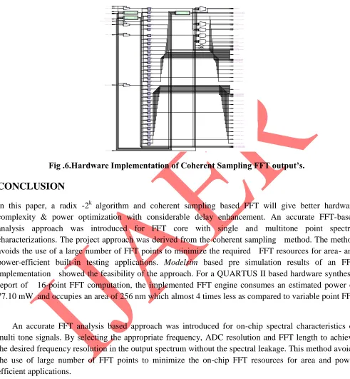
--Fig .6.Hardware Implementation of Coherent Sampling FFT output’s.
CONCLUSION
In this paper, a radix -2k algorithm and coherent sampling based FFT will give better hardware
complexity & power optimization with considerable delay enhancement. An accurate FFT-based analysis approach was introduced for FFT core with single and multitone point spectral characterizations. The project approach was derived from the coherent sampling method. The method avoids the use of a large number of FFT points to minimize the required FFT resources for area- and
power-efficient built-in testing applications. Modelsim based pre simulation results of an FFT
implementation showed the feasibility of the approach. For a QUARTUS II based hardware synthesis report of 16-point FFT computation, the implemented FFT engine consumes an estimated power of 77.10 mW and occupies an area of 256 nm which almost 4 times less as compared to variable point FFT .
An accurate FFT analysis based approach was introduced for on-chip spectral characteristics of multi tone signals. By selecting the appropriate frequency, ADC resolution and FFT length to achieve the desired frequency resolution in the output spectrum without the spectral leakage. This method avoids the use of large number of FFT points to minimize the on-chip FFT resources for area and power efficient applications.
REFERENCES
[1] Hari Chauhan, Student Member, IEEE, Yongsuk Choi, Marvin Onabajo, Member, IEEE,In-Seok
55 INTERNATIONAL JOURNAL OF ADVANCES IN ENGINEERING RESEARCH
[2] B. Murmann, “Digitally assisted analog circuits,” IEEE Micro, vol. 26, no. 2, pp. 39-47, Mar.-Apr.
2006.
[3] D. Kaczmzn, M. Shah, M. Alam, M. Rachedine, D. Cashen, L. Han, and A. Raghavan, “A
single-chip 10-band WCDMA/HSDPA 4-band GSM/EDGE SAW-less CMOS receiver with DigRF 3G
interface and +90 dBm IIP2,” IEEE J. Solid-State Circuits, vol. 44, no. 3, pp. 718-739, Mar. 2009.
[4] J. Lee and H. Lee, “A high-speed two-parallel radix -24
FFT/IFFTprocessor for MB-OFDM UWB
systems,” IEICE Trans. Fundam., vol.E91-A, no. 4, pp. 1206–1211, Apr. 2008.
[5] Y. Chen, Y. Tsao, Y. Wei, C. Lin, and C. Lee, “An indexed-scaling pipelined FFT processor for
OFDM-based WPAN applications,” IEEETrans. Circuits Syst. II, Exp. Briefs, vol. 55, no. 2, pp. 146–
150, Feb. 2008.
[6] M. Shin and H. Lee, “A high-speed four-parallel radix -24
FFT processor for UWB applications,” in