Prototype Implementation of Temperature Control
System with CAN and FreeRTOS on STM32F407
Discovery Boards
Venkat Margapuri
and Mitchell Neilsen
Department of Computer ScienceKansas State University Manhattan, KS, USA
[email protected], [email protected]
Abstract
The focus of the paper is to provide a prototype implementation of a temperature control system using the open-source real-time operating system FreeRTOS and communication via a Controller Area Network (CAN). By using low-cost components and open-source software on low-cost STM32F407 Discovery Boards with ARM Cortex M4 processors, this prototype is an ideal target for classroom use. The Discovery boards provide built-in support for 2 CAN buffers, but no transceivers. This paper presents the implementation of a Master-Slave architecture with CAN communication using LibOpenCM3 libraries with FreeRTOS and a more general CAN implementation using Hardware Abstraction Libraries (HAL). The paper further discusses the concepts of CAN messaging and its parameters in detail to be applicable for anyone wanting to set up their own network. In addition to CAN communication between STM32F407 Discovery Boards, this paper also presents a prototype implementation of a temperature control system on STM32F407 Discovery boards showing use of most standard interfaces on the boards such as GPIO and I2C. It describes the hardware components of the system and the software implementation using a combination of HAL, LibOpenCM3, and FreeRTOS.
1
Introduction
Controller Area Network (CAN) provides a broadcast type information exchange protocol. The basic principle behind CAN communication is ‘Modules Serve the Network’ (Fredriksson). The idea is that all devices on the network see any information that is transmitted by a device on the network. Devices can use filters to pick up and respond to information that they wish to receive. Every device on the network is of equal importance and there is no concept of a master and a slave, although the network
Volume 63, 2019, Pages 130–139
can be modeled to mimic a master-slave architecture. This paper starts with the theory behind CAN and basics of STM32F407 Discovery Boards to give readers background to understand the prototype.
The STM32F407 Discovery Board is a low-cost microcontroller device that is manufactured by STMicroelectronics. The board runs a 32-bit ARM Cortex M4 processor with FPU core. While the board has a plethora of features, one of the prime features of STM32F407 Discovery Board that is pertinent to this paper is its built-in support for CAN communication with 2 CAN hardware buffers.
Hardware Abstraction Libraries (HAL) and LibOpenCM3 are library sets that aid in the setup, transmission and reception of CAN messages. HAL is a product of the STMicroelectronics, whereas LibOpenCM3 is a low-level open source library for any ARM Cortex microcontrollers. CAN typically supports baud rates from 1 Kbps to 1 Mbps. Minor mismatches in the configuration of the bit timing parameters can result in error frames being generated by the STM32F407 Discovery Boards (or any other microcontroller for that matter). Hence, it is critical to compute the bit timing parameters correctly for any node that is put on the network. (Hint: An error at any one node can cause all other nodes on the network to generate errors frames). As per the CAN specification, the bit time is divided into four segments – the Synchronization Segment, the Propagation Segment, the Phase Buffer Segment 1, and the Phase Buffer Segment 2. The mathematical computation of the bit timing parameters is beyond the scope of the paper. The nominal start of each bit is indicated by the beginning a Synchronization (SYNC_SEG) Segment. The SYNC_SEG is always one-time quantum long and is used for the synchronization of the clocks. The Propagation Segment is in place to compensate for the physical delays between the nodes. The Propagation Delay is defined as twice the sum of the signal’s propagation time on the bus line, including the delays associated with the bus driver. It is programmable from 1 – 8 Time Quanta (Richards). The Phase Buffer Segments are in place to compensate for edge phase errors on the bus (Richards). Segment 1 can be lengthened, or Segment 2 can be shortened by resynchronization. Segment 1 can vary from 1 – 8 Time Quanta while Segment 2 can vary from 2 – 8 Time Quanta. In addition to these bit timing parameters, there is another parameter that needs to be understood - Synchronization Jump Width. Synchronization Jump Width (SJW) is useful to adjust the bit clock as required by a value of 1 – 4 Time Quanta to keep the bit rate of the nodes on the network in sync since a lack of synchronization in the bit rates between different nodes on the network could lead to error frames being generated.
In order to understand the bit timing parameter settings for the STM32F407 Discovery Board, it is important to understand the clock settings of the board. The STM32F407 Discovery Board has two main clocks – the System Clock and the Peripheral Clock. The micro-controller has three main clock sources that are used to drive the System Clock (SYSCLK). They are:
1. High Speed Internal (HSI) Clock: Upon every reset of the micro-controller, the HSI clock is enabled by default. The HSI clock has a maximum frequency of 16 MHz and an accuracy of 1% which is relatively low.
2. High Speed External (HSE) Clock: The STM32F407 Discovery Board has a built-in external oscillator with an 8 MHz crystal that could be used as the HSE clock. The frequency of the external clock typically varies between 4 – 16 MHz. The HSE clock can be used to achieve greater accuracy compared to the HSI clock.
3. Phase Locked Loop (PLL) Clock: The PLL can be used to enhance the clock source by a factor between 2 and 16. The input to the PLL could be HSI, HSE or HSE/ 2. The micro-controller can be driven at a maximum frequency of 168 MHz upon utilizing the HSE and PLL together to configure the clock.
set of peripherals. The clocks differ in maximum frequency as shown in Table 1. Table 1: STM32F407 Clocks and Maximum Frequencies
Clock Max. Frequency
AHB 168 MHz
APB1 42 MHz
APB2 84 MHz
The CAN peripherals used in this experiment are pins PB8 and PB9. The APB1 clock is responsible for the CAN peripherals PB8 and PB9 on the STM32F407 Discovery Board. For example, CAN communication can be established for baud rates of 125Kbps, 250 Kbps and 1000 Kbps using the parameters shown in Table 2.
Table 2: Example Baud Rates and CAN Parameter Values
Baud Rate (Kbps) Prescaler SJW Seg1 Seg2 Sampling Rate
125 21 1 13 2 87.5%
250 21 1 6 1 87.5%
1000 3 1 6 7 50%
In the rest of the paper, Section 2 specifies related work, Section 3 discusses CAN communication on STM32F407 Discovery with HAL and LibOpenCM3, Section 4 describes a Temperature Control System using STM32F407 Discovery Boards with FreeRTOS and HAL, and Section 5 concludes the paper.
2
Related Work
There are a few papers that address building a prototype of a temperature control system and Controller Area Networks (CAN). A few of the most relevant works are described below.
The development of a demand response temperature control system was performed by (Behl, 2013) in their work, ‘Demo abstract: EnergyLab-Building energy testbed for demand-response’. The key idea of the work is to design and evaluate energy efficient control and demand response strategies from buildings. The prototype which was built was that of a building with compartments for centralized heating, ventilation and air conditioning and lighting system. The prototype also included a MATLAB based front-end to run and observe the experiments.
The work, ‘Prototype implementation of real time W-CAN driver for hub to nacelle wireless communication in wind turbine. In 2017 7th International Conference on Communication Systems and Network Technologies‘ by (Munde, 2017) prototypes CAN on LPC1769 micro-controllers on FreeRTOS. The work throws light on the manner in which the utilization of CAN in control systems can enhance the overall reliability and robustness of communication within the system.
3
CAN Communication on STM32F407 Discovery Boards
3.1
Connecting Multiple Boards with CAN Transceivers
Figure 1: SN65HVD230 CAN Transceiver
In order to connect multiple STM32F407 Discovery Boards for CAN transmission, the CANH and CANL pins of the transceiver on one board are connected to the CANH and CANL pins of the transceiver on the other board, respectively. Figure 2 shows two STM32F407 Discovery boards connected via CAN transceivers.
Figure 2: STM32F407 Boards Connected for CAN Transmission
The architectural schematic shown below can be used to replicate the circuit shown in Figure 2.
Figure 3: Schematic to Connect STM32F407 Discovery Boards for CAN Transmission
3.2
CAN Data Transmission between Boards using HAL
CubeMX upon appropriate configuration is used to generate code for the CAN peripheral. This eliminates the need for the user to write any code from scratch. It can be observed in Figure 5 that the Sync Jump Width, Pre-scaler, Time Seg1 and Time Seg 2 values are set to 1, 21, 6, and 1 respectively which indicates a baud rate of 250 Kbps as outlined in Table 2.
Figure 5: CubeMX Generated Code for CAN Initialization
With CubeMX generating the boilerplate code with all the parameters in place, the user is only required to configure the microcontroller’s peripherals for transmission, enable the CAN interrupt and configure CAN parameters with the appropriate values to match a desired baud rate. An important point is that CubeMX is not a requirement for CAN on STM32F407 Discovery boards. Code in C could be written from scratch to enable the CAN peripheral using HAL on Atollic TRUEStudio IDE and a fully functioning CAN could be setup on the microcontrollers. HAL is well documented and can be accessed via documents put together by STMelectronics. The use of CubeMX only makes it easier to setup the peripherals and the clocks which is great for beginners in an academic setting.
3.3
CAN Transmission using LibOpenCM3 and FreeRTOS
LibOpenCM3 is an open-source library for Cortex M3 libraries in specific but also supports M0 and M4. Unlike HAL that has CubeMX to auto generate code; such provision is not available with the use of LibOpenCM3 libraries. Instead, a library meant for a specific functionality (CAN library, in this case) needs to be manually imported into the project and leveraged. As a result, LibOpenCM3 involves writing code from scratch to use the libraries. For this research, Visual Studio Code IDE was used along with a plugin named PlatformIO. PlatformIO is an open-source plugin that supports development of Internet of Things (IoT) software and ships with a built-in debugger that comes in handy.
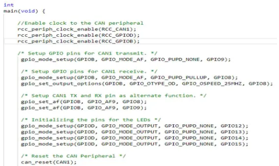
Figure 6: On-Chip Peripheral Initialization using LibOpenCM3 on STM32F407 Discovery
CAN’s design philosophy is not conducive to a Master-Slave architecture pattern since every device on the network is deemed equally important. However, the need for Master-Slave architecture calls for the implementation of a task driven application as opposed to an interrupt driven application. In order to create a task driven application, the usage of FreeRTOS is considered. Figure 7 shows three tasks created in FreeRTOS that are run on the STM32F407 Discovery Boards.
Figure 7: Tasks in FreeRTOS
The Create_Controller _Task is made to transmit a CAN message periodically as shown in Figure 8 and the Create_Blinking_Task is made to receive the CAN messages sent over and respond accordingly.
Figure 8: Controller Task Transmitting a CAN Message
Figure 9: Interactions between Controller and Worker Devices over CAN
4
Temperature Control System using STM32F407 Boards
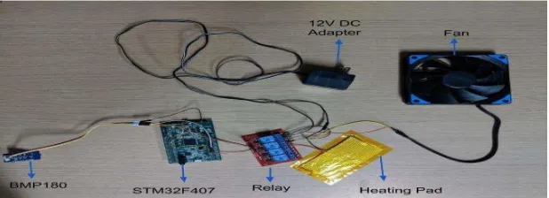
This section describes a prototype implementation of a building temperature control system which maintains temperature inside a room within a desired temperature range. The key idea of the system is that a heating system or a cooling system is turned on as and when temperature goes below or above the desired range respectively. Since this is a prototype meant for educational purposes, the system uses low cost electronic components that emulate a real time temperature control system as shown in Table 3.
Table 3. Hardware Components and Function
Hardware Component Function
BMP180 Sensor Temperature sensor
STM32F407 Discovery Supplies the power to components and executes code with FreeRTOS
Fan Acts as the cooling system
Heating Pad Acts as the heating system
Relay Acts as the switch to control heating and cooling systems 12V DC Adapter Provides sufficient voltage for the heating and cooling systems
Working Methodology
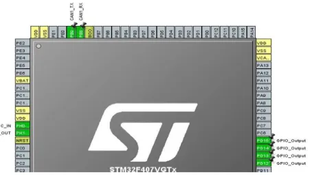
A desired temperature range i.e. a high and a low is initially set by the user. The BMP180 temperature sensor is then used to record the temperature of the environment periodically using a FreeRTOS task. As and when the temperature of the system falls outside the desired temperature range, the GPIO pin on the STM32F407 corresponding to the heating or the cooling system is toggled. Since the GPIO pin is connected to the relay, the relay switches to the corresponding temperature control system. Hence, either the heating or the cooling system is triggered. The system is then be made to remain ON till the temperature returns to the desired range and turned OFF upon doing so.
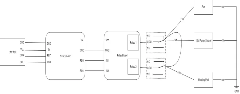
Figure 10 shows the physical connections between the hardware components of the temperature control system. The schematic shown in Figure 11 can be followed in order to emulate the circuit using suitable hardware components.
Figure 11: Schematic to Connect Temperature Control Components to STM32F407
The software implementation is done using HAL code generated by CubeMX along with the tasking mechanism in FreeRTOS. The BMP180 temperature sensor operates on the basis of I2C protocol which
is described in brief to give the reader a basic understanding.
I2C is a synchronous serial communication protocol that is well suited for the master slave
architectures in embedded systems. I2C uses two wires i.e. SDA and SCL and a ground (GND)
connection to function. The SDA i.e. the Serial Data line is used for data exchange between two devices. The data is exchanged bit by bit in bytes since I2C is synchronous. The SCL i.e. the Serial Clock line is
used to carry the clock signal and is always driven by the master. The wires are bidirectional and operate both ways to enable communication between devices. I2C messages between devices consist of the
following parameters:
1. Start and Stop Conditions: The Start condition is issued before the start of a message transmission by pulling the SDA line low before pulling the SCL line low and the Stop condition is issued at the end of a message transmission by pulling the SCL line high before pulling the SCL high.
2. Address Frame: Upon sending a Start condition, the master can send data to a slave. The first byte sent after the start condition is the address of the slave that needs to respond to the master upon the receipt of a message.
3. Read/ Write Bit: The Read/ Write bit is set to 0 when the master sends data to the slave and 1 when the slave sends data to the master.
4. ACK/ NACK Bit: Upon a successful reception of a message, the receiving device be it the master or the slave responds by sending the ACK bit. The NACK bit is sent only by the master to the slave to indicate that there is no more data left to transmit.
For the purposes of this paper, the master device is the STM32F4 Discovery board and the slave device is the BMP180 temperature sensor. Refer to (Mankar) for more information on I2C protocol.
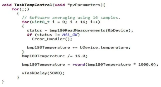
Going back to the software implementation details, in order to get a temperature value that is as close to the accurate temperature as possible, a total of 16 readings is taken and the average of the values is used to control the heating and the cooling systems. As mentioned before, CubeMX is used to generate the boilerplate code for I2C. FreeRTOS tasks are then used to periodically acquire a
The value of the variable bmp180Temperature holds the value of the temperature of the environment at a given point in time. Another FreeRTOS task is used to check if the temperature value is within the desired range. In case it is not, corresponding GPIO pin i.e. PD3 for the fan or PD1 for the heating pad is toggled as shown in Figure 13.
Figure 13: FreeRTOS Task to Check the State of the Temperature Control System
5
Conclusion
Overall, the prototype implementations of Master-Slave architecture with CAN communication and temperature control system on STM32F407 Discovery board comes in quite useful in implementing task driven applications. There are varieties of use cases in both academia and industry that could benefit from real time application systems. Due to space constraints, only critical snippets of code are presented. However, we would be happy to provide complete solutions and instructions to anyone upon request. The solutions mentioned in the paper can be leveraged in an academic setting to teach students about task driven real time applications. This would be a good step in preparing students to solve bigger problems in an industry setting.
References
Behl, M., Shah, N., Vadakedathu, L., Wheeler, D., & Mangharam, R. (2013, April). Demo
abstract: EnergyLab-Building energy testbed for demand-response. In 2013 ACM/IEEE
International Conference on Information Processing in Sensor Networks (IPSN) (pp. 303-304).
IEEE.
Fredriksson, L. B. (1995). A can kingdom. Mölndal, Sweden: Kvaser AB.
Richards, P. (2001). Understanding Microchip’s CAN Module Bit Timing. Application Note AN754, Microchip Technology Inc.
Villegas, J. M. J., Avizzano, C. A., Ruffaldi, E., & Bergamasco, M. (2015, October). A low cost open-controller for interactive robotic system. In 2015 IEEE European Modelling Symposium (EMS) (pp. 462-468). IEEE.
Munde, S. U., & Tasgaonkar, P. P. (2017, November). Prototype implementation of real time W-CAN driver for hub to nacelle wireless communication in wind turbine. In 2017 7th International Conference on Communication Systems and Network Technologies (CSNT) (pp. 97-102). IEEE.
Gay, W. Beginning STM32.
Pazul, Keith. "Controller area network (can) basics." Microchip Technology Inc 1 (1999).
Hartwich, F., & Bassemir, A. (1999, November). The configuration of the CAN bit timing. In 6th International CAN Conference (pp. 2-4).
Neilsen, M. L. (2001, June). A flexible real-time transport protocol for controller area networks. In Proceedings of the International Conference on Parallel and Distributed Processing Techniques and Applications (PDPTA’01) (pp. 250-256).