Design and Development of Slotted
Rectangular Microstrip Antennas for Hepta
Band Operation
Dr. M. Veereshappa
Associate Professor, Department of Electronics, L.V.D. College, Raichur, Karnataka, India
ABSTRACT: Design and development of slotted rectangular microstrip antenna is proposed for hepta band operation
with notch-band property. Two rectangular slots are placed on the radiating patch from its vertical edges for providing different surface current paths so as to produce six resonant modes. Both slots are kept at a distance of 0.2 cm from the non radiating edges of the patch. The antenna enhances the bandwidth of 4.81 % with a gain of 2.77 dB. Further the antenna is modified by increasing the width of the slots gives seven resonant modes and it enhances the bandwidth of 11.58 % in BW7 with peak gain of 3.56 dB. The antenna also rejects WLAN frequency interference between BW7 and
BW8. Both antennas shows broad side radiation characteristics. The proposed antenna may find application in
microwave communication systems.
KEYWORDS: Microstrip Antenna, Slot, hepta band, Broad side.
I. INTRODUCTION
Microstrip antennas (MSAs) are finding increasing applications in modern microwave communication systems because of their low profile, light weight compact size, simple in design, low cost, planar configuration, easy to fabricate and capable of operating more than one band of frequencies is quite useful because each band can be used independently for transmit receive applications. The multiband operation with notch band operation is an additional advantage, the MSAs are the better choice for these requirements. The dual, triple quad and multi band microstrip antennas are reported [3-8], design and development of notch-band antenna [9-12] etc. In this study conventional rectangular microstrip antenna designed and developed by loading rectangular slots on the radiating patch for hepta and notch-band and operation. This modification does not affect the broad side radiation characteristics.
II. DESIGN OF ANTENNA GEOMETRY
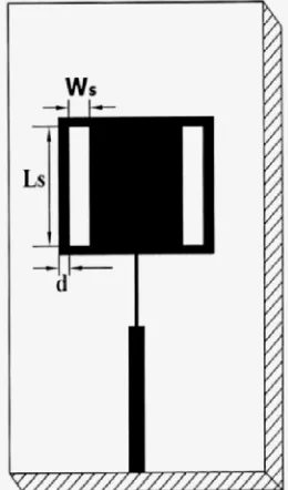
The proposed antenna is designed for 3 GHz of frequency using the equations available for the design of conventional rectangular microstrip antenna in the literature [2].The art work of the proposed antenna is sketched by using computer software Auto-CAD and it is fabricated by using photolithography process on low cost FR4-epoxy substrate material of thickness of h = 0.16 cm and permittivity r = 4.4. Figure 1 shows conventional rectangular microstrip antenna
(CRMSA). In Fig.1 the area of the substrate is L W cm. The length and width of the rectangular patch are Lp and Wp
respectively. The feed arrangement consists of quarter wave transformer of length Lt and width Wt which is connected
as a matching network between the patch and the microstripline feed of length Lf and width Wf. A semi miniature-A
Fig. 1Top view geometry of CRMSA
In Figure 2 rectangular slots are placed on the patch from its vertical edges (SRMSA) for providing different surface current paths so as to produce five resonant modes. The length and width of slots are Ls and Ws respectively and both
rectangular slots are kept at a distance of 0.2 cm from the edges of the radiating patch. The other geometry of Fig. 2 remains same as that of Fig.1.The SRMSA further modified by increasing the width of slot from 0.41 cm to 0.65 cm keeping other geometry same. The design parameters of the proposed antennas is shown in Table 1.
Table 1
Design parameters of proposed antenna Antenna
parameter
L W Lp Wp Lf Wf Lt Wt Ls Ws
Dimensions in cm
8.0 5.0 2.34 3.04 2.48 0.3 1.24 0.05 2.04 0.41
III. EXPERIMENTAL RESULTS AND DISSCUSION
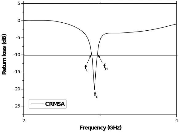
The antenna bandwidth over return loss less than -10 dB is tested experimentally on Vector Network Analyzer (Rohde & Schwarz, Germany make ZVK model 1127.8651). The variation of return loss verses frequency of CRMSA is as shown in Fig. 3. From this graph it is seen that, the antenna resonates at 2.92 GHz which is very close to the designed frequency of 3 GHz. The experimental bandwidth (BW) is calculated in percentage using the equations,
BW 2 1 c
=
f
f
×100 % (1)
f
were, f1 and f2 are the lower and upper cut of frequencies of the band respectively when its return loss reaches – 10 dB
and fc is the centre frequency of the operating band. The impedance bandwidth of CRMSA is found to be 2.40 %.
.
Fig. 3 Variation of return loss versus frequency of CRMSA
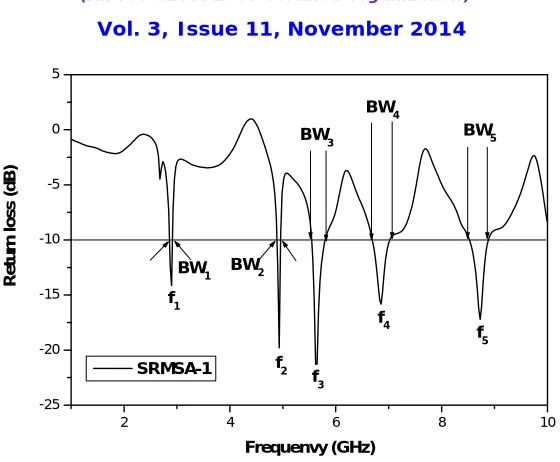
The variations of return loss versus frequency of SRMSA is as shown in Fig. 4. From this figure it is seen that, the antenna operates for five bands of frequencies BW1 and BW5. The magnitude of these operating bands measured for
BW1 and BW5 is found to be 66 MHz (2.29 %), 90 MHz (1.82 %), 250 MHz (4.41 %), 330 MHz (4.81 %) and 370
MHz (4.265 %) respectively. Hence by using two parallel slots in SRMSA the bandwidth increases by 1.77% in BW5.
These enhancements are due to the simultaneous resonance of slots along with the patch. This antenna shows useful single notch-band i.e. 4.97 to 5.54 GHz between BW2 and BW3 which is the interference of WLAN frequency range.
2 4
-25 -20 -15 -10 -5 0 5
fL fH
fC
R
e
tu
rn
l
o
s
s
(
d
B
)
Fig. 4 Variation of return loss versus frequency of SRMSA when Ws = 0.41
Figure 5 shows the variation of return loss verses frequency of SRMSA when Ws =0.65 cm. From this figure it is seen
that, the antenna operates for seven bands of frequencies BW6 t o BW12 for resonating modes f6 to f12 respectively.
These multi resonant modes are achieved due to different surface current paths by loading rectangular slots on the patch The magnitude of these operating bands measured at BW5 and BW7 is found to be 120 MHz (4.22 %), 130 MHz
(2.70 %), 710 MHz (12.55 %), 240 MHz (3.53 %), 300 MHz (4.12 %), 830 MHz (9.20 %) and 1.32 GHz (11.58 %) respectively. Hence by increasing the width of two parallel slots in SRMSA the antenna resonates for seven bands instead of five bands and also it increases the bandwidth in all the bands, the highest bandwidth found in BW8 which is
5.23 times more as compared to CRMSA and 2.61 times more than that of SRMSA of Fig. 2. The antenna also retains useful single notch-band i.e. 4.87 to 5.30 GHz between BW7 and BW8 which is the interference of WLAN frequency
range.
Fig. 5 Variation of return loss versus frequency of SRMSA when Ws = 0.65
2 4 6 8 10
-25 -20 -15 -10 -5 0 5 f 5 f4 f3 f 2 f 1 BW5 BW4 BW 3 BW2 BW1 R e tu rn l o s s ( d B ) Frequenvy (GHz) SRMSA-1
0 2 4 6 8 10 12
The gain of the proposed antennas is measured by absolute gain method. The power transmitted ‘Pt’ by pyramidal horn
antenna and power received ‘Pr’ by antenna under test (AUT) are measured independently. With the help of these
experimental data, the gain (G) dB of AUT is calculated by using the formula,
λ
P
r
0
(G) dB=10 log
- (G ) dB - 20log
t
dB
P
t
4
πR
(2)
where, Gt is the gain of the pyramidal horn antenna and R is the distance between the transmitting antenna and the
AUT. Using equation (2), the peak gain of CRMSA, SRMSA when Ws = 0.41 and SRMSA when Ws = 0.65 measured
in their operating bands is found to be 0.90 dB,2.77 dB and 3.56 dB respectively.
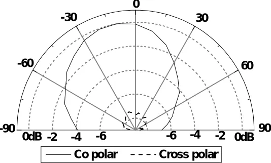
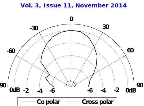
The co-polar and cross-polar radiation pattern of CRMSA, SRMSA when Ws = 0.41 and SRMSA when Ws = 0.65 is
measured at 2.92, 2.89 and 2.87 GHz and are shown in Fig 6 to 8 respectively. The obtained patterns are broad side in nature.
Fig. 6 Radiation pattern of CRMSA measured at 2.92 GHz
Fig. 7 Radiation pattern of SRMSA when Ws = 0.41measured at 2.89 GHz
-6 -6
-4 -4 -2
-2
0dB 0dB
-90 -60
-30
90 60 30
0
Co polar Cross polar
90 60 30
0
-90 -60
-30
-6
-6 -4
-4 -2
-2
0dB 0dB
Fig. 8 Radiation pattern of SRMSA when Ws = 0.65measured at 2.87 GHz
IV.CONCLUSION
From the detailed experimental study, it is concluded that, the SRMSA when Ws = 0.65is realised from conventional
rectangular microstrip antenna is quite capable in producing hepta band operation capable of enhancing the impedance bandwidth of 11.58 % which is 4.825 times more as compared to CRMSA and 2.4 % times more than that of SRMSA when Ws = 0.41 and gives peak gain of 3.56 dB. The antenna also capable of rejecting the interference of WLAN
frequency range between BW7 and BW8 (i.e. 4.87 to 5.30 GHz) and gives broad side radiation characteristics. The
antenna has simple structure and use low cost substrate material FR4.These antennas may find application in microwave communication systems.
ACKNOWLEDGEMENTS
The authors would like to thank UGC, Govt. of India. New Delhi, for sanctioning Minor Research Project. The authors also would like to thank the Chairman of Applied Electronics Dept. Gulbarga University, Gulbarga and authorities of Aeronautical Development Establishment (ADE), DRDO Bangalore for providing their laboratory facility to make antenna measurements on Vector Network Analyzer.
REFERENCES
[1] Constantine A. Balanis, Antenna theory analysis and design, John Wiley, New York, 1997. [2] I. J. Bahl and P. Bharatia, Microstrip antennas, Dedham, MA: Artech House, New Delhi, 1981.
[3] Jia- Yi Size, Kin-lu Wong, “Slotted rectangular microstip antenna for bandwidth enhancement”, IEEE Trans Antennas and Propagat vol. 48, no. 8, pp.1149-1152, 2000.
[4] S.Maci, G. Biffi Gentili P. Piazzesi and C.Salvandor,, Dual-Band Slot Loaded patch antenna,” IEEE Proc. On Microwave Antenna Propagation, no.142, pp. 0225- 232, 1995.
[5 ] K. L. Wong and K. B. Hsieh, Dual Frequency Circular microstrip antenna with a pair of Arc-shaped Slot,” Microwave Opt Technol Lett vol. 19, pp.410-412 1998..
[6] S.Hong and K.Chang, ”Single-feed triple-frequency rectangular microstrip patch antenna with pairs of spur lines, ”Electron lett.vol. 42, no.12, pp. 673-674,2006
. [7] A. Sahaya Anselin Nisha and T. Jayanthy, “Design and Analysis of Multiband Hybrid Coupled Octagonal Microstrip Antenna for Wireless Applications”, Res. J. Appl. Sci. Eng. Technol., 5(1): 275-279, 2013
[8] C. W. Jung, I. Kim, Y. Kim and Y. E. Kim. “Multiband and multifeed antenna for concurrent operation mode”. Electron lett, 43(11), pp.600-602, 2007.
[9] M. Naser-Moghadasi, L. Asadpor and B. S. Virdee, “ Compaect Ultra-Wideband slot antenna with band-notch property” Microwave and Optical Technology Letters, vol. 54, no. 8, pp.1829-1832, August 2012.
[10] Huiqing Zhai, Jinxia, Ou, Tong Li, Guihong Li Long Li and Changhong Liang, “A compact ultra-wideband antenna with two band notches” Microwave and Optical Technology Letters, vol.55, no. 3, pp.583-586, March 2013.
[11] Mohammad Ojaroudi and Nasser Ojaroudi, “Low profile slot antenna with dual band-notched function for UWB systems” Microwave and Optical Technology Letters, vol.55, no. 5, pp.951-954, May 2013.
0dB -2 -4 -6 -6 -4 -2 0dB
-90 -60
-30
90 60 30
0
BIOGRAPHY
M. Veereshappa received his M.Sc, M.Phil and Ph.D degree in Applied Electronics, from Gulbarga
University, Gulbarga in the year1987, 2008 and 2014 respectively. He is currently working as Associate Professor & H. O. D. of Electronics in L.V.D. College, Raichur since 1987. His fields of interests include Microwave Electronics. He has published twenty one papers in reputed peer reviewed International Journals and two papers in National Conference and He is the Principal Investigator for Minor Research project (MRP) sponsored by UGC New Delhi. He worked as Co-ordinator for Karnataka State Open University Mysore at L.V.D. College Study Centre Raichur for three years.