Voltage Sag Mitigation Using STATCOM with
NSVFF Control during Wind Speed Variation
in Wind Farms
Rijo Rajan 1 , Cibumol B Babu 2
Assistant Professor, Dept. of Electrical and Electronics Engineering, Providence College of Engineering,
Chengannur, Kerala, India1
Assistant Professor, Dept. of Electrical and Electronics Engineering, Lourdes Matha College of Science and Tech,
Thiruvananthapuram, Kerala, India2
ABSTRACT: Power generation from renewable energy source, the wind has grown tremendously and its growth potential is still significant. Unlike conventional sources, due to the unpredictable nature of wind and due to various aerodynamic aspects, the active power generated by wind turbines fluctuates. The power variation causes stability issues because of the fluctuation of the voltage at the point of connection of wind farm. Therefore, power quality issues especially; voltage sag is the major limiting factors for connecting wind farm into power grid, mainly the wind farm with fixed-speed induction generators. This paper investigates the use of a static synchronous compensator (STATCOM) to mitigate the sustained voltage sag of wind farm with fixed speed induction generators. A control strategy which combines negative-sequence voltage feed-forward (NSVFF) control is used to mitigate voltage fluctuation of wind farm. The simulation results show that the STATCOM significantly improves the power quality of wind farm integrated to grid.
KEYWORDS: Power quality, STATCOM, voltage sag, wind farm.
I. INTRODUCTION
The main problem regarding wind power systems is the major discrepancy between the irregular character of the primary source (wind speed is a random, strongly non-stationary process, with turbulence and extreme variations). The active power generated by wind turbines fluctuates due to the aerodynamic aspects. The power variation can cause fluctuation of the voltage at point of connection of wind farm. Therefore, power quality issues (sustained voltage sag) are the major limiting factors for connecting wind farm into power grid, especially the wind farm with fixed-speed induction generators. Voltage collapse is associated with the reactive power demands of loads not being met because of limitations on the production and transmission of reactive power. Limitations on the production of reactive power usually include generator and FACTS devices reactive power limits and the reduced reactive power produced by capacitors at low voltage levels, etc. This paper prescribes a new power injection model of STATCOM for voltage stability.
II. POWER EXTRACTED FROM WIND
The horizontal axis approach currently dominates wind turbine applications. A horizontal axis wind turbine consists of a tower and a nacelle that is mounted on the top of the tower. The nacelle contains the generator, gearbox and the rotor. Different mechanisms exist to point the nacelle towards the wind direction or to move the nacelle out of the wind in the case of high wind speeds. On small turbines, the rotor and the nacelle are oriented into the wind with a tail vane. On large turbines, the nacelle with the rotor is electrically yawed into or out of the wind, in response to a signal from a wind vane.
more blades are used for mechanical water pumping. The number of rotor blades is indirectly linked to the tip speed ratio, , which is the ratio of the blade tip speed and the wind speed:
R
(1)
Where is the frequency of rotation, R is the radius of the aerodynamic rotor and υ is the wind speed. Currently,
three-bladed wind turbines dominate the market for grid-connected, horizontal axis wind turbines. Three-bladed wind turbines have the advantage that the rotor moment of inertia is easier to understand and therefore often better to handle than the rotor moment of inertia of a two-bladed turbine. Furthermore, three-bladed wind turbines are often attributed ‘better’ visual aesthetics and a lower noise level than two-bladed wind turbines. The power of an air mass
that flows at speed υ through an area A can be calculated as follows: Power in wind.
3 1 2
w
P A (2)
Where A is intercepting area in m2, is air density in kg/m3and υ is wind speed in m/s. The power in the wind is
converted into the mechanical–rotational energy of the wind turbine rotor, which results in a reduced speed in the air mass. The power in the wind cannot be extracted completely by a wind turbine, as the air mass would be stopped completely in the intercepting rotor area. This would cause a ‘congestion’ of the cross-sectional area for the following air masses. The theoretical optimum for utilizing the power in the wind by reducing its velocity was first discovered by Betz. According to Betz, the theoretical maximum power that can be extracted from the wind is
3 1 2
w P B e t z
P A C 1 30 . 5 9 ( 3 ) 2 A
III. VOLTAGE STABILITY ISSUES OF WIND FARM
The influence of connecting a wind farm on the gird voltage is directly related to the short circuit power level. The short circuit power level in a given point in the electrical network represents the system strength. If the voltage at a remote point can be taken as constant, VS and the short circuit power level SSC in MVA is defined as V /Z where ZK is the equivalent impedance between the points concerned.
Fig.1 simple systems with an equivalent wind power generator connected to a network.
Fig.1 Illustrates an equivalent wind power generation unit, connected to a network with equivalent short circuit impedance ZK. The network voltage at the assumed infinite bus bar and the voltage at the Point of Common Coupling (PCC) are Vg and VS, respectively. The output power and reactive power of the generation unit are Pg and Qg, which corresponds to a current Ig.
*
g g
g
S I
V
(4)
g g
g
g
P j Q
I
V
(5)
The voltage difference ΔV, between the system and the connection point is given in eqn. 6.
k g k g k g k g
g g
R P X Q X P R Q
V j
V V
(6)
V Vp j Vq (7)
concepts. For a given wind power capacity P the ratio RSC = SSC / P is a measure of the strength. The voltage at PCC should be maintained within utility regulatory limits. Operation of wind turbines may affect the voltage in the connected network. If necessary, the appropriate methods should be taken to ensure that the wind turbine installation does not bring the magnitude of the voltage outside the required limits [13].
IV.VOLTAGE FLUCTUATION MITIGATION
For the power system in Fig.2, the voltage at the sending end of the power line Vs, can be approximately calculated as:
1 1
2 2
s
P R QX
V V
V
(8)
Where P and Q are the active and reactive power flow on the line, respectively; V2 is the voltage at the receiving end of the power line. Since the voltage V2 is constant but the generated active power by the wind farm is varying due to the variation of the wind speed, the voltage Vs fluctuates when the reactive power is relatively constant. However, by quickly varying the reactive power Q using fast and smooth dynamic reactive compensation from the STATCOM, the fluctuation of the voltage Vs can be mitigated [3].
Fig.2 Single line diagram of wind farm with STATCOM
V. STATCOM
The objective of the STATCOM is to provide fast and smooth voltage regulation at the point of common coupling (PCC). The STATCOM is made up of a shunt transformer, a VSC, a dc capacitor, a magnetic circuit, and a controller. If there is no energy storage device coupled to the dc link and the losses are neglected, neither shunt converter is capable of absorbing or generating real power so that only operating in the reactive domain is possible. The reactive power exchange of STATCOM with the ac system is controlled by regulating the output voltage amplitude of VSC. If the amplitude is increased above that of the ac system, the current flows through the shunt transformer from the STATCOM to the ac system, and the device generates reactive power (capacitive). If the amplitude is decreased to a level below that of the ac system, then the current flows from the ac system to STATCOM. The capacitor is used to maintain dc voltage to the VSC, which itself keeps the capacitor charged to the required levels. Thus, by controlling the VSC output voltage lead or lag with respect to the ac system voltage, the capacitor dc voltage can be decreased or increased, respectively, to control the reactive power output of the device. When the VSC voltage leads the bus voltage, the capacitor supplies active power to the system, reducing its voltage; on the other hand, when the VSC voltage lags the bus voltage, the capacitor is charged by consuming active power from the system.
VI.CONTROL STRATEGY FOR STATCOM
from abc reference frame to anti-clock wise and clock wise rotating reference frame. The matrix expression given in Eqn.9 and 10 is obtained when θ ≈ ωt +∅ .
1 1 ' 1 1 1 ' ' 1 1 '1 cos(2 )
cos
sin(2 )
s (2 )
sin 2
cos(2 )
sd P N
S S sq N S V V V V t in V (9) 1 1 ' ' ' '
cos(2 ) cos(2 )
sin(2 ) sin(2 )
sd P N
S S sq V V V V (10)
Positive-sequence and negative-sequence voltage amplitude are V and V respectively. The initial phase angle of positive-sequence and negative-sequence voltage are ∅ and ∅ respectively. Since both axes are rotating in opposite direction, the oscillating frequency 2ω corresponding to the coupling between axes. A decoupling calculation
is described in Eqn.11 and 12 to cancel the oscillations.
1 1 1 1 1 1 * ' ' * ' '
cos(2 ) sin(2 )
sin(2 ) cos(2 )
sd sd sd sq sq sq V V V V V V (11) 1 1 1 1 1 * ' * '
co s( 2 )
sin ( 2 )
sd sd sd sq sq V V V V V (12)
The structure model of the DSRF PLL can formulated form Eqn.11 and 12 and the structure is shown in Fig.3. Decoupling computation is used to ascertain the positive and negative sequence components of the unbalanced PCC voltage. Positive and negative fundamental component of the PCC voltage can be detected using The Doubly Synchronous Revolving reference Frame (DSRF) PLL method. The complete control strategy consists of PWM control and the Negative Sequence Voltage Feed-Forward control.
Fig.3 Structure model of the DSRF PLL
Fig.5 Variation of voltage at PCC without STATCOM
VII.PERFORMANCE ANALYSIS OF WIND FARM UNDER WIND SPEED VARIATION
To investigate the effect of the STATCOM with NSVFF control on power quality issues of the WTGs, a fluctuating wind varies in the range of 8-15m/s is applied to the wind farm.Fig.5 shows the response of the PCC voltage without STATCOM. The varying wind speed cause variations of the wind farm output power since output power of wind energy system is directly proportional to cube of the wind speed, this leads to fluctuations of the voltage at the PCC. Voltage fluctuates with large magnitudes and therefore causes poor power quality issues. Without any reactive power support the system voltage drops to 0.66pu. Fig.6 shows voltage and current response of wind farm at PCC with STATCOM using NSVFF control. The PCC voltage is stabilized at 0.99pu when wind farm is supported by STATCOM using Negative Sequence Voltage Feed Forward Control (NSVFF).
Fig.6 Variation of voltage at PCC with STATCOM
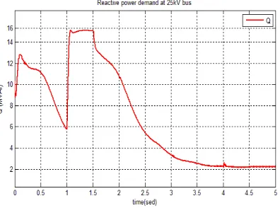
Fig.7 Variation of reactive power demand of wind farm at PCC
Fig.8 Variation of reactive power generated by STATCOM
TABLE 1PCC VOLTAGE IN PU DURING WIND FLUCTUATION
Condition without STATCOM With STATCOM
(NSVFF control)
Fluctuating wind 0.65 0.98
Table 1 shows PCC voltage in pu of wind farm without STATCOM and with STATCOM using NSVFF control. Power quality like sustained voltage sag is a main issue related with wind farm during turbulence. Results show that STATCOM with NSVFF control improves voltage stability of wind farm at PCC.
VIII. CONCLUSION
results shows that sustained voltage sag of grid integrated wind farm at PCC during symmetrical and unsymmetrical fault conditions is subdued and there by improved the PCC voltage stability.
REFERENCES
[1] Larsson, Ake (2002) "Flicker emission of wind turbines during continuous operation."IEEE transactions on Energy Conversion Vol.17 No.1, March 2002, pp. 114-118.
[2] Gaztanaga, Haizea, Ion Etxeberria, Dan Ocnasu, and Seddik Bacha (2007) "Real-time analysis of the transient response improvement of fixed-speed wind farms by using a reduced-scale STATCOM prototype." Power Systems, IEEE Transactions on Vol.22 No.2, May 2007, pp. 658-666.
[3] Qiao, Wei, and Ronals G. Harley. "Power quality and dynamic performance improvement of wind farms using a STATCOM." Power Electronics Specialists Conference, 2007. PESC 2007. IEEE. IEEE, 2007.
[4] Jazayeri, M., and M. Fendereski (2007). "Stabilization of gird connected wind generator during power network disturbances by STATCOM." Universities Power Engineering Conference, 2007. UPEC 2007. 42nd International. IEEE, 2007.
[5] Muyeen, S. M and M. Fendereski (2007). "Stabilization of wind farms connected with multi machine power system by using STATCOM." Power Tech, 2007 IEEE Lausanne. IEEE, 2007.pp. 1182-1186
[6] Rodriguez, Pedro, Josep Pou, Joan Bergas, J. Ignacio Candela, Rolando P. Burgos, Dushan Boroyevich (2007) "Decoupled double synchronous reference frame PLL for power converters control." Power Electronics, IEEE Transactions on Vol.22 No.2, March 2007: 584-592.
[7] Fadaeinedjad, Roohollah, Gerry Moschopoulos, and Mehrdad Moallem (2008). "Using STATCOM to mitigate voltage fluctuations due to aerodynamic aspects of wind turbines." Power Electronics Specialists Conference, 2008. PESC 2008. IEEE. IEEE, 2008.
[8] Qi, L., J. Langston, and M. Steurer (2008). "Applying a STATCOM for stability improvement to an existing wind farm with fixed-speed induction generators."Power and Energy Society General Meeting-Conversion and Delivery of Electrical Energy in the 21st Century, 2008 IEEE. IEEE, 2008.
[9] Chen, Ning Minhui Qian, Lingzhi Zhu, Liangzhong Yao, Fubao Wu,Mei Chen and Ningbo Wang (2012). "A coordinated reactive power and voltage control system for wind farm grid integration." Power System Technology (POWERCON), 2012 IEEE International Conference on. IEEE, 2012.
[10] Naimi, Djemai, Tarek Bouktir, and Ahmed Salhi (2013). "Improvement of transient stability of Algerian power system network with wind farm." Renewable and Sustainable Energy Conference (IRSEC), 2013 International. IEEE, 2013.
[11] Abdelsalam, A. A., & Sharaf, A. M. (2012). A novel facts compensation scheme for power quality improvement in wind Smart Grid. In Electrical & Computer Engineering (CCECE), 2012 25th IEEE Canadian Conference, April 2012. pp. 1-4.
[12] Sharaf, A. M., Aljankawey, A., & Altas, I. H. (2007). A Novel Voltage Stabilization Control Scheme for Stand-alone Wind Energy Conversion Systems. In Clean Electrical Power, 2007. ICCEP'07. International Conference. May 2007. pp. 514-519.
[13] Chen, Z. (2005). Issues of connecting wind farms into power systems. In Transmission and Distribution Conference and Exhibition: Asia and Pacific, 2005 IEEE/PES. pp. 1-6
[14] Zhang, Xinyan , Xuan Cao, Weiqing Wang and Chao Yun (2013). Fault Ride-Through Study of Wind Turbines " Journal of Power and Energy Engineering 1, April 2013: pp.25-29.