Design and Development of High Voltage
Multi Output DC Power Supply with
Modulated Signal
Dilip Y1, Krishnamurthy V2, Manjunatha V3, Siddik E4 and Venkatesan T5
UG Scholar, Department of ECE, Adhiyamaan College of Engineering, Hosur, TN, India1,2,3,4 Associate Professor, Department of ECE, Adhiyamaan College of Engineering, Hosur, TN, India5
Abstract:The main objective of this is to design and assemble the high voltage multiple output Digital power supply with modulation for microwave oscillators. The design is been done and printed on the boards using the printed circuit board (PCB) technology. Various electronics components are used. After printing the circuit on the board various through whole components are been mounted and soldered.
KEYWORDS: Multi voltage o/p transformer, octal base, power transistors.
I.INTRODUCTION
In previous discussion of linear acceleration, we have - the microwave power which is used in the accelerator as a sort of magical substance which is provided upon demand in any quantity and with any time structure required. This is obviously an oversimplification. Indeed, the generation and transportation of RF power is a major industry in its own right, with customers far beyond the pedestrian world of accelerators. In this set of notes, we will briefly describe the role of klystrons, modulators, and pulse compression in the production of RF power.
II. KLYSTRONS
The klystron is the ubiquitous source of RF power in accelerators today; if any lab in the world uses anything but
Klystrons to produce megawatt levels of RF power, the authors are not aware of it. The klystron is at heart a narrow-band vacuum-tube amplifier which operates at microwave frequencies. The basic idea of the klystron is shown schematically in figure.
• A continuous electron beam is emitted by the klystron’s cathode and accelerated to high voltage (usually non-relativistic) in a DC gun.
• The electron beam passes through a resonant cavity (the input cavity) which is excited by an external source of RF power (typically in the kilowatt range) at the resonant frequency of the cavity
• The beam passes through a drift tube, in which the accelerated electrons travel faster and the decelerated ones travel slower, resulting in a beam which is bunched at the frequency of the RF drive signal; thus a significant fraction of the beam’s power has been moved from DC to the drive frequency.
• The beam now passes through a series of output cavities which are resonant at the same frequency as the input cavity; these cavities act like accelerating structures – they become beam-loaded, resulting in a decelerating voltage at the resonant frequency (identical to the beam’s bunching frequency) – thus the power is transferred from the beam to the cavities.
interesting steps in greater detail.
BEAM PRODUCTION
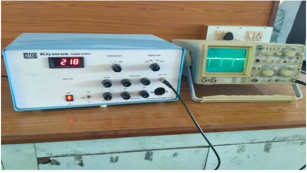
The beam is produced by heating a cathode to release electrons; these electrons are then accelerated by a DC voltage (here Vklys). Because the voltage is typically 500 kV or less, the beam is only barely relativistic and is thus subject to longitudinal and transverse forces due to the mutual repulsion of electrons, so-called space charge forces.A klystron is a specialized linear-beam vacuum tube, invented in 1937 by American electrical engineers Russell and Sigurd Varian, which is used as an amplifier for high radio frequencies, from UHF up into the microwave range.Amongtheglobalthresholding techniques,Scientific Microwave manufactures two type of power supplies for the microwave benches in X-Band. Klystron Power Supply For the klystron based microwave bench. Klystron power supply generates required beam and repeller voltage for the X-Band klystron tube like 2K25. It is very stable and contains the short circuit protection circuit. Also it has amplitude and frequency modulation circuits for the generation of 1 KHz square wave and the saw tooth wave. Specifications Model SKPS-610 Beam Supply:
Voltage Range: 200-450 V continuously Variable
Current: 50mA Max
Regulation: Better than 0.5% for 10% variation in the mains supply voltage
Ripple: Less than 5 mV rms
Repler supply Voltage Range: 10V to 270 V DC Continuously variable with respect to klystron cathode
Regulation: 0.25% for 10% variation in the mains supply voltage
Heater Supply: 6.3 V DC (Regulated)
MODULATION
Square Wave: Max. Amplitude: + 110 V peak to peak Freq.: 500 Hz-2000Hz Amplitude and frequency continuously variable
Sawtooth: Amplitude: -60 V max. peak to peak Freq.: 50 Hz-150 Hz Amplitude and frequency continuously variable
Operating Voltage: 230V 10%, 50 Hz, A.C.
III. E XISTING SYSTEM TRIODE
A triode is an electronic amplifying vacuum tube (or valve in British English) consisting of three electrodes inside an evacuated glass envelope: a heated filament or cathode, a grid, and a plate (anode). Developed from Lee De Forest's 1906 Audion, a partial vacuum tube that added a grid electrode to the thermionic diode (Fleming valve), the triode was the first practical electronic amplifier and the ancestor of other types of vacuum tubes such as the tetrode and pentode. Its invention founded the electronicsage, making possible amplified radio technology and long-distance telephony. Triodes were widely used in electronics devices such as radios and televisions until the 1970s, when transistors replaced them. Today, their main remaining use is in high-power RF amplifiers in radio transmitters and industrial RF heating devices. In recent years there has been a resurgence in demand for low power triodes due to renewed interest in tube-type audio systems by audiophiles who prefer the sound of tube-based electronics.
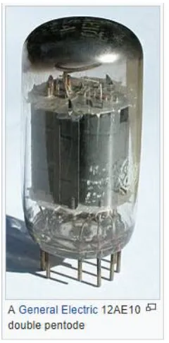
PENTODE
Fig3:A general electric pentodemodel
IV.PROPOSED SYSTEM
Klystrons can produce far higher microwave power outputs than solid state microwave devices such as Gunn diodes. In modern systems, they are used from UHF (hundreds of megahertz) up to hundreds of gigahertz (as in the Extended Interaction Klystrons in the Cloud Sat satellite). Klystrons can be found at work in radar, satellite and wideband high-power communication (very common in television broadcasting and EHF satellite terminals), medicine (radiation oncology), and high-energy physics (particle accelerators and experimental reactors). At SLAC, for example, klystrons are routinely employed which have outputs in the range of 50 MW (pulse) and 50 kW (time-averaged) at 2856 MHz The Arecibo Planetary Radar uses two klystrons that provide a total power output of 1 MW (continuous) at 2380 MHz Popular Science's "Best of What's New 2007"[10][11] described a company, Global Resource Corporation, currently defunct, using a klystron to convert the hydrocarbons in everyday materials, automotive waste, coal, oil shale, and oil sands into natural gas and diesel fuel.
V.RESULT
In order to evaluate the performance of the surface the defects detection system, experiment sare carried out using the real-time An electronic oscillator can be made from a klystron tube, by providing a feedback path from output to input by connecting the "catcher" and "buncher" cavities with a coaxial cable or waveguide. When the device is turned on, electronic noise in the cavity is amplified by the tube and fed back from the output catcher to the buncher cavity to be amplified again. Because of the high Q of the cavities, the signal quickly becomes a sine wave at the resonant frequency of the cavities.
Fig 5: Output waveform 1
Fig 6: Output waveform 2
VI.CONCLUSION
Toreplacetheexisting power suppy mode at high voltage of multi output dc power supply with modulated signal by regulated power supply, that may indicate the low power supply to high power supply. The klystron is at heart a narrow-band vacuum-tube amplifier which operates at microwave frequencies. The basic idea of the klystron is shown.
REFERENCES
1. Pond, Norman H. "The Tube Guys". Russ Cochran, 2008
2. Gilmour, A. S. (2011). Klystrons, Traveling Wave Tubes, Magnetrons, Cross-Field Amplifiers, and Gyrotrons. Artech House. pp. 3– 4. ISBN1608071847.
3. Varian, R. H.; Varian, S. F. (1939). "A High Frequency Oscillator and Amplifier". Journal of Applied Physics. 10 (5): 321. Bibcode:1939JAP....10..321V. doi:10.1063/1.1707311.
4. Varian, Dorothy. "The Inventor and the Pilot". Pacific Books, 1983 p. 189 5. Varian, Dorothy. "The Inventor and the Pilot". Pacific Books, 1983 p. 187
6. George Caryotakis (November 18, 1997). "Invited paper: The Klystron: A microwave source of surprising range and endurance" (PDF). American Physics Society: Division of Plasma Physics Conference, Pittsburg, PA. Stanford, CA: Stanford SLAC. 7. http://www.radiomuseum.org/tubes/tube_v-260.html
8. Bonifacio, R.; Corsini, R.; Pierini, P. (15 March 1992). "Theory of the high gain optical klystron" (PDF). Physical Review A. 45 (6): 4091. Bibcode:1992PhRvA..45.4091B. doi:10.1103/physreva.45.4091. Retrieved June 24, 2014.
9. Campbell, D. B.; Hudson, R. S.; Margot, J. L. (2002). "Advances in Planetary Radar Astronomy". Review of Radio Science. 1999-2002: 869–899.