ISSN(Online): 2320-9801
ISSN (Print): 2320-9798
I
nternational
J
ournal of
I
nnovative
R
esearch in
C
omputer
and
C
ommunication
E
ngineering
(An ISO 3297: 2007 Certified Organization)
Vol. 3, Issue 7, July 2015
Video Shot Detection in Embedded System
Using Different Color Model
Shivaleela Hullyal1, Dr. Jharna Majumdar2, Kiran S3
M.Tech, Dept of CSE, Nitte Meenakshi Institute of Technology, Bangalore, India1
Dean R & D, Prof & Head, Dept of CSE (PG), Nitte Meenakshi Institute of Technology, Bangalore, India2
Asst. Professor, Dept of CSE (PG), Nitte Meenakshi Institute of Technology, Bangalore, India3
ABSTRACT: Video is a series of continuous sequence of images captured from a single camera.Video shot detection
is a process of detecting the number of shots in an entire video and also detection of the frames that constitute the shots. The shot detection in the video is the initial and the important stage in the organization of large video data and also plays an important role in the process of video summarization.
The different approaches to the video shot detection are the Pixel difference method, Histogram difference (Bin-to-Bin) method, Mutual information method and the weighted variance and histogram variation method. These different techniques are used with the threshold parameter for the purpose of video shot detection. The different color models are also used for the evaluation of performance measures. And then the performance of the results obtained by each of these methods with different colors is evaluated. As a result, the best color model that works efficiently with the video shot detection method is presented as well performed.
KEYWORDS:Video shot detection, color models, mutual information, histogram, weighted variance, beagle board
I. INTRODUCTION
The series of image captured at a constant interval is known as a video. Video can be classified as the scenes, shots and frames. A scene has a common specific semantic significance and it is a collection of contiguous shots. The continuous sequence of frames captured from a single camera without pause is known as a shot. The set of one or more shots which focuses on a single object is known as a scene. The transition between two different shots is known as a Video shot boundary. The first step in simplification of processing of any video is the shot transition detection.
Video shot detection is the major step in any type of video processing. Some of the types of VSD techniques are Pixel difference method, Histogram (Bin to Bin, Chi-square, intersection) method, Mutual information method, Edge change ratio method, scaled metrics, Weighted variance and histogram variation method and so on.
Color refers to the combination for different wavelengths of light. It is dependent on the subjective interpretation of human brain. The visual system of the human being or the human eye can distinguish a large number of different color intensities and different color shades. The human eye depends on the light source that contains the wavelength and also the objects that absorb the wavelength that are reflected by the light. Thus the extra information is contained in an image and these can be used to simplify the video or the image analysis.
The standard method to describe a specific color is given by the color models. These is done by creating the 3D co-ordinate system. There are many types of color models. Some of them are RGB, CMY, HSI, HSV, CMYK, YIQ, YUV, YCbCr and so on.
II. PLATFORM
ISSN(Online): 2320-9801
ISSN (Print): 2320-9798
I
nternational
J
ournal of
I
nnovative
R
esearch in
C
omputer
and
C
ommunication
E
ngineering
(An ISO 3297: 2007 Certified Organization)
Vol. 3, Issue 7, July 2015
purpose computers and some of them are the consumption of power is low compared to general purpose computer, the cost per-unit is less and the size of embedded system is very little compared to the general purpose computers. The embedded system operating ranges are strong and it is designed to be operated in any type of conditions and environment. The embedded systems can be used in limited processing resource.
A. Software Platform: Ubuntu is the secured, fastest and safe operating system. The main goal of ubuntu is to be secure. Since ubuntu is an hardware independent software, it is been used for the implementation of VSD algorithms
B. Hardware Platform: The BeagleBoard is a hardware that consumes less power. The cost of beagle board is low and is fan-less. It is a open source board that is available easily. The CPU core of beagle board is faster and has more RAM. The open source development was the main aim of the beagle board and the amount of power used in beagle board is 2W. Since the power consumption is less, it does not require additional cooling and head sinks. Hence the beagle board is fan-less system. The beagle board has all the functionality of the basic general computer.
Fig.1. BeagleBoard
III.PROPOSED METHOD
In the video shot detection process different types of methods are used to detect the shots in a particular video. Some of those methods used are as follows,
A. Pixel Difference Method:
The pixel difference method is the basic and the simple method in order to detect the video shot. In these particular method, the shot is detected by comparing the pixel intensity value of the two consecutive frames. The formula used for calculation of the pixel difference is given as,
D(i,i+1) = ∑ | , − , |
Where, i is the number of the frame, j is the feature value of each frame. D(I, i+1) is the difference computed
between two frames and fi,j is the particular frame.
After the calculation difference between all the pair of frames in a video, threshold value is computed. Then if the pixel differences[1] is greater than the computed threshold, then it is assumed that the shot at that particular frame is detected
B. Histogram (Bin-to-Bin) Difference Method:
The most reliable algorithm of the Histogram based shot boundary detection is the bin-to-bin method[2]. In these method, the histogram is calculated for the each frame separately. Then the histogram of two consecutive frames are compared. Then the different between the histograms of these individual frames is calculated and are stored. These calculation is made using the formula
CHD = 1
M∗N |F (r, g, b)−F (r, g, b)|
( ) ( ) ( )
Where, CHD is the histogram difference[5], i is the particular frame number, M is the row and N represents the column. F is the frame and r, g, b the red, green and blue color spaces respectively of the video.
ISSN(Online): 2320-9801
ISSN (Print): 2320-9798
I
nternational
J
ournal of
I
nnovative
R
esearch in
C
omputer
and
C
ommunication
E
ngineering
(An ISO 3297: 2007 Certified Organization)
Vol. 3, Issue 7, July 2015
C. Mutual Information Method:
The amount or quantity of information transported from one frame to other frame is known as mutual information. The shot is detected if there is a minimum transition between the frames.
, , , and , is the three N * N matrices that carries the transition information for each frame. The mutual
information is calculated from frame 1 to frame 2 and from frame 2 to next frame and so on. These mutual information[6] is calculated for each color component separately using the formula below,
, = -∑ ∑ , (i,j) log ,
( , )
, ( ) , ( )
Where , is the mutual information. f is the particular frame.
Then the total mutual information is calculated by adding the individual mutual information. These is computed using the formula
, = , + , + ,
The calculation of the joint entropy is done using the following formula:
, = = -∑ ∑ , (i,j) log , ( , )
Then the total joint entropy is calculated by adding the individual mutual information. These is computed using the formula.
, = , + , + ,
Finally the minimum value of the mutual information at a particular frame shows the shot detected. Fig 6.5 constitutes the output reference graph for the mutual information method of video shot detection.
D. Weighted Variance and Histogram Variation Method:
In this particular method, the weighted mean and variance[4] is computed for detecting the shot in an video. it also generates the adaptive threshold using these calculated Weighted mean and variance. The working procedure of these method is that each frame in the video is compared with its consecutive frame and the difference is calculated. Then the weighted mean values is calculated iteratively of each pixels difference values of two consecutive frames. The weighted variance is also calculated by using these mean values. The weighted mean and the weighted variance is calculated using the below formula[4],
m’ = ∑ ∑ ( ( , ) ( ( , )
×
v’ = ∑ ∑ ( , )
′
×
Where, ‘m' indicates the weighting mean of difference and v’ is weighting variance of the difference frame. Fi is a current frame, fi-1the subsequent frame of fi, and di is difference frame. H and W are the vertical and horizontal size of the frame. Wd is the weighting factor.The weighing factor should be larger in order to get the clear shot boundry.
The different approches of video shot detection methods are implemented using different color models. These is done in order to evaluate the performance measure i,.e to find which color model works well for particular VSD method. Some of the different types of color models used here are as follows:
YCbCr color model:
YCbCr is the simplest color model in the color image processing. Y component is the luminance color. Cb and Cr are the chromo components. Y component that is the luminance is the black or Cb is obtained from taking the blue difference from green color. Thr Cr color component is obtained from taking the red difference from green color.
The formula used for the calculation of YCbCr is:
Y = ( R * 0.299 + G * 0.587 + B * 0.114) CB = (128 - ( R * 0.168736 - G * 0.331264 + B * 0.5)) CR = (128 + ( R * 0.5 - G * 0.418688 + B * 0.081312))
YIQ color model:
The main application of YIQ color model is the color television. The recording of the RGB color model constitutes the YIQ model. The abbreviation of YIQ model is yellow, inphase, and quadrature. Yellow is nothing but it constitutes the luminance. All the information or the data required for the black and white television is captured or collected by the luminance. And it also captures the brightness of the particular color. inphase, and quadrature are the two chromatic components of hardware oriented models.
ISSN(Online): 2320-9801
ISSN (Print): 2320-9798
I
nternational
J
ournal of
I
nnovative
R
esearch in
C
omputer
and
C
ommunication
E
ngineering
(An ISO 3297: 2007 Certified Organization)
Vol. 3, Issue 7, July 2015
Y = ( R * 0.2899 + G * 0.587 + B * 0.114 ) I = ( R * 0.596 - G * 0.275 - B * 0.3218 ) Q = ( R * 0.212 - G * 0.528 + B * 0.311 )
YUV color model:
The formula used for the calculation of YUV is:
Y = (R * 0.299 + G * 0.587 + B * 0.114) U = 0.565 * ( B – Y )
V = 0.713 * ( R - Y )
HSI Color model:
The color can be represented by the three types of quantities such as hue, saturation and intensity. These hue, intensity and saturation is known as the HSI color model. Red color is the base for the measurement of hue. And the distance from axis of triangle is the saturation. These all colors on solid surface are fully saturated. Those are the pure colors. The spectrum on the axis of solid is known as grayscale spectrum. Hue is not defined for these type of colors
The formula used for the calculation of HSI is: M = max (R, G, B)
m = min (R, G, B)
H = Cos-1 . . (if G≥ )
H = 360 - Cos-1 . . (if B > G)
I = ( )
S = (if I> 0) S = 0 (if I =0)
The HSV Model:
The hue, saturation and value are the three quantities in which the colors are represented. These hue, value and
saturation is known as the HSV color model. The value represents thebrightness of the image or the video. Red color is
the base for the measurement of hue. The main advantage of hue is that the color circles is easily identified. Color circles in the sense is the relationship between tones or the image. The tones, shades can be easily generated.
The formula used for the calculation of HSV is: M = max (R, G, B)
m = min (R, G, B) V =
S = (if M > 0)
S = 0 (if M = 0)
H = Cos-1 . . (if G≥ )
H = 360 - Cos-1 . . (if B > G)
CMY Color model:
The CMY color model is described as subtractive model. The RGB color model is defined as what amount is to be added to black color in order to get a specific color. But in case of CMY color model, it depends on what amount of color should be subtracted from white color in order to get a specific color. In these case of CMY, the primary colors are cyan, magenta and yellow. Whereas the Red, green and blue are known as the secondary colors.
The formula used for the calculation of CMY is:
C = M = Y =
ISSN(Online): 2320-9801
ISSN (Print): 2320-9798
I
nternational
J
ournal of
I
nnovative
R
esearch in
C
omputer
and
C
ommunication
E
ngineering
(An ISO 3297: 2007 Certified Organization)
Vol. 3, Issue 7, July 2015
K = 1-max(R1,G1,B1)
Where R1,G1 and B1 are,
R1 = G1 = B1 =
IV.RESULTS A. Results of different video shot detection techniques
Fig 2 Output of pixel difference method Fig 3.Output of histogram difference method Fig 4. Output of weighted variance method
Fig 5 Output of mutual information method Fig 6 Output graph of mutual information method
The figure 2 to 5 shows the input and the gray frame for different videos. And the figure 6 is the graph obtained for mutual information method. The total shots detected for each methods using different videos is shown in table I
TABLE I. NUMBER OF SHOTS DETECTED FOR THE DIFFERENT VIDEO SHOT DETECTION METHODS
Methods Video 1 Video 2 Video 3 Video 4
Pixel difference 13 27 9 21
Histogram difference 32 24 7 24
Mutual information 25 14 8 13
Weighted variance 27 32 9 23
B. Results for VSD methods using different color models 1) Pixel Difference Method
ISSN(Online): 2320-9801
ISSN (Print): 2320-9798
I
nternational
J
ournal of
I
nnovative
R
esearch in
C
omputer
and
C
ommunication
E
ngineering
(An ISO 3297: 2007 Certified Organization)
Vol. 3, Issue 7, July 2015
Fig 9 Output of Pixel difference method using YUV color model Fig 10 Output of Pixel difference method using CMY color model
Fig 11 Output of Pixel difference method using HSI color model Fig 12 Output of Pixel difference method using HSV color model
2) Histogram (Bin-to-Bin) difference method
Fig 13 Output of Histogram difference method using YCbCr color Fig 14 Output of Histogram difference method using YIQ color model
ISSN(Online): 2320-9801
ISSN (Print): 2320-9798
I
nternational
J
ournal of
I
nnovative
R
esearch in
C
omputer
and
C
ommunication
E
ngineering
(An ISO 3297: 2007 Certified Organization)
Vol. 3, Issue 7, July 2015
Fig 17 Output of Histogram difference method using HSI color model Fig 18 Output of Histogram difference method using YCbCr color model
The above figures from figure 7 to 18 shows the output of different VSD methods using different color models. The number of shots detected for the different VSD methods using different color models is as in table II of analysis part
TABLE II. NUMBER OF SHOTS DETECTED FOR PIXEL DIFFERENCE AND HISTOGRAM DIFFERENCE METHOD USING DIFFERENT COLOR SPACES
Pixel Difference
Video 1 Video 2 Video 3 Video 4 Histogram
difference
Method Video 1 Video 2 Video 3 Video 4
YCBCR 11 23 7 24 YCBCR 13 29 10 5
CMYK 4 31 9 25 CMY 9 24 6 45
YUV 4 26 2 33 YUV 4 39 6 19
YIQ 11 36 7 23 YIQ 8 34 14 58
HSI 15 25 6 25 HSI 11 33 11 33
HSV 14 25 5 25 HSV 13 13 11 22
V. ANALYSIS
The tables in these section describes about the analysis done based on the results obtained by different VSD approaches. Video 1 refers to the sports video shown in figure 1. Video 2 refers to the football video shown in figure 5. Video 3 refers to the Anewhorizon video shown in figure 3. And video 4 refers to the Cricket video shown in figure 2.
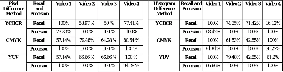
A. Recall and precision analysis:
Recall and precision are the two commonly used metrics for performance assessment. Recall quantifies what proportions of correct shots are detected. And Precision quantifies what proportions of the detected shots are correct.
The formula for the calculation of recall and precision is:
Recall =
Precision =
In these above recall and precision formula, missed shots are the shots which are actually present in the video and not identified by the algorithm. False positive is the shots in which its detected by the algorithm but are not actually present in the video.
TABLE III. RECALL/PRECISION ANALYSIS FOR PIXEL AND HISTOGRAM (BIN-TO-BIN)DIFFERENCE METHOD USING DIFFERENT COLOR SPACES
Pixel Difference
Method
Recall and Precision
Video 1 Video 2 Video 3 Video 4 Histogram Difference Method
Recall and Precision
Video 1 Video 2 Video 3 Video 4
YCBCR Recall 100% 58.97 % 50 % 77.41% YCBCR Recall 100% 74.35% 71.42% 16.12%
Precision 73.33% 100 % 100 % 100% Precision 68.42% 100% 100% 100%
CMYK Recall 57.14% 79.48% 64.28 % 80.64 % CMYK Recall 100% 61.53% 42.85% 100%
Precision 100% 100 % 100 % 100 % Precision 81.81% 100% 100% 76.27%
YUV Recall 57.14% 66.66 % 66.66 % 100 % YUV Recall 100% 79.48% 42.85% 61.2%
ISSN(Online): 2320-9801
ISSN (Print): 2320-9798
I
nternational
J
ournal of
I
nnovative
R
esearch in
C
omputer
and
C
ommunication
E
ngineering
(An ISO 3297: 2007 Certified Organization)
Vol. 3, Issue 7, July 2015
YIQ Recall 100% 92.30 % 92.20 % 74.18 % YIQ Recall 100% 87.17% 100% 100%
Precision 73.33% 100 % 100 % 100 % Precision 88.88% 100% 100% 68.23%
HSI Recall 100% 64.10 % 42.85 % 80.64 % HSI Recall 100% 78.57% 78.57% 94.2%
Precision 65.21% 100 % 100 % 100 % Precision 73.33% 100% 100% 100%
HSV Recall 100% 64.10 % 42.85 % 80.64 % HSV Recall 100% 78.57% 78.57% 70.9%
Precision 66.66% 100 % 100 % 100 % Precision 68.42% 100% 100% 100%
Figure 19 Graphs for Pixel difference method using different color spaces
Figure 20 Graphs for Histogram difference (Bin-to-Bin) method using different color spaces
B. Result obtained by the analysis:
ISSN(Online): 2320-9801
ISSN (Print): 2320-9798
I
nternational
J
ournal of
I
nnovative
R
esearch in
C
omputer
and
C
ommunication
E
ngineering
(An ISO 3297: 2007 Certified Organization)
Vol. 3, Issue 7, July 2015
TABLE IV. PIXEL DIFFERENCE METHOD AND HISTOGRAM DIFFERENCE METHOD ANALYSIS RESULTS.
Pixel Different Method Histogram (Bin-to-Bin) Different Method
Rank 1 2 3 4 5 6 Rank 1 2 3 4 5 6
Models YIQ CMY YCbCr HSV HSI YUV Models YIQ HSI CMY HSV YUV YCbCr
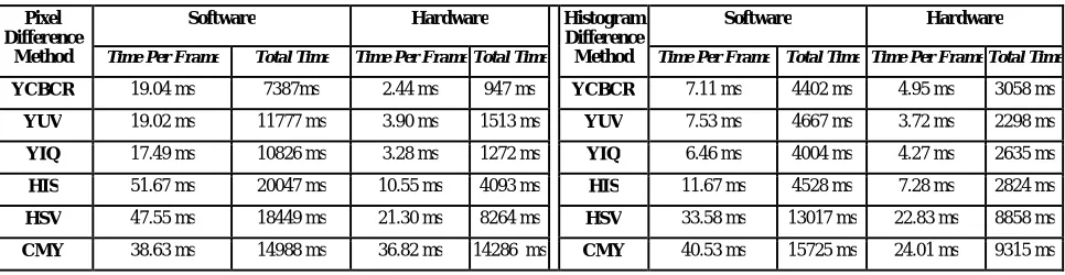
C. Timing Analysis for the VSD method using different color models:
TABLE V. TIMING ANALYSIS FOR PIXEL DIFFERENCE AND HISTOGRAM (BIN-TO-BIN)DIFFERENCE METHOD USING DIFFERENT COLOR SPACES
Pixel Difference
Method
Software Hardware Histogram
Difference Method
Software Hardware
Time Per Frame Total Time Time Per Frame Total Time Time Per Frame Total Time Time Per Frame Total Time
YCBCR 19.04 ms 7387ms 2.44 ms 947 ms YCBCR 7.11 ms 4402 ms 4.95 ms 3058 ms
YUV 19.02 ms 11777 ms 3.90 ms 1513 ms YUV 7.53 ms 4667 ms 3.72 ms 2298 ms
YIQ 17.49 ms 10826 ms 3.28 ms 1272 ms YIQ 6.46 ms 4004 ms 4.27 ms 2635 ms
HIS 51.67 ms 20047 ms 10.55 ms 4093 ms HIS 11.67 ms 4528 ms 7.28 ms 2824 ms
HSV 47.55 ms 18449 ms 21.30 ms 8264 ms HSV 33.58 ms 13017 ms 22.83 ms 8858 ms
CMY 38.63 ms 14988 ms 36.82 ms 14286 ms CMY 40.53 ms 15725 ms 24.01 ms 9315 ms
VI.CONCLUSION AND FUTURE WORK
The Pixel difference method is the simplest and the commonly used method for the purpose of video shot detection. The histogram difference technique is less complex method. Using color models gives out maximum performances and enhances the results than using the grey level for the different VSD approches.
As per the implementation, it can be concluded that the YIQ color model works with high performance for different video shot detection methods than the other color models.
REFERENCES
1. Malay Kumar Kundu, Jaydeb Mondal, ’A Novel Technique for Automatic Abrupt Shot Transition Detection’, IEEE, 2012.
2. Upesh Patel, Pratik Shah, Pradip Panchal, ’ Shot Detection using Pixel wise Difference with Adaptive Threshold and Color Histogram Method in Compressed and Uncompressed Video’, International Journal of Computer Applications (0975 – 8887) Volume 64– No.4, February 2013
3. Swati D. Bendale, Bijal.J.Talati, ‘Analysis of Popular Video Shot Boundary Detection Techniques in Uncompressed Domain’, International Journal of Computer Applications (0975 – 8887) Volume 60– No.3, December 2012
4. Guillaume Lemaitre, Mojdeh Rastgoo, Warakorn Gulyanon, ‘Real Time Image Processing: Shot detection’,
5. Saurabh Thakare ,’ Intelligent Processing and Analysis of Image for Shot Boundary Detection’, International Journal of Emerging Technology and Advanced Engineering. February 2012
6. Lenka Krulikovska, Jaroslav Polec,’An Efficient method for shot cut detection’ , World Academy of Science, Engineering and Technology 63.2012
BIOGRAPHY
Shivaleela Hullyal, presently pursuing Master’s of Technology from Nitte Meenakshi Institute of Technology, Bangalore, Karnataka, India. Also have completed Bachelor’s of Engineering from Channabasaveshwara Institute of Technology, Gubbi, Tumkur, Karnataka, India. Her area of interest is Digital Image Processing, Video Shot Detection, Embedded system..
Dr. Jharna Majumdar, presently the Dean of R&D and the HOD of CSE (PG). She served DRDO from 1990 to 2007 and retired as Scientist G and Head of Aerial Image Exploitation Division, Aeronautical Development Establishment (DRDO), Bangalore, India.Dr. Majumdar received B.Tech (Hons.) in Electronics and Electrical Engineering and Post Graduate in Computer Technology from Indian Institute of Technology Kharagpur in 1969 and 1970 respectively. She received her PhD (Electrical Engineering) in 1980.