Power Analysis Attack on Hardware Implementation of
MAC-Keccak on FPGAs
Pei Luo1, Yunsi Fei1, Xin Fang1, A. Adam Ding2, and Miriam Leeser1 and David R. Kaeli1
1
Department of Electrical and Computer Engineering, Northeastern University, Boston, MA 02115
[email protected], [email protected], [email protected], [email protected], [email protected]
2 Department of Mathematics, Northeastern University, Boston, MA 02115
Abstract. Keccak is the hash function selected by NIST as the new SHA-3 standard. Keccak is built on Sponge construction and it provides a new MAC function called MAC-Keccak. These new algorithms have raised questions with regards to side-channel leakage and analysis attacks of Keccak. So far there exists prior work on attacks of software implementations of MAC-Keccak, but there has been no comprehensive side-channel vulnerability assessment of its hardware implementation. In this paper we describe an attack on the θ step of the first round of MAC-Keccak implemented on an FPGA. We construct several different side-channel leakage models and implement attacks based on them. Our work shows that an unmasked hardware implementation of SHA-3 is vulnerable to power-based side-channel attacks.
1
introduction
Keccak was selected as the winner of the NIST hash function competition in 2012 to become the SHA-3 standard [1]. Keccak uses the Sponge construction [2] in which message blocks are XORed into the state bits and then invertibly permuted [3]. Sponge construction is completely different from the previous hash standards and thus opens up new questions and challenges in side-channel analysis (SCA).
A message authentication code (MAC) is a short piece of information generated by hash functions to provide integrity and authenticity assurances on the message. MAC is important in crypto systems because it facilitates integrity checking and proof of origin. Sponge construction allows Keccak to securely create a MAC by hashing the concatenation of the key and the message (P =K||M) in a cryptographic mode, called MAC-Keccak [2,3,4]. This MAC construction is different from previous MAC methods and has attracted much attention.
Keccak has been implemented in software or a library for various general-purpose processors, embed-ded processors, and DSPs. In addition, there have also been hardware implementations of Keccak, which can accelerate hash computations in security-sensitive applications. As an example, a virtual network server typically uses a hash function both to verify the identity of its clients and the integrity of the messages sent by the clients. Hardware implementations of hash functions are preferred for their high throughput. High-speed integrated circuits (ICs) and FPGAs-based hash modules are widely used in cryp-tographic systems, Trusted Platform Modules (TPM), and crypto processors. However, the side-channel security resiliency of hardware implementations of MAC-Keccak has not been evaluated quantitatively.
In [5], six SHA-3 candidates (including Keccak) were analyzed for side-channel leakage for the first time. In the paper, the authors analyzed the feasibility of attacking MAC-Keccak at the θ step in the first round and proposed the basic steps for the attack. They presented a general side-channel attack feasibility analysis for all six candidates, though no detailed leakage models or attack methods are given for Keccak.
In additions to the bare algorithm of MAC of Keccak, the designers of Keccak also suggested methods to protect Keccak implementations from power analysis attacks [8,9]. Random masking is an effective countermeasure. They showed that two shares are required in software implementations and three shares are required in hardware implementations.
Compared to the software implementations of MAC-Keccak [6,7], we anticipate much lower side-channel leakage of hardware implementations of MAC-Keccak with their highly parallel implementations (versus the temporally spread-out software implementations). Thus, side-channel attacks on a hardware implementation of MAC-Keccak would be much more challenging to implement. Up until now, there has not been much prior work along this direction - side-channel analysis of hardware MAC-Keccak remains an open problem. Without a good understanding of the sources and amount of side-channel leakage of MAC-Keccak, any protection against side-channel attacks cannot be evaluated accurately either. To address these issues and facilitate secure MAC-Keccak design and implementation, in this paper we propose several side-channel leakage models of hardware MAC-Keccak and launch practical power analysis attacks on the implementation. To the best of our knowledge, this is the first work which develops concrete side-channel leakage models, power analysis attack methods and attack results on a hardware MAC-Keccak implementation. In light of the popular usage of Keccak as the new hash standard, our work should make a significant contribution for side-channel security analysis of SHA-3. We further discuss the factors that affect side-channel leakage of MAC-Keccak and suggest countermeasures to improve its system security.
The rest of the paper is organized as follows. In Section 2, we introduce the MAC-Keccak algorithm, the several power leakage models we adopt for attacking it, and correlation analysis results that verify the proposed leakage models. In Section 3, we implement correlation power analysis (CPA) based on the models we introduce in Section 2 to break MAC-Keccak. In Section 4, we discuss the effect of Keccak key-length on SCA and suggest countermeasures against power analysis attacks. In Section 5, we conclude the paper.
2
Keccak and the side-channel leakage models
2.1 Keccak Hash Function and MAC-Keccak
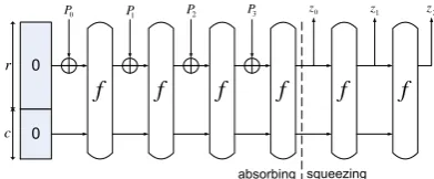
Keccak is a hash function family based on the Sponge construction, as shown in Fig. 1 [3,2,4]. Keccak has two phases: 1) absorbing and 2) squeezing. In the absorbing phase, the message is broken into blocks (each block size is r bits, where r is the bit rate), which are absorbed iteratively by the permutation functionf. Eachf function works on a state at a fixed lengthb=r+c, where the bit raterdetermines the implementation speed, while the capacity cdetermines the security length. In the squeezing phase, outputs are squeezed also byf functions and the length of the output is configurable (a multiple of r bits).
f
f
f
f
f
f
r
c 0
P P1 P2 P3 z0 z1 z2
Fig. 1.The Sponge construction
When using hash functions in MAC, there exists the commonly used HMAC construction which accepts a messageM and a keyK, and generates the corresponding digest [7] :
For Keccak, another MAC construction, MAC-Keccak [2,3,4] is recommended by the Keccak designers as:
M AC(M, K) =H(K||M). (2)
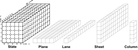
The default Keccak mode is Keccak-1600, with r= 1024 andc= 576. All of the 1600-bit states are organized in a 3-D array, as shown in Fig. 2. Each bit is addressed with three coordinates, written as S(x, y, z), x, y∈ {0,1, ...,4}, z∈ {0,1, ...,63}. 2-D entities, plane andsheet, and 1-D entities,lane and
column, are also defined in Keccak and shown in Fig. 2. A plane PY contains all state bits S(x, y, z)
for which y =Y; similarly, a sliceSLZ ={S(x, y, z), z =Z}; a sheet SHX ={S(x, y, z), x=X}. A lane LX,Y contains all state bits S(x, y, z) for which x = X and y = Y; similarly, a columnCX,Z = {S(x, y, z), x=X, z=Z}; a rowRowY,Z ={S(x, y, z), y=Y, z=Z}.
0 1 2 3
4 5 6
…
63
4 3
2
1
0
y
z
0 1 2 3 4 x
Fig. 2.Terminology used in Keccak
The f permutation functions of Keccak-1600 consist of 24 rounds of operations, where each round has five sequential steps:
Ri+1=ι◦χ◦π◦ρ◦θ(Ri), i∈ {0,1,· · · ,23} (3)
in whichR0is the initial input.
Details of each step are described below:
−θis a linear operation which involves 11 input bits and outputs a single bit. Each output state bit is the XOR between itself and two intermediate bits produced by its two neighbor columns. The operation is given as follows:
S0(x, y, z) =S(x, y, z)⊕(⊕4
i=0S(x−1, i, z)) ⊕(⊕4
i=0S(x+ 1, i, z−1)). (4)
The two intermediate bits are the parity of the two columns,⊕4
i=0S(x−1, i, z) and⊕4i=0S(x+1, i, z−1), respectively.
−ρandπare permutations over the bits of the state.
−χ is a non-linear step that contains mixed binary operations. Every bit of the output state is the result of an XOR between itself and the AND result of one neighboring bit and the NOT of another neighboring bit along the x-axis:
S0(x, y, z) =S(x, y, z)⊕(S(x+ 1, y, z)·S(x+ 2, y, z)). (5)
−ιis a binary XOR with a round constant.
2.2 The θ Operation
For the standard VHDL implementation Version 3.1 provided online by keccak.noekeon.org [10], each round takes one clock cycle and the five steps (θ, ρ, π, χ and ι) are all implemented in combinational circuits. In this paper, we attack theθstep of the first round.
As described in [6],θoperation is computed over two successive steps. In the first step,θ1 calculates the parity of each column and compresses a 1600-bit state into a 320-bit plane called theθplane:
θplane(x, z) =⊕4y=0S(x, y, z)
x∈ {0,1, ...,4}, z∈ {0,1, ...,63}. (6)
θ1 can be viewed as 320 independent operations, each of which XORs the five bits in a column to generate one bit of parity.
In the second step, θ2computes the XOR between every bit of the state and two neighboring parity bits of theθplane, and outputsθout.
θout(x, y, z) =S(x, y, z)⊕θplane(x−1, z) ⊕θplane(x+ 1, z−1)
x, y∈ {0,1, ...,4}, z∈ {0,1, ...,63}. (7)
2.3 Side-channel Leakage Models
In the hardware implementation of MAC-Keccak, all the five steps in each round are executed in one clock cycle, and the intermediate variables used for attacks on the software implementations may not be correlated with the power traces. Thus we cannot use the leakage models for software implementations [6,7] directly for hardware systems. For the standard hardware implementation of MAC-Keccak [10], we will describe the four side-channel leakage models in this section.
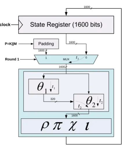
The structure of the standard Keccak hardware implementation [10] is shown in Fig. 3, where one state register holds both the input and output of a round operation. In the round operations, the first round loads the messageP in using a multiplexer, and other rounds take the state register output as input to the following five-step operation. Note here that after performing padding, M includes both the message bits and appended padding bits. For the simplified setting in this paper, we set the length of K||M as 1024 bits, thus there is only one message block. We still useP to denote the input to the first round for convenience.θcan be split further intoθ1andθ2, and the other four steps are considered together in a combinational module. We denote the latency of theθ1 operation ast1 and the latency of theθ2operation as t2.
For the standard hardware implementation, we describe the operations and discuss important time points in the first cycle:
– The state register reg is cleared before each MAC-Keccak operation, thus O(θ1) and O(θ2) are initialized at 0. At time 0, the message and key after padding (P) is loaded into the output of MUX (we ignore the delay of the MUX here).
– Att2,O(θ2) changes from 0 toP, because its input fromO(M U X) already changed toP while the other input (θ1’s output) remained 0.
– Att1,O(θ1) changes from 0 toθplane.
– Att1+t2,O(θ2) changes fromP toθout as a response to the inputO(θ1)’s changing from 0 toθplane.
In general, for hardware implementations (either FPGA or ASIC), the power model of an intermediate variable is the Hamming Distance (HD) model, i.e., the power consumption of this intermediate state and the operation driving the state is linearly dependent on the HD between the value before the operation and the value after the operation. We then have the following 2 side-channel leakage models:
2
t21600 MUX
1600
0 1
P=K||M
Round 1 t3
1
t11600
320 1600
1600 2 t
Fig. 3.Structure of Keccak hardware implementation
2. Model II: At t1+t2, the intermediate variable O(θ2) changes from P to θout, and the HD is HD(P, θout). Similarly, there should exist a time point on the power trace that has a good correlation between its power value andHD(P, θout).
To verify the above side-channel leakage models, we implemented the official VHDL description of Keccak [10,11] on an Sasebo-GII [12] board which contains a Xilinx Virtex-5 FPGA. We use the Xilinx ISE 14.6 for implementation with all of the default settings for synthesis, mapping and routing. From the post-mapping results, we find that there are 320 look-up-tables (LUTs) for theθ1 module, and just 320 LUTs for the top plane in theθ2 module instead of 1,600 LUTs for all theθout bits. This is because the synthesis tool optimized the implementation and combines other parts ofθwith following operations (ρ, π, χandι). Thus we anticipate that the leakage for Model II will be weaker than expected.
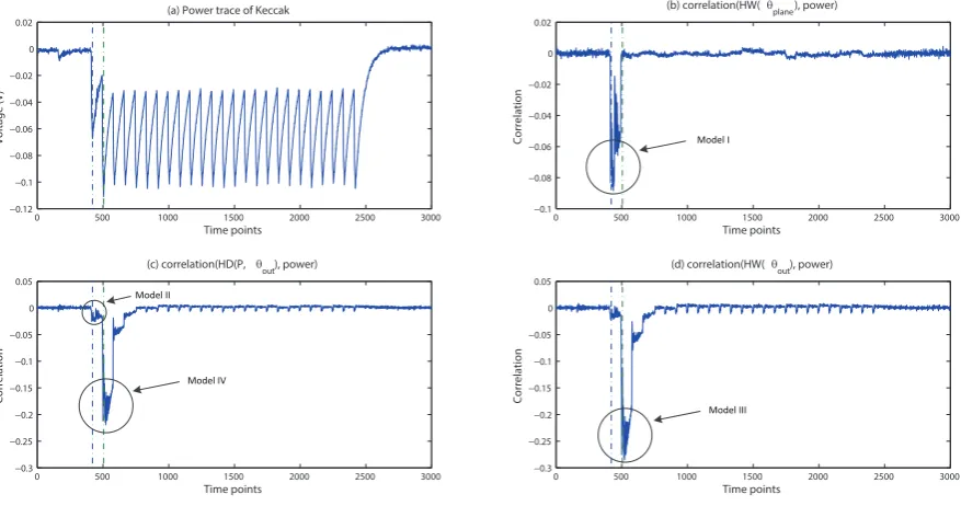
Then we collect power traces from our MAC-Keccak implementation running at 12 MHz using an Agilent MSOX4104A oscilloscop. We use 700,000 traces to find correlations based on Models I and II. We show one power trace and Pearson correlation [13,14] results in Fig. 4. Fig. 4(a) shows one example power trace of MAC-Keccak, where the first trough corresponds to the loading of message M into the padding module and thenP to theθmodule. From Fig. 4(b)(c), we can see that the side-channel power leakage for Model I and Model II are both noticeable (with the highest correlation reaching -0.09 and -0.03 respectively) in the first cycle (shown by two dashed lines). Meanwhile, we notice an even stronger correlation between the HD(P, θout) and the power at the beginning of the second round (with the highest correlation reaching -0.2, as shown in Fig. 4(c)). This point may be the moment the contents of the state register change from 0 toR1.
We anticipate some leakage signals in the second round as well. Similar to the first cycle, we identifies the operations and associated time points in the second cycle.
– At the beginning of the clock cycle, the state register stores the first round result, and the contents of the state register change from 0 to R1.
0 500 1000 1500 2000 2500 3000 −0.12 −0.1 −0.08 −0.06 −0.04 −0.02 0 0.02 Time points Voltage (V)
(a) Power trace of Keccak
0 500 1000 1500 2000 2500 3000
−0.1 −0.08 −0.06 −0.04 −0.02 0 0.02 Time points Correlation
(b) correlation(HW(θ
plane), power)
0 500 1000 1500 2000 2500 3000
−0.3 −0.25 −0.2 −0.15 −0.1 −0.05 0 0.05 Time points Correlati on
(c) correlation(HD(P, θ
out), power)
0 500 1000 1500 2000 2500 3000
−0.3 −0.25 −0.2 −0.15 −0.1 −0.05 0 0.05 Time points Correlati on
(d) correlation(HW(θ
out), power)
Model I
Model III Model IV
Model II
Fig. 4.Power trace and the correlations
However, R1 is the result of the 5-step operation which includes the θ step and others (ρ, π, χ, ι). The key-dependence ofR1should be random, according to the hash function design principle. We try to seek leakage signals related toθout (rather than R1) that contain the key information during the second round.
Surprisingly, Fig. 4(c)(d) show that there are actually time points on the power traces strongly corre-lated withHW(θout) andHD(P, θout). We hypothesize that due to the inherent algorithmic correlation betweenθout,R1 andP, we have two more power leakage models for the second cycle:
1. Model III:The state register output changes from 0 toR1. There exists a time point in the second clock cycle that is correlated withHW(θout) (actually HW(R1)).
2. Model IV:The output of multiplexer changes fromP toR1. There exists a time point in the second clock cycle that is correlated withHD(P, θout) (actuallyHW(R1)).
To verify the previous hypothesis about correlations, we randomly generated 200,000 messages and ran Keccak on them. The correlation results are as follows:
correlation(HD(P, R1), HD(P, θout)) = 0.175 correlation(HW(R1), HD(P, θout)) = 0.344 correlation(HW(R1), HW(θout)) = 0.542
. (8)
We find that the correlation between HW(R1) and HW(θout) is higher, which also explains why Model III has a stronger leakage (with correlation reaching −0.29) than Model IV (with correlation reaching−0.22). Models II, III and IV all involveθout and extract the same key information. Therefore, we choose to use Model III, which has the highest correlation (attack effectiveness) for our attacks.
3
Side-channel attacks on MAC-Keccak
In this section, we show how to launch CPA on MAC-Keccak to recover the key bits. Keccak allows the use of a variable-length key. We start with a key length of 320 bits (i.e., the key fills the bottom plane in the input state, and the message length is 1024−320 = 704 bits). The Sponge function (shown in Fig. 1) contains only onef function. We will discuss the effect of key length on attacks in Section 4.
3.1 CPA based on Model III
Next, we show how to extract the relationship between every two lanes of the key plane, based on power Model III.
For Model III, P =K||M where the unknown part is the keyK (320 bits), and the known part is the messageM (704 bits). According to (7), the Hamming weight for a single bit in model III is:
HW(θout(x, y, z)) =HW(S(x, y, z)⊕θplane(x−1, z) ⊕θplane(x+ 1, z−1)) =HW(S(x, y, z)⊕
(⊕4
y=0S(x−1, y, z))⊕(⊕ 4
y=0S(x+ 1, y, z−1))). (9)
Equation (9) shows that the operation is on two neighboring columns of the bit, which include 8 bits of the known M and 2 bits of the unknown K. This side-channel power leakage will give information related to the XOR of these 2 unknown key bits,S(x−1,0, z)⊕S(x+ 1,0, z−1), to the attacker.
To increase the leakage signal strength of CPA, instead of using 1 bit in a column for the select function, we use 4 bits (y = 1,2,3,4) instead. To make a balance between the leakage signal and the attack complexity, each time we can attack multiple bits (l,0< l≤64) in each key lane. The larger the l, the stronger the leakage signal, but also the higher complexity due to enumeration of the key bits. The multi-bit Hamming weight model (III) becomes:
Σzi+=li−1Σy4=1HW(θout(x, y, z))
i∈ {0,1, ...,63}, l∈ {1,2, ...,64} (10)
and we can recoverS(x−1,0, Z)⊕S(x+ 1,0, Z−1), x∈ {0,1,· · ·,4}, Z= [i:i+l−1].
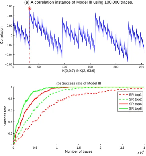
We choose l = 8 along the key lane, and run CPA based on Model III to recover the relationship between the two key bytes. One CPA attack instance and the empirical success rate results are shown in Fig. 5.
Fig. 5(a) shows the correlation analysis result for key guesses based on Model III using 100,000 traces. It shows that the correct key candidate has the highest correlation, reaching 0.055. The correlation trace for MAC-Keccak is very different from those for previous crypto algorithms such as AES or DES. This is because CPA performed on block ciphers such as AES attacks SBox, which is a non-linear operation and a small difference on the key guesses results in a big difference in the select function value. For MAC-Keccak,θis a linear operation and one bit key change has a limited affect on the Hamming weight of the output value. Fig. 5(b) gives the CPA success rates (SRs) based on Model III, which include four modes: the correct key is ranked top one according to the correlation result, ranked in the top 2, top 4 and top 8, respectively. Fig. 5(b) shows that the success rate increases when we use a less accurate ranking. The success rates all approach to 100%, and require 10,000 traces for ranking in top 8, 20,000 traces for ranking in top 2, and about 30,000 traces for top 1.
0 50 100 150 200 250 −0.06
−0.04 −0.02 0 0.02 0.04 0.06
K(0,0:7) ⊕ K(2, 63:6)
Correlation
(a) A correlation instance of Model III using 100,000 traces.
0 0.5 1 1.5 2 2.5 3
x 104 0
0.2 0.4 0.6 0.8 1
Number of traces
Success rate
(b) Success rate of Model III
SR top1 SR top2 SR top4 SR top8
32
Fig. 5.Success rate curves based on model III
3.2 Recover key bits of one lane based on Model I
In leakage Model I, the correlation is between power andHW(θplane), andθ1does not involve operations between two key lanes. According to (6), each bit of theθplaneis decided by 4 bits ofM and 1 bit ofK in one column. Thus, we can use this model to recover the key bits in one key lane directly.
For a single key bit, the SNR may be very low for (6), and more than one key bit should be attacked concurrently to increase the signal-to-noise ratio (SNR). To strike a balance between SNR and complexity, we attack 8 bits for each key lane at once. For the first 8 bits in lanex, the Hamming weight is:
HW(θplane(x,0 : 7)) =Σz7=0(⊕4
y=0S(x, y, z)). (11)
The CPA model is:
correlation(Σz7=0(⊕4
y=0S(x, y, z)), power). (12)
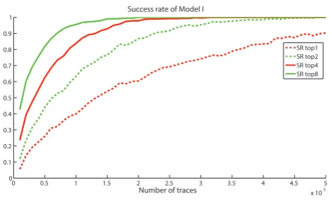
The key byte guess with the highest correlation is the right key byte. The success rates of CPA, based on the above attack model, are shown in Fig. 6.
From Fig. 6 we can see that when using about 500,000 traces, we can recover one byte of one key lane with SR around 90% while there are 8 bytes in each lane. The success rates are much lower for Model I than for Model III due to the weaker correlation. Using this method, we can recover all 64 bits in one lane. Combined with the SCA method in Section 3.1, we can recover the other key lanes to get the whole key plane.
0 0.5 1 1.5 2 2.5 3 3.5 4 4.5 5 x 10⁵ 0
0.1 0.2 0.3 0.4 0.5 0.6 0.7 0.8 0.9 1
Number of traces
Succe
ss rate
Success rate of Model I
SR top1 SR top2 SR top4 SR top8
Fig. 6.Success rate based on model I
4
Further discussion about the key-length and countermeasures
In this section, we extend the results found in the previous experiments and analyze SCA with different key lengths. Then we discuss countermeasures against this kind of power analysis attacks.
4.1 Different Parameters for MAC-Keccak
Note that the official hardware implementation [10] has different parameters (rate and capacity) from FIPS 202 [1], which was only published recently in April 2014. These parameter differences will not affect the SCA of MAC-Keccak because the power leakage models and attack methods remain the same.
4.2 Key Length
In our FPGA implementation of MAC-Keccak, we assumed that the key length is 320 bits, which is just the size of one plane such that there will be no operation between key bits in the same column. Previous work [6] discussed the effect of key length on SCA. Here, we will summarize the effect of key length on SCA under our leakage and attack models.
– key-length ≤plane-size×0.8: In this situation, the key bits take no more than 4 lanes in the key plane. For Keccak-1600, it means key-length <256, and there is interaction between key lanes and known message lanes in the bottom plane. One leakage model (Model III or IV) is enough to recover all the key bits.
– plane-size×0.8< key-length≤plane-size: In this situation, only one lane is mixed with key bits and message bits in the first plane. The leakage models (I and III) have to be combined to recover the key bits. We used 320 bits as the key length to describe our attacks in previous sections.
– key-length > plane-size: In this situation, the key bits occupy more than the first plane. Models I, II, III, and IV will involve more than two key bits for a single bit θ operation. Thus the attack complexity increases rapidly as described in [7]. We will investigate concrete attacks in this scenario in future work.
4.3 Extend the Attack Methods
and intermediate variables that carry meaningful key information would be a challenge. In addition, the leakage models and correlations would all be different from theθstep, as shown in Fig. 5.
In this work, we apply the usual CPA by choosing the key candidates with the highest correlations as the correct key, shown in Fig. 5. The linearity ofθleads to a structure in the correlation patterns in Fig. 5(a). We can use this pattern to improve the CPA attack by selecting multiple crest points in the correlation trace and use the peak points to speculate the correct key. This is because all the crest points should have very small difference from the true key (e.g., 1 bit difference). These crest points can give information about the right key to avoid key enumeration when the number of traces are limited. We will investigate this in future work.
4.4 Countermeasures
General protection schemes for hardware cryptographic systems include power-balanced circuit [15,16], masking [9], and randomization [17,18]. In this section, we discuss countermeasures for Keccak, specifi-cally based on the previously described leakage and attack models. General protection methods, such as power balanced circuits, are omitted here.
As described in Section 4.2, MAC-Keccak with key-length ≤plane-sizeis insecure and the attack difficulty increases rapidly with the key length. Thus the first and easiest countermeasure against SCA is to increase the key-length above a plane size.
The second countermeasure is using masking to increase the attack complexity, as described in [8,9,19]. This makes the power consumption not only depend on the key bits and plaintext, but also the random numbers generated inside the FPGA and IC devices. Results in [9] and [13] show that the number of traces required for SCA in a masked system is much larger than for a unprotected implementation. Thus masking should be implemented on both the linear and nonlinear parts to hide the secret information from attackers.
Another concern for the hardware implementation is the initial state of the state register. The leakage models proposed in Section 2 are based on the official hardware implementation [10] which has the state register initialized to 0. The state register changes from 0 to R1 still leaks key information as shown in Section 2. To avoid such leakage, the state register can be initialized to a random number which is unknown to the attackers, and thus the attack difficulty will be much higher. All the random number generations will incur hardware and execution time overhead though.
5
conclusion
In this paper, we explore multiple side-channel leakage models of MAC-Keccak and implement CPA based on these models. Results show that MAC-Keccak has strong side-channel leakages and these leakages can be used by attackers to extract the secret key. We discuss factors which affect side-channel leakage and countermeasures against SCA. For future work, we will investigate additional and more efficient attacks on general MAC-Keccak implementations (with different key lengths, bit rates and capacities). We will also design secure MAC-Keccak with effective countermeasures, and assess their security thoroughly.
All power traces used in this paper are publicly available athttp://tescase.coe.neu.edu.
Acknowledgment
This work is supported in part by NSF under grants SaTC-1314655 and MRI-1337854.
References
1. N. F. Pub, “DRAFT FIPS PUB 202: SHA-3 standard: Permutation-based hash and extendable-output functions,”Federal Information Processing Standards Publication, 2014.
3. G. Bertoni, J. Daemen, M. Peeters, and G. Van Assche, “Keccak sponge function family main document,”
Submission to NIST (Round 2), 2009.
4. G. Bertoni, J. Daemen, M. Peeters, and G. Assche, “The Keccak reference,”Submission to NIST (Round 3), January, 2011.
5. M. Zohner, M. Kasper, M. Stottinger, and S. A. Huss, “Side channel analysis of the SHA-3 finalists,” in
Design, Automation & Test in Europe Conference & Exhibition (DATE), 2012, pp. 1012–1017.
6. M. M. Taha and P. Schaumont, “Differential power analysis of MAC-Keccak at any key-length.” in Interna-tional Workshop on Security, 2013, pp. 68–82.
7. M. Taha and P. Schaumont, “Side-channel analysis of MAC-Keccak,” inIEEE Int. Symposium on Hardware-Oriented Security and Trust (HOST), 2013, pp. 125–130.
8. G. Bertoni, J. Daemen, M. Peeters, and G. Van Assche, “Building power analysis resistant implementations of Keccak,” inSecond SHA-3 candidate conference. Citeseer, 2010.
9. G. Bertoni, J. Daemen, N. Debande, T.-H. Le, M. Peeters, and G. Van Assche, “Power analysis of hardware implementations protected with secret sharing,” inIEEE/ACM International Symposium on Microarchitec-ture Workshops (MICROW), 2012, pp. 9–16.
10. Keccak Hardware implementation in VHDL Version 3.1, 2014 (accessed May 14, 2014). [Online]. Available: http://keccak.noekeon.org/KeccakVHDL-3.1.zip
11. “SHA-3 FPGA implementation,” http://satoh.cs.uec.ac.jp/SAKURA/research/SHA-3.html. 12. “Evaluation environment for side-channel attacks,” http://www.risec.aist.go.jp/project/sasebo/.
13. A. Ding, L. Zhang, Y. Fei, and P. Luo, “A statistical model for higher order DPA on masked devices,” in
Cryptographic Hardware and Embedded Systems CHES 2014, 2014, vol. 8731, pp. 147–169.
14. Y. Fei, Q. Luo, and A. A. Ding, “A statistical model for DPA with novel algorithmic confusion analysis,” in
Cryptographic Hardware and Embedded Systems–CHES 2012, pp. 233–250.
15. K. Tiri and I. Verbauwhede, “A logic level design methodology for a secure DPA resistant ASIC or FPGA implementation,” inProceedings of the conference on Design, automation & test in Europe, 2004, p. 10246. 16. S. Guilley, P. Hoogvorst, Y. Mathieu, R. Pacalet, and J. Provost, “CMOS structures suitable for secured
hardware,” inProceedings of the conference on Design, Automation and Test in Europe, 2004, p. 21414. 17. M.-L. Akkar and C. Giraud, “An implementation of DES and AES, secure against some attacks,” in
Cryp-tographic Hardware and Embedded Systems (CHES), 2001, pp. 309–318.
18. P. Luo, A. Y.-L. Lin, Z. Wang, and M. Karpovsky, “Hardware implementation of secure Shamirs secret sharing scheme,” inIEEE International Symposium on High-Assurance Systems Engineering, 2014, pp. 193–200. 19. B. Bilgin, J. Daemen, V. Nikov, S. Nikova, V. Rijmen, and G. Van Assche, “Efficient and first-order DPA