Study on the dynamic properties of AM-SLM AlSi10Mg alloy
using the Split Hopkinson Pressure Bar (SHPB) technique
Bar Nurel1*, Moshe Nahmany2,3, Adin Stern3, Nahum Frage3 and Oren Sadot1
1Mechanical Engineering Department, Ben Gurion University of the Negev, P.O.B. 653, Beer Sheva, 8410501, Israel 2Materials Department, Nuclear Research Center – Negev, P.O.B. 9001, Beer Sheva, 8410900, Israel
3Materials Engineering Department, Ben Gurion University of the Negev, P.O.B. 653, Beer Sheva, 8410501, Israel
Abstract. Additive manufacturing by Selective Laser Melting of metals is attracting substantial attention, due to its advantages, such as short-time production of customized structures. This technique is useful for building complex components using a metallic pre-alloyed powder. One of the most used materials in AM-SLM is AlSi10Mg powder. Additively manufactured AlSi10Mg may be used as a structural material and it static mechanical properties were widely investigated. Properties in the strain rates of 5×10²–1.6×10³ s-1 and at higher strain rates of 5×10³ –105 s-1 have been also reported. The aim of this study is investigation of dynamic properties in the 7×10²–8×10³ s-1 strain rate range, using the split Hopkinson pressure bar technique. It was found that the dynamic properties at strain-rates of 1×10³–3×10³ s-1 depend on a build direction and affected by heat treatment. At higher and lower strain-rates the effect of build direction is limited. The anisotropic nature of the material was determined by the ellipticity of samples after the SHPB test. No strain rate sensitivity was observed.
1 Introduction
Additive Manufacturing (AM) was first seen approximately 30 years ago in Austin TX, what is debatably the first AM machine. This machine used a laser to selectively melt layers of polymer and, later, metals [1] to construct 3D prototypes. The free-forming design, material flexibility, and nearly-full density products enables the Selective Laser Melting (SLM) technology to be implemented in a variety of industries, such as medical, aerospace and automotive. The SLM is a complex process that requires strict conditions to achieve the desired properties. Any AM-SLM machine can have a different AM algorithm, feedstock quality, built chamber atmosphere and scan strategy (the path that the laser beam follows) which will affect the final product properties. A description of an AM laser melting system can be seen in figure 1. Many improvements to the SLM technology have been achieved by intense research. One of the important issues relates to the fast cooling of the melt during the laser scan. Apelian [2] shows that adding silicon, which has a high heat of fusion, prolongs the alloy’s fluid phase by releasing heat into the melt during solidification. This heat contribution slows the solidification rate and the overall cooling rate. For this reason, aluminium alloy with high Si content such as AlSi10Mg is currently the most popular aluminium alloy used in the AM-SLM industry. Although aluminium-silicon alloys are very popular, their mechanical properties in some strain-rate ranges are still not reported.
Fig. 1. A schematic drawing of laser melting system as described in [3].
curves between the two built orientations. For the intermediate range, Asgari [5] did not found any difference in the mechanical properties. However, our results suggest otherwise. In the present study, a traditional compression SHPB was used to load the samples. The analysis used was based on a 1-D wave theory. The average engineering stress and strain were calculated from the strain waves measured on the bars. The Theory of the analysis is well documented in Chen's textbook [7]. The true value transformation equations, equations 1 and 2, were used [8]:
True εs(t) = -ln (1-ɛs(t)) (1)
True σs(t) =σs(t) · (1-ɛs(t)) (2) where εs ans σs are the strain and the stress of the sample, respectively.
2 Experimental system
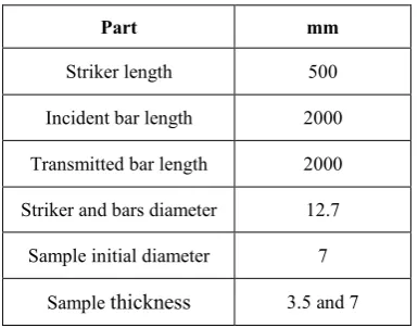
A compression SHPB system was used to determine the dynamic properties of AlSi10Mg. The two long bars (incident and transmitted) were made of maraging 250 steel as well as the striker bar. The dimensions of the system are given in table 1. An air gun was used to accelerate the striker bar. The striker velocity was measured in each experiment and found to be in the range 10-30 m/s. In order to achieve a “clean” incident pressure pulse shape, the striker bar was supported by two air bushings, thus reducing its friction to minimum. The incident, reflected and the transmitted strains were measured by strain gauges (SG) (model EA-06-062 DE-350).
Table 1. SHPB system dimensions.
Part mm
Striker length 500
Incident bar length 2000
Transmitted bar length 2000
Striker and bars diameter 12.7
Sample initial diameter 7
Sample thickness 3.5 and 7
The SG's are mounted with distance of one meter in length symmetrically to the sample. A half Wheatstone bridge was glued on the bars to eliminate the tilt and the other half was glued to a dummy bar to compensate any temperature difference. A total of 38 samples were tested, in four groups: as-built X-oriented, as-built oriented, heat treated (HT) X-oriented and HT Z-oriented. All strain-rate values in this study were calculated as the average strain-rate measured from the reflected pulses. To test the repeatability, each test was repeated under the same conditions at least twice. As will be presented subsequently, the repeatability was
satisfactory and there were no noticed system effects. The relative difference between two results was calculated by:
Relative differencee = 1/N ·ΣN
i=1 (σi(2) – σi(1))/ (σi(2)) (3)
where N is the number of values recorded in a single stress strain curve and σ is the true stress of a single experiment. The relative difference in two tests with the same initial conditions was less than 1%. Furthermore, to ensure that there were no geometrical effects, a comparison was made between two samples with different thicknesses (3.5 and 7 mm). To maintain the strain-rate in both experiments, the striker velocity was adjusted accordingly. Using equation 3, a difference of less than 3% was found between those two experiments, suggesting that the size effect was minor.
3 Samples preparation
The tested samples were machined from rods that were manufactured by the AM-SLM process. The rods were built using EOSINT M280 machine in two different orientations: vertical (Z) and horizontal (X) as present in figure 2. The EOSINT M280 machine is equipped with a 250 by 250 mm building platform with maximum height of 300 mm. Only a virgin of pre-alloyed AlSi10Mg powder with particle size in the range of 20–63 m was used. The laser applied continues power of 400 W with spot size of about 80 m in diameter. The macrostructure of the two built orientations can be seen in figure 3. The thickness of the powder layer prior to melting was 60
m, which led to about 30 m actual thickness after solidification. 67° rotations were made between two consecutive layers. After fabrication, half of the batch underwent a heat treatment (HT, T5- 300°C for 2 hours), in order to investigate its effect on the mechanical properties.
Fig. 3. AlSi10Mg typical macroscopy, before tests: melt pools are seen in the X direction (left) and track segments are seen in the Z direction (right).
4 Results and discussion
In the following section the dynamic mechanical properties of the AM-SLM will be presented for as-built, under heat treatment, different orientation and different strain-rate.
4.1 Heat treatment effect
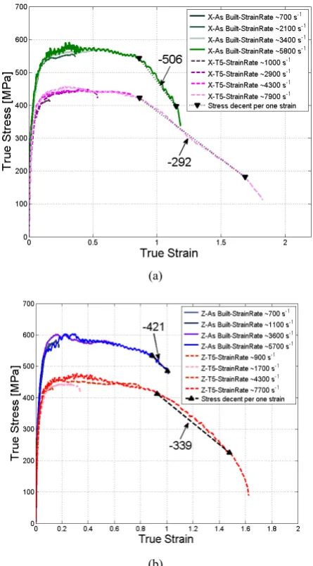
Stress relief is well-known for its effect on the mechanical properties of metals. The HT was selected for its ability to increase ductility, as shown in Tang and Pistorius [9] study. A comparison between samples as-built and after HT is presented in figure 4. In figure 4a, X-oriented samples with different strain-rate are presented while in figure 4b Z-oriented samples with different strain-rate are presented. It is important to emphasize (as explained in the experimental section) that for X-built direction the stress wave is parallel to the sample’s layers and for Z-built direction the stress wave is perpendicular to the sample’s layers. As expected, the yield stress after HT show values of about 20% lower than the yield stress found in the as-built samples in the strain range of 0.15–0.9. It should be noted that the Z-oriented samples for as-built and HT exhibit higher stress values for correlating strain-rate, which was documented also in Rosenthal’s study [4]. The results shown in figure 4 indicate that the stresses that develop in AlSi10Mg for strain-rates of 103 – 8×10³ s-1 for as-built and HT samples in both orientations are within the measurement error. Therefore, AlSi10Mg has no strain-rate sensitivity at this strain-strain-rate range. Those results correlate well with Zaretsky [6] study that suggested that the material starts its strain-rate sensitivity in rates higher than 104 s-1. In strain-rates above 4×10³ s-1, the experimental time is long enough for the true strain to exceed 1. A significant decrease in the stress is observed. This decrease can be related to failure in the sample. As can be seen in figure 4, AlSi10Mg exhibits high values of strain of about 0.8. Since our striker’s length is larger than in some other SHPB systems, we were able to observe these high strains. The values of the slopes for this stress decent per one strain are shown on figures 4 (a) and (b).
4.2 Building Orientation Effect
As AlSi10Mg becomes more popular in the industry, the main goal of this study was to investigate whether or not the building orientation affects the mechanical properties. This investigation is important from an engineering point of view because the manufacturing platform has a limited size (in our case 250 × 250 × 300 mm). Therefore, to additively manufacture larger parts one has to assemble the required part from different smaller parts which can be manufactured using different building orientations. Therefore, it is essential to investigate the stress difference and the deformation at the different built orientations. Figure 5 show 16 true-stress true-strain curves for different samples with strain-rate ranged 7×10² – 3.4×10³ s-1. Significant differences are observed between the Z and X built orientations in the as built samples at a strain range of 0.05 to 0.25. The stress of the Z-oriented is about 10% larger than the X built orientation. In the HT samples this significant difference decreases although it does not diminish. The Z-oriented samples experience 5% higher stress than the X oriented. The observed difference is beyond the measurements statistical error. In all cases, The Z built orientation reaches larger stresses.
(a)
(b)
Fig. 5. True Stress true strain curves of AlSi10Mg for as-built and HT treatment. (a) for X-orientation and (b) for Z-orientation. This phenomenon is seen for the first time in the
present study for AM-SLM. The values are presented in table 2. This stress difference is vanished above strain-rates of 4×10³ s-1. In the study of Zaretsky [6] which was done in a strain-rate of 104 s-1 there is no significant orientation dependency. That observation is in agreement with our results namely, that at high strain rate the orientation dependency is diminished.
It is interesting to note that at low strain-rates (about 10-6 – 1 s-1) there is a negligible effect of the orientation too [4]. According to our results this phenomenon occurs only in a strain-rate range of 103 – 3×10³ s-1. This behaviour is still under investigation.
Table 2. True stress values with standard deviation.
Oriented
direction strain Stress as-built Stress HT
Z 0.1 569±8.5 427±4.8
X 0.1 514±6.7 405±7.8
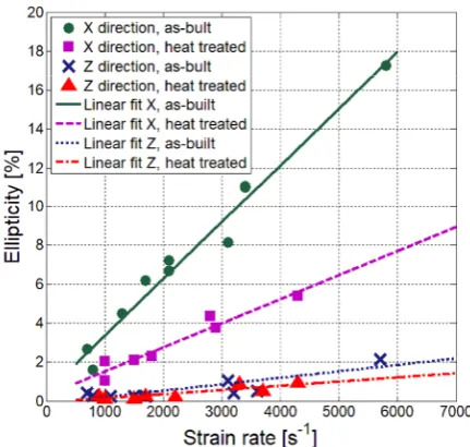
The post-mortem X-oriented samples for as-built and HT did not maintain their original symmetric shape in contrast to the Z-oriented samples. Instead, they became elliptical with two distinguished diameters. The measured maximum and minimum diameters are shown in figure 6. The ellipticity was calculated using equation 4. For the Z-oriented samples the ellipticity is close to zero. However, for the X-oriented samples the ellipticity varied with the strain-rate. In figure 7 the ellipticity with respect to the strain-rate is presented. One should note that there is a significant difference between the as-built and the HT samples.
Ellipticity = [(Dmax - Dmin)/ (Dmax)]·100 (4)
Fig. 6. Schematic drawing of the diameters before and after the impact.
One should bear in mind that the samples experience several impacts during the overall experimental time.
Fig. 7. Schematic drawing of the diameters before and after impact.
5 Conclusion
The mechanical properties of AlSi10Mg alloy at strain-rates of 103–8×10³ s-1 were measured by a SPHB experimental apparatus. It was found that there is a significant difference in the mechanical properties between samples after HT and as-built, as also reported by others. We noted that the built orientation affected the mechanical properties at a strain-rates range of 103– 3×10³ s-1. At higher and lower strain-rates this effect diminished. No strain rate sensitivity was observed in this study.
The anisotropic nature of the samples was determined by the ellipticity of the samples: a noticeable difference was noticed in the deformation behavior of the sample.
The authors would like to thank "Sharon Tuvia (1982)", Nes- Tziona, Israel, for providing the components.
References
1. W.J. Sames, F.A. List, S. Pannala, R.R. Dehoff, and S.S. Babu, Int. Materials Rev., 61(5), 315-360, (2016)
2. N. Takata, H. Kodaira, K. Sekizawa, A. Suzuki, and M. Kobashi, Materials Sci. & Eng. A, 704, 218-228 (2017)
3. D. Apelian, (North American Die Casting Association, 2009)
4. I. Rosenthal, A. Stern, N. Frage, Materials Sci. & Eng. A, 682, 509-517 (2017)
5. H. Asgari, A. Odeshi, K. Hosseinkhani, M. Mohammadi, Materials Letters, 211, 187-190 (2017) 6. E. Zaretsky, A. Stern, N. Frage, Materials Sci. &
Eng. A, 688, 364-370 (2017)
7. W. Chen, B.S. Chen, Split Hopkinson (Kolsky) bar: Design, testing and applications, (Springer Science, 2011)
8. K. T. Ramesh, Springer handbook of experimental solid mechanics, Springer US, 929-960. (2008) 9. M. Tang, P. Pistorius, C. Int. J. Fatigue, 94, 192-201
![Fig. 1. A schematic drawing of laser melting system as described in [3].](https://thumb-us.123doks.com/thumbv2/123dok_us/8040651.1338729/1.595.323.507.426.553/fig-schematic-drawing-laser-melting-described.webp)