Scattering of Non-Diffracting Vortex Electromagnetic Wave
by Typical Targets
Mei Ping Yu*, Yiping Han, and Zhiwei Cui
Abstract—In the field of radar target detection, vortex electromagnetic (EM) wave carrying orbital angular momentum (OAM) has drawn great attention in recent years because of its prospect to improve the capacity of information acquisition. As a typical vortex EM wave, the high-order Bessel vortex beam (HOBVB) has the properties of non-diffraction propagation, small central spot diameter, good direction, and long propagation distance. This study investigates the scattering of non-diffracting HOBVB by radar targets. The mathematical description of the electromagnetic field components of the arbitrarily incident HOBVB are given. The surface integral equations for solving the scattering problems involving typical radar targets are established. The effects by OAM intrinsic mode characteristics on the radar scattering cross section are simulated. This investigation is expected to provide useful guidance for revealing EM scattering mechanism in the OAM domain.
1. INTRODUCTION
Currently, radar information carrier primarily refers to EM wave at microwave band. And information is mainly modulated in time, frequency or polarization domain [1]. When EM beam’s phase wave front has a non-planar structure, its capacity of information transmission and acquisition will be improved by modulating necessary information [2]. Coming from an extension of the concept of optical vortex, vortex beam carrying OAM [3] has drawn great attention in recent years due to its helical structure wave front phase. EM vortex structure of the helical structure front can be described in a rotational phase factor exp(imϕ), whereϕis the azimuth angle around the beam axis andmis the intrinsic value of the orbital angular momentum which is used to describe the OAM states [4]. Different intrinsic value corresponds to a different phase distribution of intrinsic mode. Since the number of OAM mode can be any value, in theory, more information can be modulated by using the same carrier frequency, and the capacity of EM wave in information acquisition can be improved [5]. When target is illuminated by OAM-carrying radio beams, the result is the same as it’s irradiated by traditional plane wave from continuous multiple angles. Then the capacity of the specific spatial diversity of target can be improved. Further integrating radar signals by expanding high-bandwidth, it is expected to achieve more desirable dimensional imaging. As well known, scattering characteristics of target are the bases of radar detection and recognition. The current study mainly focused on frequency, angle and polarization domain [6]. The aim of this paper is to investigate the scattering characteristics of target in OAM domain. With the development of laser shaped beams and the tremendous expansion of their applications, there has been a growing interest in the study of EM scattering by various targets illuminated by non-diffracting beams due to their special characteristics, for instance they can propagate over a characteristic length without spreading and are able to wholly reform at some distance beyond the obstruction as long as the whole beam is not blocked if they encounters an obstruction [7, 8]. Among several possible functional descriptions of OAM modes, the HOBVB, which is strictly a special solution of the Helmholtz equation, have a number of remarkable
Received 5 June 2017, Accepted 14 September 2017, Scheduled 3 October 2017
* Corresponding author: Mei Ping Yu ([email protected]).
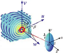
the beam relative to the targets is often arbitrary. For the sake of convenient description, let’s define two Cartesian coordinate systems. The particles are attached to a coordinate system Oxyz, and the incident beam is attached to OBuvw. The beam center OB is located at (x0, y0, z0) in the Cartesian
coordinate system of the targetsOxyz.
J
Figure 1. Geometry of the scattering problem under study.
2.1. Unpolarized High-Order Bessel Vortex Beam
For the description of a Bessel beam, Durnin [10] first gives scalar equation which satisfies the wave equation. An HOBVB is a field of electromagnetic whose amplitude is described by the cylindrical Bessel function of the first kind Jm(·) of orderm. The scalar expression and its intensity in transverse plane of the HOBVB in its own Cartesian coordinate system OBuvw can be described by:
A=A0Jm(krr) exp [i(kww+mφ)] (1)
I =|Jm(krr)|2 (2)
where parameterskr=ksinβ andkw =kcosβ are the transverse and axial wave numbers, respectively, withβ being the half-cone angle of the beam andλbeing the wave length of the beam, which is related to the wave number kas k= 2π/λ. Also, φ= tan−1(v/u) is the phase angle, andr =√u2+v2 is the
radial distance to a point in the transverse plane (u, v).
When the wavelength is much smaller than the size of the central spot of the beam, i.e., kr k, the scalar expression of the HOBVB can provide satisfactory results. Fig. 2 displays the 3-D distribution of intensity for different intrinsic values (m) of the OAM in the OBuv plane with a size of 10.0 mm×10.0 mm. The relevant parameters are β = 25◦ and λ = 1.0 mm. As can be seen from Fig. 2, for the fundamental zero-order (m = 0) Bessel beam, the intensity distribution consists of a series of concentric rings with a bright central core, but for the high-order (m≥1) Bessel vortex beams, their intensity distributions have a dark central core surrounded by concentric rings, and the radius of the inner ring increases with the order.
(a) Intensity (m=0) (b) Intensity (m=1) (c) Intensity (m=2)
Figure 2. 3-D distribution of intensity for different order Bessel beams.
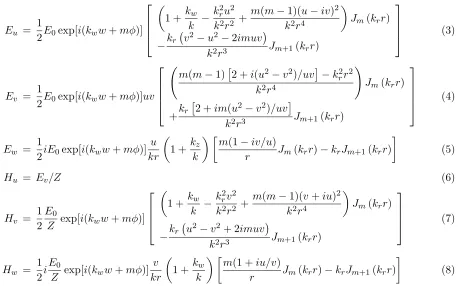
Eu = 1
2E0exp[i(kww+mφ)]
⎡ ⎢ ⎢ ⎣
1 +kw
k −
k2ru2 k2r2 +
m(m−1)(u−iv)2 k2r4
Jm(krr)
−kr
v2−u2−2imuv
k2r3 Jm+1(krr)
⎤ ⎥ ⎥
⎦ (3)
Ev = 1
2E0exp[i(kww+mφ)]uv
⎡ ⎢ ⎢ ⎢ ⎣
m(m−1)2 +i(u2−v2)/uv−k2rr2 k2r4
Jm(krr)
+kr
2 +im(u2−v2)/uv
k2r3 Jm+1(krr)
⎤ ⎥ ⎥ ⎥
⎦ (4)
Ew = 12iE0exp[i(kww+mφ)]u
kr
1 +kz k
m(1−iv/u)
r Jm(krr)−krJm+1(krr)
(5)
Hu = Ev/Z (6)
Hv = 1 2
E0
Z exp[i(kww+mφ)]
⎡ ⎢ ⎢ ⎣
1 +kw
k −
kr2v2 k2r2 +
m(m−1)(v+iu)2 k2r4
Jm(krr)
−kr
u2−v2+ 2imuv
k2r3 Jm+1(krr)
⎤ ⎥ ⎥
⎦ (7)
Hw = 1
2i E0
Z exp[i(kww+mφ)] v kr
1 +kw k
m(1 +iu/v)
r Jm(krr)−krJm+1(krr)
(8)
whereE0 and H0 are the amplitudes of the electric field and magnetic field strength, with Z being the
wave impedance in background medium, respectively. Especially deserving to be mentioned, a parallel translation of the Cartesian coordinatesx=u−x0,y =v−y0, andz=w−z0 is applied to transform
the description of an EM HOBVB in terms of vectors components (Eu, Ev, Ew) and (Hu, Hv, Hw) from its own Cartesian coordinate system OBuvwto that in the Cartesian coordinate system of the target.
2.2. Surface Integral Equation Method
Now we consider the scattering problem involving an arbitrarily shaped target, as shown in Fig. 1. According to the equivalence principle [13], from the surface electric currents, we can evaluate the fields at any position outside the target by calculating the strict scattering field equation:
Esca0 = Z0L0(J) (9)
−Z0t·L0(J) =t·Einc (11) J−n×K0(J) =n×Hinc (12) Here we employ the combined field integral equation (CFIE), which combines the EFIE and MFIE in the following form:
cEFIE +Z0(1−c) MFIE (13)
where the combination parameter c ranges from 0 to 1 and can be chosen to be any value within this range to remove the interior resonance. We have foundc= 0.2 to be an overall good choice according to some studies have been done on the choosing an optimum c[14].
At this point, we use the the MOM to solve the SIE established above numerically [15–18]. In implementation, the most suitable basis functions called RWG basis functions [19] are used, and the equivalent electric currentsJ can be expanded as
J= N
n=1
Jnfn (14)
where N is the total number of edges on the surface of the particle; fn are the RWG basis functions; Jn are the expansion coefficients yet to be determined. Using the standard Galerkin’s method [20], we obtain a full linear system of equations:
[A]{J}={b} (15)
where the elements of matrix [A] and the elements of vector {b} are defined as
Amn = −cZ0
Sfm·L0(fn)dS +Z0(1−c)
Sfm·[fn−n×K0(fn)]dS (16)
bm = c
Sfm·E
incdS−Z
0(1−c)
Sfm·
n×HincdS (17)
The SIE code developed here can simulate scattering electric currents over the triangular surface mesh elements.
Subsequently, as a characteristic value for the scattering of complex target illuminated by arbitrary incident wave, the results to be presented are in terms of the radar scattering cross section (RCS) and three-dimensional (3-D) distribution of the intensity for the scattered electric fields in the far-field region. The radar scattering cross section is defined as [21–23]:
σ= lim r→∞4πr
2 Escafar2
3. NUMERICAL RESULTS
Since the EM scattering of a non-diffracting HOBVB by nonspherical targets has not been reported, no available numerical results can be used for comparison to illustrate the validity of the proposed method. Nevertheless, we can consider a special case, letting m = 0. In this case, the vector expressions of an HOBVB become those of a zero order bessel beam (ZOBB). Now, we consider the EM scattering of an
(a) (b)
Figure 3. Comparison of the DSCSs for a spheroidal particle obtained from the SIE and that from the GLMT: (a)E-plane, (b)H-plane.
(a) (b)
Figure 4. Effects of the order on the RCS: (a)E-plane and (b) H-plane.
m=1 m=2 m=3
Figure 6. 3-D solid model of a aircraft and the discrete model.
(a) (b)
Figure 7. Effects of the ordermon the RCS: (a) E-plane and (b)H-plane.
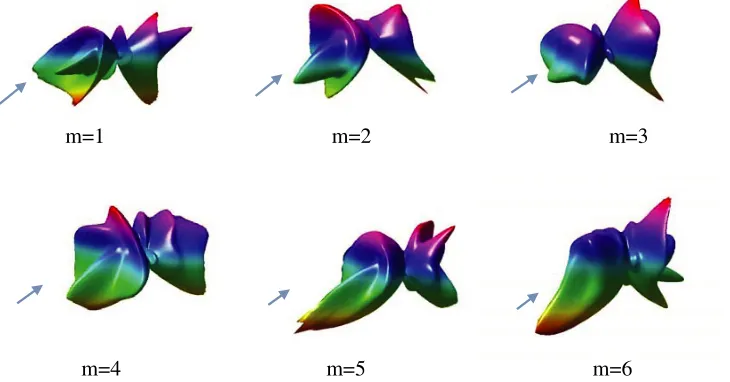
m=1 m=2 m=3
m=4 m=5 m=6
using the proposed SIE. For comparison, the results obtained using the generalized Lorenz-Mie theory (GLMT) are given in the same figure. Excellent agreements are observed between them.
Next, the spheroid considered above is taken as an example, and the effects of the order of the beam on the RCS are analyzed. Fig. 4 shows the effects of the OAM on the RCS distributions for both theE-plane andH-plane. It is found that the RCS decreases as the intrinsic value of the OAM of the beam increases. Fig. 5 also presents the 3-D distribution of the intensity for the scattered fields in the far-field region.
Then the numerical results for the EM scattering of a HOBVB by a certain type of aircraft model are presented. Fig. 6(a) shows the 3-D solid model of an aircraft, and Fig. 6(b) presents the discrete model with about 10834 triangle patches on its surface. Then, we use the parallel MOM to calculate the RCS. Fig. 7 displays the RCS distributions at different intrinsic value of the orbital angular momentum, while Fig. 8 shows the 3D directivity plots of the aircraft for the far-field scattering by a HOBVB with different OAM.
4. CONCLUSION
In summary, the non-diffracting vortex EM Wave by several typical targets has been investigated by using the SIE. The incident unpolarized EM HOBVB is represented by vector expressions in terms of the electric and magnetic fields. As an example, the effects of the OAM intrinsic mode characteristics on the RCS and 3-D plots of the far-field scattering for a spheroid are analyzed. Also the RCS and 3D directivity plots for the far-field scattering for a typical aircraft model illuminated by a HOBVB are presented. These results could be used as a reference for other research on the scattering characteristics and EM scattering mechanism in the OAM domain of complex radar target by non-diffraction vortex beam.
ACKNOWLEDGMENT
This work has been supported by the National Natural Science Foundation of China under grant No. 61675159, and the Nature Science Foundation of Shaanxi Province under grant No. 2016JM1001.
REFERENCES
1. Yao, A. M., and M. J. Padgett, “Orbital angular momentum: Origins, behavior and applications,”
Adv. Opt. Photon., Vol. 3, 161–204, 2011.
2. Swartzlander, G. A. and C. T. Law, “Optical vortex solitons observed in Kerr nonlinear media,”
Phys. Rev. Lett., Vol. 69, 2503–2506, 1992.
3. Franke-Arnold, S., L. Allen, and M. Padgett, “Advances in optical angular momentum,” Laser &
Photon. Rev., Vol. 2, 299–313, 2008.
4. Mitri, F. G., “Arbitrary scattering of an acoustical high-order Bessel trigonometric (non-vortex) beam by a compressible soft fluid sphere,”Ultrasonics, Vol. 53, 956–961, 2013.
5. Dardari, D. and V. Tralli, “High-speed indoor wireless communications at 60 GHz with coded OFDM,” IEEE Transactions on Communications, Vol. 47, No. 11, 1709–1721, 1999.
6. Li, R. X., C. Y. Ding, K. F. Ren, X. E. Han, L. X. Guo, Z. S. Wu, and S. X. Gong, “Scattering of a high-order Bessel beam by a sphere,” 10th International Symposium on Antennas, Propagation
& EM Theory, 833–836, 2012.
7. Durnin, J., J. Miceli, and J. H. Eberly, “Diffraction-free beams,” Phys. Rev. Lett., Vol. 58, No. 15, 1499–1501, 1987.
8. Mitri, F. G., “Acoustic scattering of a high-order Bessel beam by an elastic sphere,” Ann. Phys., Vol. 323, No. 11, 2840–2850, 2008.
15. Ubeda, E., J. M. Tamayo, and J. M. Rius, “Taylor-orthogonal basis functions for the discretization in method of moments of second kind integral equations in the scattering analysis of perfectly conducting or dielectric objects,”Progress In Electromagnetics Research, Vol. 119, 85–105, 2011. 16. Mittra, R.,Computer Techniques for Electromagnetics, Pergamon Press, Oxford, 1973.
17. Gibson, W. C., The Method of Moments in Electromagnetics, Chapman & Hall Taylor & Francis Group, Boca Raton London, New York, 2008.
18. Volakis, J. L. and K. Sertel, Integral Equation Methods for Electromagnetics, SciTech Publishing, Inc., Raleigh, NC, 2012.
19. Rao, S. M., D. R. Wilton, and A. W. Glisson, “Electromagnetic scattering by surfaces of arbitrary shape,” IEEE Trans. Antennas Propag., Vol. 30, 409–418, 1982.
20. Harrington, R. F., Field Computation by Moment Methods, Macmillan, New York, 1968.
21. Taylor, J. M., “On the concept of near field radar cross section,”Proceedings of IEEE Transactions
on Antennas and Propagation Society International Symposium, 1172–1175, IEEE, Montreal,
Quebec, Canada, 1997.
22. Taylor, J. M., “On the concept of near field radar cross section,”IEEE Microwave Magazine, Vol. 8, No. 2, 77–82, April 2007.