Optimization Technique for Improving the Performance of PV
based Self-Lift Luo Converter
K.Raghuveer & Dr.Moinuddin K Syed
M.Tech.,(Ph.D)
Research Scholar Department of Electrical Engineering, Himalayan University,Itanagar, India
[email protected]
Professor EEE Department SCIENT,Hyderabad,India
Abstract─ The paper presents a self-lift Luo converter for photo-voltaic (PV) based application. Proposed Luo converter exhibits high-gain characteristics yielding high output DC level required for PV applications. The photovoltaic cells are operated at their maximum power point using Maximum Power Point Tracking (MPPT) techniques. Illumination, temperature, radiation intensity are some of the factors that can influence the maximum power point. Particle swarm optimization (PSO) based Maximum Power Point Tracking (MPPT) is employed with PID controller to track the maximum power from the PV cell. Duty cycle for Luo converter is generated by sensing the panel voltage, current and the corresponding power values. Simulation analysis is presented using MATLAB/SIMULINK software for PV with Luo converter with PSO technique.
Keywords ─ PV module, Maximum power point tracking, PSO ,Super-lift Luo converter.
I.INTRODUCTION
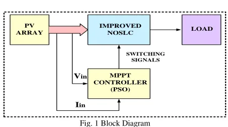
An Analysis is done on basic DC-DC converter, which is used in high voltage applications, to implement the Improved Negative Output Super-Lift Luo Converter. By using VL technique The NOSLC converter produces high negative voltage. By applying this VL technique effectively to increases the output voltage and overcomes the results of parasitic elements. . Therefore, from source voltage these DC/DC converters produces higher output voltage with greater efficiency and a simple structure. The block diagram describes that the supply voltage is fed to the INOSLC and then the output from it is given to the load. By comparing the as the output from the converter with the reference voltage an error is generated as the output.This output is fed to the controller block. As result the controller produce the duty ratio. To generate the required pulse for the operation of the system this duty ratio is given to the switch. The PhotoVoltaic systems arise with a problem of poor efficiency, to overcome this disadvantage “Maximum Power Point Tracking (MPPT)”.method is used.
PV ARRAY
IMPROVED
NOSLC LOAD
MPPT CONTROLLER
(PSO)
Vin
Iin
SWITCHING SIGNALS
Fig. 1 Block Diagram
A variety of maximum power point tracking (MPPT) method is developed. The methods vary implementation complexity, sensed parameters, range of operation, convergence speed and cost, popularity and their application. Particle Swarm Optimization is a combinatorial method implied with PID controller. This MPPT method helps in tracking maximum power by sensing panel voltage and current.
II. PV CELL MODEL AND CHARACTERISTICS
PV CELL MODEL
Photo voltaic is method of generating electrical power by converting solar power into direct current electricity using semiconductors that exhibits the photo voltaic effect. Photovoltaic power generation employs solar panels composed of a number of solar cells containing a photovoltaic material. The equivalent circuit of PV module is given by,
LOAD
Rsh
Rs SOLAR CELL
+
The intrinsic shunt resistance ,Rsh and series resistance, Rsare used in PV cell . The current source represents the cell photo current. Usually the value of Rsh is muchgreater than the value of Rs.
Equations of pv module is modeled mathematically is given by, Module photo-current (𝐈𝐏𝐡)
𝐼
𝑝ℎ=
[𝐼
𝑠𝑐+
𝑘
𝑖(T-
𝑇
𝑟)]X
Where X is the module illumination Tr is the
reference temperature Isc is the short circuit current
of the PV module at reference temperature, ki is the
short circuit current temperature co-efficient is the module operating temperature.
Module reverses saturation current-Ir
𝐼
𝑟=
𝐼𝑠𝑐[𝑒𝑥𝑝( 𝑞𝑉𝑜𝑐
𝑁𝑠𝑘𝐴𝑇)−1]
Where Ns is the no of cells connected in series, Voc is the open circuit voltage, A is the ideality factor, q is the electron charge, k is the Boltzman constant. The Module saturation current Io varies with the cell temperature, which is given by
𝐼
𝑠= 𝐼
𝑟𝑠(
𝑇
𝑇
𝑟)
3
∗ 𝑒
((𝑞𝐸𝑔
𝐾𝐴)∗(1 𝑇⁄ −1 𝑇𝑟 ⁄ ))
Eg is the band gap for silicon. The current output of pv module is
𝐼𝑝𝑣= Iph− Is∗ [
𝑒^(𝑞(𝑉𝑝𝑣 + 𝐼𝑝𝑅𝑠))
𝑁𝑠𝐴𝐾𝑇 − 1]
Fig 3 Modeling of Solar Panel
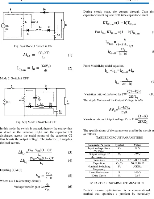
III.IMPROVED NEGATIVE OUTPUT SUPER-LIFT LUO CONVERTER
The basic converter shown in Fig. 4 is NOSLC.The circuit consists of a MOSFET switch S, Diodes D1, D2, Inductor L1,Capacitors C1, C2 and load resistance R .From the above two figures it is observed that to the NOSLC circuit,the modifications is brought to the INOSLC circuit by adding an additional inductor and a diode to it.
+ - DC
L1
D1 D2 C2
C1
R
Fig.4 Basic NOSLC Circuit
+ - DC
L1
D1 D2 C2
C1
R D3
L2 20V
0.01mH
0.01mH 30µf
10µf 100e
Fig. 5 Circuit Diagram of INOSLC
ANALYSIS OF INOSLC
The switching topologies of the proposed circuit in fig. 2 is shown in fig. 3 and fig. 4 as follows.
Mode 1: Switch S ON
+
- DC
L1
D1
D2
C2 C1
R D3
L2 20V
S
+
+
-+
-Fig. 6(a) Mode 1 Switch is ON
∆𝐼
𝐿1=
(VinkT)
L1
(1)
I
C2,on= I
0=
(CdV0)dt
(2)
Mode 2: Switch S OFF
+
- DC
L1
D1 D2
C2 C1
R D3
L2 S
+
+
-+
-+
-0.01mH
0.01mH 30µf
10µf 100e
Fig. 6(b) Mode 2 Switch is OFF
In this mode the switch is opened, thereby the energy that is stored in the inductor L1,L2 and the capacitor C1 discharges across the nodal points of the capacitor C2 thus boosts the output voltage. The inductor L1 supplies the load current.
∆I
L1=
(V0−VinL)(1−k)T 1(3)
∆I
L2=
(V0−Vin)(1−k)TL2
(4)
Equating (1) &(3)
V
0=
2Vin1−k
(5)
Where n = 1 (elementary circuit)
Voltage transfer gain G=𝑉0
𝑉𝑖𝑛
(6)
During steady state, the current through C2on time
capacitor current equals C2off time capacitor current.
K
T
ic2on=
(1 − k)T
ic2offFor
I
C1, KT
ic2on=
(1 − k)T
ic1off(7)
I
C1on=
𝑘(1−𝑘)𝐼𝑐1𝑜𝑓𝑓
i
C2off=
𝑘𝐼0(1−𝑘)
(8)
From ModeII,By nodal equation,
I
L1+
I
L2=
I
C2off+
I
0I
L1=
I02(1−k)
(9)
Variation ratio of Inductor IL1
ɛ=
k(1−k)R
2GfL
1(10)
The ripple Voltage of the Output Voltage is ΔVo
∆V
0=
(1−k)V0fC2R
Variation ratio of Output voltage Vo is
ɛ =
(1−k)
2fRC
2The specifications of the parameters used in the circuit are as follows
TABLE I.CIRCUIT PARAMETERS
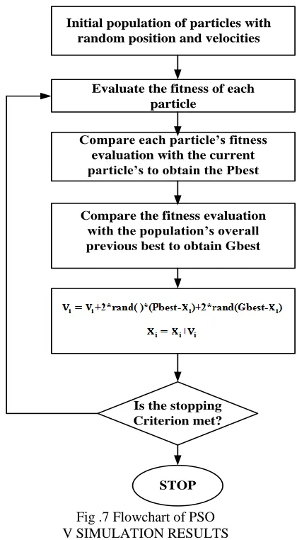
IV PARTICLE SWARM OPTIMIZATION
improves a candidate solution with regard to a given measure of quality. In this paper, to be realized as a MPPT algorithm, the particle position in PSO represents the duty-cycle, the velocity is the step-size of the duty-cycle, and the objective function is maximizing the converter power.
A . PSO WITH PI CONTROLLER
PSO with PID controller is method to extract the maximum power from photovoltaic PV Panel subject to partial shading. In this paper, PSO based method used for tracking maximum power point from non-linear PV characteristics of PV Panel. PID controller adjust the performance of the system by reaching reference value in less time and minimum steady state error. The PSO based optimization deals with different disturbances that can affect the normal operation of PV Panel. The mathematical expression for velocity update for PSO
V
i(k+1)= W
i∗ V
ik+ C
1xR
1∗ (pbest − X
ik) +
C
2∗ R
2∗ (gbest − X
ik)
(11)
The improved velocity updated for the PSO
V
i(k+1)= W
i∗ V
ik+ C
1∗ R
1∗ (pbest − X
ik)
+C
2∗ R
2∗ (gbest − X
ik)
+C
2∗ R
L∗ (gbest − X
ik)
(12)
Where
V
ikCurrent velocity of particle i at iteration k,
V
i(k+1)) updated velocity of particle i,
Wi different inertia weight of particle i,
C
1, C
2,..
C
Lpositive constants,X
ikcurrent position of particle i at inertia k,
R
1,
R
2, ...
R
L random number between 0 and 1L positive number (L = 1 … L)
Initial population of particles with random position and velocities
Evaluate the fitness of each particle
Compare each particle’s fitness evaluation with the current particle’s to obtain the Pbest
Compare the fitness evaluation with the population’s overall previous best to obtain Gbest
Is the stopping Criterion met?
STOP
Fig .7 Flowchart of PSO V SIMULATION RESULTS
The INOSLC with load resistance 100Ω, when fed with 12V DC input from PV Panel with the duty ratio of 67% gives the output voltage of -75V. The DC output voltage produced by PV module depends on variation in irradiation, intensity and temperature. The PV panel gives5.5A and 12V for Irradiation of 650W/m2.The power input to the converter is 60W
Fig.8 INOSLC connected to PV Panel with MPPT Tracking(PSO-PID controller)
Fig.9 Input Voltage to the converter
Fig. 10 Volatge across the Capacitor C1
Fig. 11 Volatge across the Capacitor C2
Fig.12 Output current of the converter
Fig .13 Output Voltage from the converter
Fig. 14 Power at different radiations TABLE II. Power at different radiations
X. CONCLUSION
technique (PSO with PID controller).This method has achieve steady state in less time and has high convergence rate. PSO is combinatorial optimization used with PID controller. With less number of components the proposed converter produces same output as re-lift converter .
REFERENCES
[1] Fang Lin Luo, Senior Member, IEEE, and Hong Ye, Member, IEEE, “Negative Output Super-Lift Converters”,IEEE Transactions on Power electronics, vol.18,no.5,September2003.
[2] Fang Lin Luo, Hong Ye, “Advanced DC-DC converters”, CRC Press. [3] F. L. Luo and H. Ye, "Negative Output Super-Lift Luo-Converters," Proceedings (CD-ROM) of IEEE International Conference PESC’03, Acapulco, Mexico, June 15-19,2003,pp.1361-1366.
[4] V. Chamundeeswari ,R. Seyevhai ,A. Arul Robin ,”Stabilization and Robustification of Negative Output Super-Lift Luo Converter using Sliding Mode control Approach”,International Journal of Advances inEngineeringand Technology,May 2012,ISSN:2231-1963.
[5]YefimBerkovich,BorisAxelrod,RotemMadar,Avra hamTwina,”ImprovedLuoConverteModificationswitc h increasing voltageratio”,International Journal on IET Power electronics,ISSN 1755-4535
[6]Kennedy,J.andEberhart,“ParticleSwarmOptimizati on”publishedinyear1995.
[7]Selvapriyanka.P,Vijayakumar.G.“ParticleSwarm Optimization Based MPPT for PV System under Partial Shading Conditions” published in year 2014. [8] Vijay kumar Gali, Hemakumar.K., “SEPIC converter based Photo voltaic system with Particle swarm Optimization MPPT” published in international IEEE Conference .
[9] Ze Cheng, Hang Zhou, Hongzhi Yang , “Research on MPPT control of PV system based on PSO algorithm”, International Journal on IET Power electronics,2010.
[10]Brunton, S. L. M. and al. 2010. Maximum Power Point Tracking forPhotovoltaic Optimization Using RippleBased Extremum Seeking Control. IEEE Trans. On Power Electronics, Vol. 25, 2531-2540. [11] Kashif Ishaque,Zainal Salam,Muhammad Amjad and Saad Mekhilef, “Improved PSO – Based MPPT for PV with Reduced steady state oscillation” ,IEEE Transactions on Power Electronics, 2012. [12] Esram, T. and Chapman, P. (2007) “Comparaison of Photovoltaic Array Maximum Power Point Tracking Techniques’’, IEEE Trans. On
EnergyConversion.
[13] Li Xu-zhou, Yu Fei, Wang You-bo, “PSO Algorithm based online Self Tuning of PID Controller’’, International Conference on Computational Intelligence and Security, 2007. [14] Alrijadjis, Tanaka K, “Self-tuning PID controller based on PSO-RIW for ultrasonic motor’’, International Journal of Engineering Innovation and
Management, Vol.2 (2012), pp.3340.