University of Southern Queensland
Faculty of Engineering & Surveying
PHD DISSERTATION
WIRELESS NETWORK CODING FOR
MULTI-HOP RELAY CHANNELS
Gengkun Wang
Student Number: 0061003974
Principal Supervisor A/Prof. Wei Xiang
Co-Supervisor A/Prof. Paul Wen
Future wireless communication systems are required to meet growing demands for high spectral efficiency, low energy consumption and high mobility. The advent of wireless network coding (WNC) has offered a new opportunity to improve network throughput and transmission reliability by exploiting interference in intermediate relays. Combined with network coding and self-information cancelation, WNC for two-way relay channels (TWRCs) has come to the forefront.
This dissertation focuses on exploiting WNC in multi-hop two-way relay chan-nels (MH-TRCs). Particularly, a multi-hop wireless network coding (MH-WNC) scheme is designed for the generalized L-node K-message MH-TRC. Theoret-ical studies on the network throughput and performance bounds achieved by the MH-WNC scheme with different relaying strategies (i.e., amplify-and-forward (AF) and compute-and-forward (CPF)) are carried out. Furthermore, by intro-ducing different numbers of transmission time intervals into the MH-WNC, a multiple-time-interval (Multi-TI) MH-WNC is proposed to determine an optimal MH-WNC which can achieve the best outage performance for all-scale MH-TRCs. Finally, this study extends the research on WNC one step forward from two-user networks to multi-user networks. An extended CPF joint with a dominated so-lution for maximizing the overall computation rate is proposed for the multi-way relay channel (mRC) in the last chapter.
re-ii
I certify that the ideas, designs and experimental work, results, analyses and conclusions set out in this dissertation are entirely my own effort, except where otherwise indicated and acknowledged.
I further certify that the work is original and has not been previously submitted for assessment in any other course or institution, except where specifically stated.
——————————— / /
Gengkun Wang, Candidate
——————————— / /
A/Prof. Wei Xiang, Principal supervisor
——————————— / /
Acknowledgments
First, I would like to express my deepest gratitude to A/Prof. Wei Xiang, my principal supervisor for his endless commitment to directing the research and invaluable guidance. Without his continuous support, this thesis would not have been completed.
I am also thankful to Prof. Jinhong Yuan from UNSW, for his instructive discussions and constructive suggestions to my thesis. I would also like to thank A/Prof. Peng (Paul) Wen, my associate supervisor, for his support during my PhD research.
I would like thank the Chinese Scholarship Council for supporting my study at USQ during these three years. In addition, a special thank to all my friends and colleagues at USQ.
Last but no least, I would like to dedicate this work to my parents. I am greatly indebted to them for their unconditional support, love and encouragement.
Gengkun Wang
University of Southern Queensland
The following publications were produced during the period of candidature:
[1] Gengkun Wang, Wei Xiang, Jinhong Yuan, and Tao Huang, ”Outage per-formance of Analog Network Coding in Generalized Two-Way Multi-Hop Net-works,” in Proc. IEEE Wireless Communications and Networking Conference, Cancun, Mexico, Mar. 2011, pp. 759-764.
This paper was awarded the Best Paper Award by IEEE WCNC 2011, which is one of world’s three most prestigious conferences in communication technolo-gies.
[2] Gengkun Wang, Wei Xiang, Jinhong Yuan, and Tao Huang, ”Outage Anal-ysis of Non-Regenerative Analog Network Coding for Two-Way Multi-Hop Net-works,” IEEE Commun. Lett., vol. 15, pp. 662 - 664, May 2011.
The work in the paper is presented in Chapter 4.
[3] Gengkun Wang, Wei Xiang, and Jinhong Yuan, ”Multi-Hop Compute-and-Forward for Generalized Two-Way Relay Channels,” accepted byTrans. Emerg-ing Tel. Tech. (formerly known as European Transactions on Telecommunica-tions (ETT)).
The work in the paper is presented in Chapter 5.
[4] Gengkun Wang, Wei Xiang, and Jinhong Yuan, ”Outage Performance for Compute-and-Forward in Generalized Multi-Way Relay Channels,” IEEE Com-mun. Lett., vol. 16, pp. 2099 - 2102, Dec 2012.
Contents
Abstract i
Acknowledgments iv
List of Publications v
List of Figures ix
List of Tables xiii
Acronyms & Abbreviations xv
Chapter 1 Introduction 1
1.1 Motivations . . . 2
1.2 Contributions . . . 5
1.3 Organization . . . 7
Chapter 2 Background 9 2.1 Relay Networks . . . 9
2.2 Network Coding . . . 10
2.3 Wireless Network Coding . . . 12
2.3.1 Analog Network Coding . . . 14
2.3.2 Physical-Layer Network Coding . . . 16
2.3.3 Compute-and-Forward . . . 17
2.4 Other Recent Work . . . 20
Chapter 3 Wireless Network Coding for Multi-Hop Two-Way Re-lay Channels 23 3.1 Introduction . . . 23
3.2 Related Work . . . 24
3.3 System Model . . . 26
3.3.1 Message Exchange Pattern . . . 26
3.3.2 Communication Delays . . . 28
3.4.1 Straightforward Scheme . . . 29
3.4.2 Optimized Scheme . . . 30
3.5 Wireless Network Coding . . . 31
3.6 Simulation Platform . . . 36
3.7 Summary . . . 40
Chapter 4 Analog Network Coding for Non-Regenerative Multi-Hop Two-Way Channels 43 4.1 Introduction . . . 43
4.2 Related Work . . . 44
4.3 System Model . . . 46
4.3.1 Non-Network Coding . . . 47
4.3.2 Multi-Hop Analog Network Coding . . . 49
4.4 Received SNR . . . 51
4.4.1 Forward Recursive Approach . . . 52
4.4.2 Backward Recursive Approach . . . 55
4.5 End-to-End SNR . . . 58
4.5.1 Upper Bound . . . 59
4.6 Outage Probability . . . 64
4.7 Maximum Sum-Rate . . . 66
4.8 Effective Network Throughput . . . 67
4.9 Numerical Results . . . 69
4.10 Summary . . . 73
Chapter 5 Compute-and-Forward for Regenerative Multi-Hop Two-Way Channels 75 5.1 Introduction . . . 75
5.2 Related Work . . . 77
5.3 System Model . . . 78
5.4 Computation Rate . . . 80
5.5 Finding the Best Coefficient Vector . . . 81
5.6 Recovering Messages . . . 82
5.7 Outage Probability . . . 85
5.7.1 Non-Network Coding . . . 86
5.7.2 Multi-Hop Compute-and-Forward . . . 87
5.8 Effective Network Throughput . . . 91
5.9 Numerical Results . . . 91
viii CONTENTS
Chapter 6 Optimal Wireless Network Coding for Multi-Hop
Two-Way Relay Channels 97
6.1 Introduction . . . 97
6.2 Problem Statement . . . 98
6.3 Assumptions . . . 99
6.4 System Model . . . 101
6.5 Methodologies . . . 103
6.5.1 Analog Network Coding . . . 105
6.5.2 Compute-and-Forward . . . 113
6.6 Numerical Results . . . 116
6.6.1 Network Throughput . . . 116
6.6.2 Average Received SNR . . . 118
6.6.3 Outage Probability . . . 119
6.7 Summary . . . 127
Chapter 7 Compute-and-Forward for Generalized Multi-Way Re-lay Channels 131 7.1 Introduction . . . 131
7.2 Related Work . . . 132
7.2.1 Finite-Field Network Coding . . . 133
7.2.2 Compute-and-Forward for Multi-Way Channels . . . 134
7.3 System Model . . . 135
7.4 Computation Rate . . . 136
7.5 Outage Probability . . . 140
7.5.1 Non-Network Coding . . . 141
7.5.2 Compute-and-Forward . . . 142
7.6 Numerical Results . . . 143
7.6.1 Finite-Field Network Coding . . . 143
7.6.2 Compute-and-Forward . . . 145
7.7 Summary . . . 150
Chapter 8 Conclusion 153 8.1 Future Work . . . 154
2.1 The butterfly example. . . 11
2.2 A single relay two-way relay channel. . . 13
2.3 Traditional straightforward scheme. . . 13
2.4 Network Coding. . . 14
2.5 Analog network coding. . . 15
2.6 Signal constellation of the received signal at the relay node. . . 16
2.7 Channel decoding network coding. . . 17
2.8 Nested lattice. . . 19
2.9 A simple example of compute-and-forward. . . 19
3.1 The L-node K-message multi-hop two-way relay network. . . 26
3.2 Symmetrical exchange pattern. . . 27
3.3 Non-symmetrical exchange pattern. . . 27
3.4 The straightforward scheme for the MH-TRC. . . 29
3.5 The optimized scheme for the MH-TRC. . . 31
3.6 Wireless network coding for the L-node K-message MH-TRC. . . 32
3.7 Transmission scheme of WNC for the 5-node 2-message MH-TRC. . . 33
3.8 Grid charts of the transmission pattern of MH-WNC for different scale MH-TRCs. . . 39
4.1 The L-node K-message multi-hop two-way relay network. . . 46
4.2 Propagation paths ofw1 2 in 6 time slots. . . 53
4.3 The number of propagation paths to each node. . . 54
x LIST OF FIGURES
4.5 End-to-end SNR for the 5-node 2-message MH-TRC. . . 60
4.6 End-to-end SNR versus the number of messages for different scale MH-TRCs. . . 61
4.7 The upper bound end-to-end SNR versus the number of nodes. . . 62
4.8 Outage probability for the 5-node 2-message MH-TRC. . . 69
4.9 Outage probability versus the number of nodes for the generalized MH-TRC. . . 70 4.10 Effective network throughput for the 5-node 2-message MH-TRC. 71
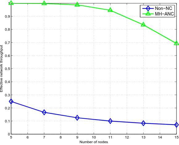
4.11 Effective network throughput versus the number of nodes for the generalized MH-TRC. . . 71
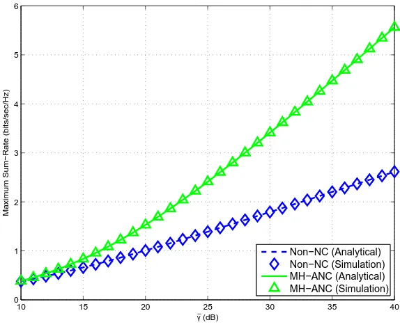
4.12 Maximum sum-rate for the 5-node 2-message MH-TRC. . . 72
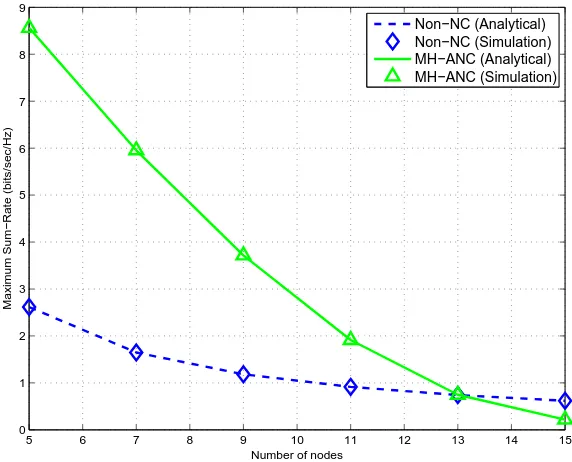
4.13 Maximum sum-rate versus the number of nodes for the generalized MH-TRC. . . 73
5.1 The L-node K-message multi-hop two-way relay network. . . 79
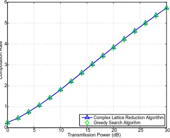
5.2 Maximized computation rate obtained by two different algorithms. 83
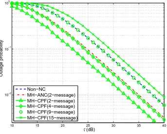
5.3 Outage probability versus the average SNR per hop for the 5-node MH-TRC. . . 92
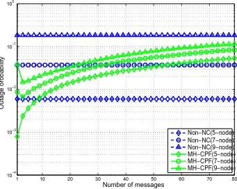
5.4 Outage probability versus the number of messages for the general-ized MH-TRC. . . 93
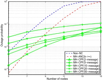
5.5 Outage probability versus the number of nodes for the generalized MH-TRC. . . 94
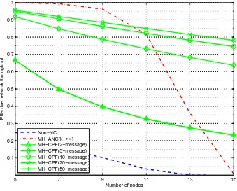
5.6 Effective network throughput versus the number of nodes for the generalized MH-TRC. . . 95
6.1 The L-node K-message multi-hop two-way relay network. . . 101
6.2 Grid chart for the transmission scheme of the 11-node 3-message MH-TRC with 4-TI MH-WNC. . . 102
6.3 Noise propagation model in the 5-node 3-message MH-TRC with 2-TI MH-WNC. . . 105
6.4 Binary tree structure for Figure 4.2. . . 106
6.6 Network throughput versus the number of time intervals for differ-ent scale MH-TRCs. . . 117 6.7 Network throughput versus the number of nodes for the MH-ANC
schemes with different time intervals. . . 117 6.8 Average received SNR versus the number of messages for different
scale MH-TRCs. . . 118
6.9 Average received SNR versus the number of nodes for the MH-ANC schemes with different number of time intervals. . . 119 6.10 Outage probability versus the number of messages for different
scale MH-TRCs. . . 120 6.11 Outage probability versus the number of time intervals for different
scale MH-TRCs. . . 121 6.12 Outage probability for the optimal MH-ANC scheme versus the
number of nodes. . . 123 6.13 Outage probability versus the number of messages for different
scale MH-TRCs. . . 124 6.14 Outage probability versus the number of time intervals for different
scale MH-TRCs. . . 126 6.15 Outage probability versus the number of nodes for the MH-CPF
schemes with different time intervals. . . 127 6.16 Outage probability versus the number of nodes for the optimal
MH-CPF scheme. . . 128
7.1 The multi-way relay channel. . . 135 7.2 Compute-and-forward for the multi-way relay channel. . . 137 7.3 Computation rates versus the average SNR in different scale mRCs. 140 7.4 Outage probability versus the average SNR for the single relay
TWRC. . . 144 7.5 Outage probability versus the number of users for the mRC. . . . 144 7.6 Outage probability versus the target end-to-end rate for the single
relays TWRC. . . 145 7.7 Outage probability versus the target end-to-end rate for the 5-user
xii LIST OF FIGURES
7.8 Outage probability versus the average SNR for the single relay TWRC. . . 147 7.9 Outage probability versus the average SNR for the mRC. . . 148 7.10 Outage probability versus the number of users for the mRC. . . . 148 7.11 Outage probabilities versus the number of users and mean SNR
for the mRC. . . 149 7.12 Effective network throughput versus the number of users for the
2.1 PNC mapping. . . 16
3.1 Transmission events of WNC for the 5-node 2-message MH-TRC. . . 34 3.2 Transmission events of MH-WNC in the L-node K-message
MH-TRC (2K−1< L−1). . . 35 3.3 Different transmission schemes for the generalizedL-nodeK-message
MH-TRC . . . 40
Acronyms & Abbreviations
AF Amplify-and-forward ANC Analog network coding
AWGN Additive white Gaussian noise BER Bit-error-rate
BPSK Binary phase-shift keying BS Base station
BSC Binary symmetric channel CDMA Code division multiple access CDNC Channel decoding network coding CF Compress-and-forward
CPF Compute-and-forward CSI Channel state information DF Decode-and-forward EF Estimate-and-forward
FDMA Frequency division multiple access FFNC Finite field network coding
GF Galois field
LDPC Low-density parity-check LLL Lenstra-Lenstra-Lovsz LNC Linear network coding LTE Long-term evolution MAC Multiple-access channel
MIMO Multi-input multi-output ML Maximum likelihood mRC Multi-way relay channel MS Mobile station
NC Network coding
Non-NC Non-network coding P2P Peer-to-peer
PNC Physical-layer network coding QPSK Quadrature phase-shift keying RA Repeat accumulate
RLNC Random linear network coding SNR Signal-noise-ratio
Chapter 1
Introduction
Wireless communications are increasingly dominating communication tech-nologies in their various forms. They provide the advantages of mobility, global internet connectivity, distributed sensing, and so on. Future mobile and wireless communication systems are required to meet the needs, requirements and inter-ests of users and society as a whole [1]. This will require an increase in spectral efficiency, energy consumption and mobility far beyond those of second or third generation systems.
Much research has been carried out to enhance the spectral efficiency and data rate of next-generation wireless communication systems. Among all these approaches, relay-based wireless communication systems have attracted a great deal of attention thanks to their potential in extending cell coverage and reducing power consumption [2]. In the last few decades, multi-hop networks, such as wire-less sensor networks [3], wirewire-less mesh networks [4], mobile ad hoc networks [5], vehicular ad hoc networks [6], have emerged as promising approaches to provide more convenient wireless communications due to their extended cover range, easy deployment and low costs.
There are a number of scenarios where the LTE relay will be advantageous, such as increasing network density, network coverage extension, and rapid network roll-out. However, despite these advantages, multi-hop wireless relay communi-cations require an increase of time slots to transmit data in a multi-hop man-ner [11]. Most significant of these is the time resource. For example, in a two-hop relay network, two time slots are required to transmit a message via the relay. In wireless multi-hop relay communications, information is conveyed through a se-ries of intermediate relays in a conventional hop-by-hop and message-by-message manner, which limits the network throughput, and thus the data rate of the system.
Recently, the advent of network coding (NC) has offered a new opportunity to improve network throughput and transmission reliability by exploiting interfer-ence in intermediate relays. The concept of NC was originally introduced in [12] in 2000, when a simple but important discovery was made. It was observed that re-lays can not only forward but also combine the incoming messages for generating the message on the outgoing links. The idea was first used in wired networks, and then exploited to wireless networks as wireless network coding (WNC) [13–15].
This study focuses on exploiting WNC in hop relay channels and multi-way relay channels, along with a generalized transmission scheme and theoretical studies. The research outcome of this project can be further implemented to improve the network throughput, outage performance and data rate of next-generation mobile and wireless communication systems.
In the next sections, the motivations of this project, and the primary contri-butions in this dissertation are presented.
1.1
Motivations
1.1 Motivations 3
access channels [21], and multi-cast channels [22]. The performance (including outage probability, bit-error-rate (BER) and maximum sum-rate) of WNC in the single relay TWRC has been widely studied [23–26].
Multi-hop two-way relay networks are wireless networks using two or more wireless hops to exchange messages between two end users. These can be con-sidered as the generalized TWRC. The use of time or frequency in this type of network is different from that of single-hop networks because the time or fre-quency that each hop uses generally does not overlap and interfere. Messages are transmitted hop-by-hop in the multi-hop network, causing delays [27, 28] and reducing the spectrum efficiency of message delivery. The traditional hop-by-hop and message-by-message transmission scheme suffers from severe low spectrum efficiency with the increased number of nodes and messages.
Inspired by the significant improvement of WNC in network throughput in the canonical single relay TWRC, this study exploits WNC into the generalized multi-hop two-way relay channel (MH-TRC) to improve the spectrum efficiency and reduce communication delays. Moreover, according to different strategies applied at the relay, WNC can be categorized into analog network coding (ANC) [29, 30] and physical-layer network coding (PNC) [20]. Therefore, the MH-WNC schemes corresponding to the non-regenerative and regenerative MH-TRCs are designed in this research. The performance of the proposed MH-WNC schemes will be analyzed to demonstrate their superiority to the non-network coding (Non-NC) scheme.
of the network, thus improving the outage performance.
The work published in [35] and [36] showed that the multi-hop wireless net-work coding (MH-WNC) scheme with fixed two transmission time intervals is unable to outperform Non-NC for all-scale MH-TRCs, i.e., the multi-hop ana-log network coding (MH-ANC) [35] can only outperform Non-NC in small scale MH-TRCs, while the multi-hop compute-and-forward (MH-CPF) [36] has better outage performance than Non-NC in the MH-TRCs with a large number of nodes. In view of this fact, by generalizing the number of transmission time intervals, a Multi-TI MH-WNC scheme is proposed to investigate the relationship between the number of time intervals and outage performance. The aim of this work is to determine an optimal MH-WNC scheme which can achieve the best outage performance for all-scale MH-TRCs.
On the application of WNC to wireless relay channels, the two-user two-way relay channel is the simplest and most popular network. However, when extending the two-user case to the multi-user case, most exiting WNC schemes are not directly applicable (such as ANC, “standard” PNC). The proposed CPF in [31] offered a solution for a reliable WNC in multi-user multi-relay networks, where the relay can decode successive linear equations and pass them to the destination. In view of this fact, this research extends the original CPF to multi-user relay networks, such as the multi-way relay channel (mRC).
The idea of the mRC was first introduced by Gunduz et al in [37], in which multiple users exchanged messages with the help of one relay terminal. Tradi-tionally, the relay conveys seperate messages for each pair of users. For example, the relay conveys the message from user U1 to user U2 in the first two time slots,
then convey the message from user U2 to userU1 in the next two time slots, and
1.2 Contributions 5
joined with a novel dominated solution will be designed to realize the application of CPF in the mRC and improve the outage performance.
1.2
Contributions
The key idea underlying this design is to extend wireless network coding from the canonical single relay two-way relay network and MAC to hop and multi-user relay-based wireless networks. This project proposes new designs of WNC to achieve higher performance in the MH-TRC, and further the mRC. Specifically, the contributions in this project can be summarized as follows:
• Wireless Network Coding for Multi-Hop Two-Way Relay Net-works: A general MH-WNC scheme for the generalizedL-nodeK-message MH-TRC is designed. It is proven to significantly improve the network throughput compared to the Non-NC scheme. Specifically, the transmis-sion scheme is generalized with detailed transmistransmis-sion events at each node in different time slots. The transmission pattern is presented by a designed grid chart in Chapter 3.
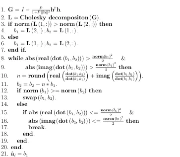
• Multi-Hop Compute-and-Forward: The MH-CPF scheme, where the CPF scheme is applied at relay nodes, is analyzed in Chapter 5. The sim-ilar recursive approaches for deriving the received SNR in the MH-ANC is designed to obtain the received linear combinations at the user nodes to overcome the complexity issue when the numbers of nodes and messages are large. Moreover, a two-dimension complex lattice reduction algorithm is designed to find the best coefficients that maximizes the computation rate. The outage probabilities for both Non-NC and MH-ANC schemes are derived. The numerical results demonstrate that the proposed MH-CPF has better outage performance than Non-NC in large scale MH-TRCs.
• Optimal Multi-Hop Wireless Network Coding. The Multi-TI MH-WNC scheme is proposed in Chapter 6. To generalize the performance analysis, the transmission pattern of the Multi-TI MH-WNC scheme is con-verted to a binary tree model. Specifically, the end-to-end SNR of Multi-TI MH-ANC is solved with a proposed postorder traversal approach, and the outage probability of Multi-TI MH-CPF is obtained with the converted transmission matrix. It is demonstrated that there exists an optimal MH-WNC scheme which can achieve the best outage performance for all-scale TRCs. Although the optimal WNC is poorer than the 2-TI MH-WNC scheme in network throughput, the former is proven to be superior to the latter in outage performance. Furthermore, the optimal MH-WNC scheme for different scale MH-TRCs is generalized, and the numerical re-sults prove that it can achieve better outage performance than Non-NC in all scale MH-TRCs.
1.3 Organization 7
1.3
Organization
The dissertation begins with a review of network coding in relay based networks in Chapter 2. Chapter 3 develops a generalized MH-WNC for the L-node K -message MH-TRC.
The MH-ANC scheme for the generalized non-regenerative MH-TRC is ana-lyzed in Chapter 4. Two recursive approaches for deriving the received SNR of each message are presented in Section 4.4. The outage performance and maxi-mum sum-rate of MH-ANC is analyzed and closed-form expressions are presented in the following sections. Finally, the comparison between the Non-NC and MH-ANC schemes is presented in Section 4.9.
The MH-CPF scheme for the generalized L-node K-message MH-TRC is an-alyzed in Chapter 5. The algorithm for maximizing the computation rate is dis-cussed in Section 5.5. The outage probability for MH-CPF is derived in Section 5.7. The numerical results and discussion are presented in Section 5.9.
Chapter 6 looks at the optimal MH-WNC for all-scale MH-TRCs. In Section 6.4, the model of Multi-TI MH-WNC for the generalized MH-TRC is built. The methodologies for analyzing the performance of Multi-TI MH-WNC are discussed in Section 6.5. The optimum ANC and CPF for different scale MH-TRCs are obtained through numerical simulations in Section 6.6. The findings are discussed in Section 6.7.
In Chapter 7, the research is moved from two-way channels to multi-way channels. The system model and CPF scheme for the mRC are presented in Section 7.3. The dominated solution for maximizing the overall computation rate in the mRC is described in Section 7.4. Outage performance analysis of the proposed CPF for the mRC is presented in Section 7.5 and numerical results are given in Section 7.6.
Chapter 2
Background
This chapter provides an overview of network coding and its applications in relay-based networks. It begins in Section 2.1 presenting some preliminary knowl-edge of relay-based network and two prominent relaying strategies. Section 2.2 and Section 2.3 discuss network coding and its application in wireless communi-cation systems. Section 2.4 discusses prior work in network coding relevant to this dissertation. The specific differences with the components in this dissertation will be discussed in the corresponding chapters.
2.1
Relay Networks
Relay networks refer to a class of network topology commonly used in wireless net-works. In such a network, the source and destination are unable to communicate with each other directly because the distance between them is greater than the transmission range [38]. Therefore, the source and destination are interconnected by means of intermediate nodes [39–41].
As is well documented throughout the available literature, there are two dif-ferent types of relaying strategies existing, i.e., non-regenerative and regenerative relaying strategies [42, 43].
simple amplification, phase rotation. One of the simplest example strate-gies belonging to non-regenerative relaying stratestrate-gies is amplify-and-forward (AF), where the received signal is amplified and retransmitted. There are no complicated operations at the relay, but noise builds with the transmis-sion [44–47].
• Regenerative relaying strategy: Regenerative relaying strategies, on the other hand, require relays to change the waveform and/or the informa-tion contents by performing some processing in a digital domain. Unlike the non-regenerative relaying strategy, this requires digital operations, thus more powerful hardware. Therefore, regenerative relays usually outperform non-regenerative relays. The most prominent examples of regenerative re-laying strategies are estimate and forward (EF) [48], compress and forward (CF) [49,50], and decode and forward (DF) [51,52]. Although the decoding process in regenerative relaying strategies eliminates the noise propagation, however decoding errors accumulate via transmissions.
2.2
Network Coding
A basic assumption in all communication networks today is that information is separate. Therefore, the information transmitted in the internet or phone network operates the same way as cars sharing a highway. Only recently made with the advent of NC [12] is a simple but important observation that in communication networks, relays can not only transmit but also combine the received packets for generating encoded packets on the outgoing links. At the network layer for example, relays can perform the binary addition of independent bit streams. In other words, data streams that are independently produced and consumed do not necessarily need to be kept separate when they are transmitted throughout the network. There are ways to combine and later extract independent information [53].
2.2 Network Coding 11
1
2 3
4
5
6 7
A B
A B
A B
B A
A B B
A
(a) Without network coding.
1
2 3
4
5
6 7
A B
A B
A B
B A
A B A B
A B
[image:27.595.189.454.90.320.2](b) With network coding.
Figure 2.1: The butterfly example.
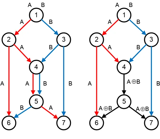
end nodes 6 and 7 to receive both messages, as shown in Figure 2.1(a). The network throughput without network coding is 1/5 message/time unit. However, by sending the bitwise exclusive OR (XOR) of messages A and B in the middle links, two messages can be delivered per time unit to both receivers. As a result, the number of time units can be reduced to 8 and the network throughput is improved to 1/4 message/time unit, i.e., with a 25% improvement.
Following the seminal work of [12], Li et al. [54] showed that a linear coding mechanism is sufficient for the achievement of the multi-cast capacity. The pro-posed linear network coding (LNC) refers to the linear combination at a relay, where the output flow at this node is the linear combination of its input flows. The coefficients of the combination are selected from a finite field. Note that the operation is computed in a finite field, thus the generated message has the same length as the original message. Sink nodes receive these network coded messages, and collect them in a matrix. The original messages can be recovered by any node as long as the matrix has a full rank.
and/or unknown, the deterministic network coding is difficult to realize. In this case, random linear network coding (RLNC) is an efficient approach to apply network coding to such communication networks [55–57]. The main idea of RLNC is to select the linear coefficients in a finite field F in a random way. Therefore, each node sends out packets obtained as a random linear combination stored in its buffer. One prominent result of [55] is that: if the source information is divided into k original packets, each receiver could recover the whole information form any k received network coded packets with probability 1− 1/|F|. For a sufficiently large finite field, this probability is close to 1. Lun et al. [58] showed that RLNC could approximately achieve the network throughput for both unicast and multi-cast sessions in wireless communication networks.
2.3
Wireless Network Coding
Since its inception in information theory in 2000, network coding has attracted a significant amount of research attention [59]. After the initial theoretical studies in wired networks, the applicability of network coding for wireless networks was soon identified and investigated extensively [60]. However, wireless links have higher error rates than wired links which are more reliable and predictable, and wireless links vary over short time scales [61]. Moreover, a major distinguishing feature of wireless networks with wired networks is their multi-cast nature [62,63]. Transmissions in wired network do not interfere with each other, while interfer-ence is unavoidable in MACs. Traditionally, channel-access schemes [64], such as time division multiple access (TDMA) [65], frequency division multiple access (FDMA) [66, 67], and code division multiple access (CDMA) [68] are applied to avoid interference.
Albeit with totally different characteristics, the multi-cast feature of wireless networks provides an opportunity to apply network coding. When a transmitter broadcasts a message, it is likely that all neighboring receivers within the trans-mission range will receive it. Then, utilizing the idea of network coding, these receivers can then transmit the function of overhearing messages to the next hop.
2.3 Wireless Network Coding 13
wireless networks [15]. To date, prominent applications of WNC include TWRCs [14, 19, 73], multi-hop networks [13], multiple access channels [21], and multi-cast channels [22].
A
R
B
Figure 2.2: A single relay two-way relay channel.
The WNC scheme can be illustrated through a very simple single relay TWRC shown in Figure 2.2. In this network, two users exchange messages over a shared wireless half-duplex channel [74] via one intermediate relay.
A R B
Timeslot 1
A R B
Timeslot 2
A R B
Timeslot 3
A R B
Timeslot 4 SA
SA
SB
SB
Figure 2.3: Traditional straightforward scheme.
Traditionally, interference is avoided by prohibiting the overlapping of signals from usersA and B to relay R at the same time slot. Let SA and SB denote the
messages initiated by userAandB, separately. The straightforward transmission scheme can be illustrated by Figure 2.3. It can be seen from the figure, that a number of four time slots are required to complete message exchange between the two users.
On the other hand, Figure 2.4 shows the network coding in the single relay TWRC. In the first and second time slot, users A and B send their messages SA
A R B
Timeslot 1 SA
A R B
Timeslot 3
SR SR
A R B
Timeslot 2 SB
Figure 2.4: Network Coding.
relay R constructs a network-coded message SR as
SR =SA⊕SB, (2.1)
where ⊕ denotes XOR operation being applied over the entire messages of SA
and SB. In the third time slot, relay R broadcasts SR to both users A and B.
Upon reception, user A can extract SB fromSR as follows
SA⊕SR=SA⊕(SA⊕SB) = SB. (2.2)
A similar operation can be applied at user B to recoverSA. Only three time
slots are required with network coding, representing a 50% network throughput improvement over the traditional straightforward scheme.
2.3.1
Analog Network Coding
In [13], Katti et al. embraced interference into two-way relay channels, and proposed analog network coding. The proposed ANC scheme was performed in signal-level rather than bit-level.
The ANC scheme for the single relay TWRC can be divided into two phases, i.e., multi-access (MA) and broadcast phases, as shown in Figure 2.5.
In the MA phase, both users transmit their modulated signals to relay R
simultaneously. The received signal at the relay is
yR=
p
PAhA,RxA+
p
2.3 Wireless Network Coding 15
A R B
MA phase
A R B
Broadcast phase
A
x xB
R
y
R
y
Figure 2.5: Analog network coding.
where nR is the received noise at relay R,
√
PA and
√
PB are the transmission
powers, and xA and xB are the transmitted signals at user A and B, separately.
hA,R and hB,R are the channel coefficients of link A−R and B−R, separately.
The AF relaying strategy is applied at the relay. Therefore, the relay ampli-fies and forwards the received signal to both users in the broadcast phase. For example, the received signal at user A is
yA=G
p
PRhA,RyR+nA
=GpPR
p
PAhA,RhA,RxA+G
p PR
p
PBhA,RhB,RxB+G
p
PRhA,RnR+nA,
where G is the gain at the relay given by
G=
s
1
PA|hA,R|2+PB|hB,R|2 +σ2
,
where σ2 is the noise variance of the received noise n
R. Since user A has the
knowledge of its own transmitted signal xA, the resulting signals after cancelling
interference can be written as
yA∗=GpPR
p
PBhA,RhB,RxB+G
p
PRhA,RnR+nA. (2.4)
The received SNR for message xB can then be calculated as
γB =
G2P
RPB|hA,R|2|hB,R|2
G2P
R|hA,R|2σ2 +σ2
. (2.5)
2.3.2
Physical-Layer Network Coding
In PNC [14], the received signal is decoded to the modular-2 summation of the transmitted messages. Considering a single relay TWRC with binary symmetric channels (BSCs) [75], the two messages sent from the two users are SA and SB,
which are either 1 or 0. The two modulated signals after binary phase-shift keying (BPSK) modulation are either X = 1(S = 1) or X = −1(S = 0). Similar to ANC, two phases are required for the PNC scheme. During the MA phase, the relay receives a combination of two modulated signals YR. The aim of PNC is to
decode the XOR combination of the two codewords, i.e., SR = SA⊕SB. Table
2.1 shows the PNC mapping [76] process at the relay.
Table 2.1: PNC mapping.
Modulation at users Demodulation and Modulation at the relay
Message Signal Rec. Signal Demodulated Combination Trans. Signal
SA SB XA XB YR SR=SA⊕SB XR
0 0 −1 −1 −2 0 −1
0 1 −1 1 0 1 1
1 0 1 −1 0 1 1
1 1 1 1 2 0 −1
The signal constellation can be expressed as the following Figure 2.6, where
(S
A,S
B)=
(-1,-1)
(-1,1)
(1,-1)
(1,1)
S
R=
-1
-1
-A
1
-B
B
A
Figure 2.6: Signal constellation of the received signal at the relay node.
−γ and γ are two decision boundaries. For AWGN channels, A = B = 1, and
A = ||hA,R|
√
PA +|hB,R|
√
PB| and B = ||hA,R|
√
PA − |hB,R|
√
PB| for fading
channels [77, 78]. In the broadcast phase, relay R broadcasts SR to both user A
2.3 Wireless Network Coding 17
messages.
Channel
Decode
PNC
Mapping
y
RP
SA,SB SA SBFigure 2.7: Channel decoding network coding.
When PNC is applied in channel-coded channels, a critical process at the relay is to transform the superimposed channel-coded packets received from two source nodes, i.e., yR=xA+xB+nR, to the network-coded combination of the
source packets, i.e., SR = SA⊕SB. In the traditional multiple access problem,
the relay decodes SA and SB separately and uses network coding to obtain SR.
However, the only interested network-coded information is SA⊕SBg. In [79],
Zhang et al. proposed a new channel decoding network coding (CDNC) for the procedure of yR → SA⊕SB, as shown in Figure 2.7. The relay first decodes yR
to obtain the probability mass function of SA+SB, denoted by PSA+SB(X) =
Pr (SA+SB =X|yR). Then the relay could obtain the target informationSR =
SA⊕SB through the PNC mapping.
A new channel decoding scheme for CDNC based on repeat accumulate (RA) codes was proposed in [79]. The decoder at relay R provides the design of such a decoder along the following three steps: (1) construct a virtual encoder cor-responding to the decoder; (2) construct the Tanner graph of the virtual code; and (3) design the belief propagation algorithm based on the Tanner graph. Al-though the process was only applied on regular RA codes [80], extensions to other channel codes, such as low-density parity-check (LDPC) codes and Turbo codes, are straightforward. A joint design of PNC with Turbo codes [81] and LDPC codes [17] has been used to improve the error performance for PNC in the single TWRC.
2.3.3
Compute-and-Forward
conjecture was achieved in 1975 [84], and shortly afterwards interest in using bandwidth-efficient modulation codes with new structures, e.g., multi-hcodes [85] and lattice codes [86, 87] began.
An n-dimensional lattice Λ is defined by a set of n basis (column) vectors
{g1,g2, ...,gn} in Rn. The lattice Λ is composed of all integral combinations of
the basis vectors, i.e.,
Λ ={l =G·i, i∈Zn}, (2.6)
where Z = {0,±1,±2, ...}, and the n×n generator matrix G is given by G = [g1 g2 ...gn]. It should be noted that the generator is not unique.
Nested lattices was defined in [88], where a pair of n-dimensional lattice (Λ1,Λ2) is called nested if Λ1 ⊂ Λ2, i.e., there exists corresponding generator
matrices G1 and G2, such that
G2 =G1·J, (2.7)
where J is an n×n integer matrix whose determinant is greater than one. The volumes of the Voronoi region [89] of the two nested lattices satisfy
V2 = det{J} ·V1. (2.8)
Figure 2.8 shows an example of nested hexagonal lattices withJ = 3·I, where
I is the 2 by 2 identity matrix. One key result by Erez and Zamir [90] was that nested lattice codes (combined with lattice decoding) can achieve the capacity of the point-to-point AWGN channel
C = 1
2log (1 + SNR). (2.9)
There is a large body of work on lattice codes and their applications in channel coding [88]. Combined with network coding and lattice codes, the CPF scheme was proposed by Nazer et al. in [91]. The CPF scheme relies on codes with a linear structure, specifically nested lattice codes. The linearity of the codebook ensures that integer combination of codewords are also codewords, as shown in Figure 2.9.
2.3 Wireless Network Coding 19
Figure 2.8: Nested lattice.
w1
w1
w2
X2
X2
h1
h2
Z
y w2
Figure 2.9: A simple example of compute-and-forward.
through the MAC. Assuming that the channel coefficients h1 and h2 are both
equal to 1, the received signal at the relay can then be given by
yR=x1+x2+nR. (2.10)
The relay observes a noisy sum of the transmitted codewords and determines the closest lattice point. After taking a modulo operation with respect to the coarse lattice (Λ2), the receiver can invert the mapping and determine the modulo
equivalent to 1, the two coefficients are also chosen as 1. For fading channels, instead of trying to decode the sum of the codewords, the relay aims to decode an integer combination of the codewords (modulo the coarse lattice)
v = [a1x1+a2x2] mod Λ. (2.11)
This combination is also a codeword due to the linear structure of the nested lattice code. If the integer coefficients are close enough to the channel coefficients, then it seems plausible that the relay can decode the function successfully. In other words, the relay can recover the integer combination of codewords as long as the rate of the nested lattice code is at most the computation rate [92]
RCOMP(h,a) = max
a6=0 log
+
||a||2− P|ah †|2
1 +P||h||2
−1
, (2.12)
where log+(x) , max log(x),0, a = [a1 a2] and h = [h1 h2]. The established
computation rate is proven to have significant improvements than conventional relaying strategies in the MAC.
2.4
Other Recent Work
Subsequent growth in wireless network coding has been explosive. The benefits of combining network coding with broadcasting have been investigated in [93,94]. Since the proposed PNC scheme in [14] requires perfect synchronization of the two users, many previous works [14, 20, 95, 96] found that symbol misalignment will result in appreciable performance penalties. Zhang et al. [14] showed that the BER performance penalties due to symbol offset is 3 dB worse for BPSK modulation, and 6 dB for quadrature phase shift keying (QPSK) modulation. In [97], the authors proposed a practical PNC which removed the synchronization assumption in the original PNC scheme. Most recently, Lu et al. in [98] used a belief propagation algorithm in channel-coded PNC, and reduced the penalties caused by the symbol misalignment in asynchronous PNC.
2.4 Other Recent Work 21
follow-up work by Louie et al. showed that ANC can achieve higher maximum sum-rates than the conventional four time slot transmission scheme in the single relay TWRC.
There has been much interest in applying wireless network coding in vari-ous relay networks. In [99], Wang et al. proposed network coding schemes for cooperative relay networks and user cooperation networks. Relay selection was integrated with network coding in [100, 101] for multi-relay networks. Park et al. [102] proposed a hierarchically modulated network coding scheme for asym-metric two-way relay channels. Similar work with network-coded modulation was carried out in [103]. In [104, 105], Xiaoet al. proposed a new finite-field network coding for the multi-user multi-relay network, which showed better performance than superposition coding in binary field.
Furthermore, You et al. extended the analog network coding from two-hop to multi-hop in [106], which is shown to have significant improvement in network throughput. However, the work in [106] is different from the MH-TRC proposed in this dissertation. The difference will be discussed in the corresponding chapter. Most recently, much researchers have tried to integrate wireless network coding with multi-antenna technology to improve network throughput and/or reduce processing complexity [107–110].
Chapter 3
Wireless Network Coding for
Multi-Hop Two-Way Relay
Channels
3.1
Introduction
Multi-hop two-way relay channels are wireless channels that two users employ to exchange their messages through two or more relays. The traditional straight-forward hop-by-hop transmission scheme suffers long delays, low packet delivery efficiency and spectrum efficiency. Recently, the advent of WNC has offered a new opportunity to improve the network throughput and transmission reliability by exploiting interference in intermediate relays. It has been proven that WNC can double the system capacity in a single relay TWRC [20].
In this chapter, the WNC in the single TWRC is extended to the generalized
exchange pattern, and the optimized scheme with the non-symmetrical exchange pattern.
The WNC scheme for the single relay TWRC has been widely studied [14, 19, 73]. The principle of WNC is a network-coded message working with self information cancelation. In the single relay TWRC, the network-coded message is generated at the only relay node, and the self information cancelation is performed at the two user nodes. However, it should be noted that for the MH-TRC, network-coded messages are generated when the packets from two neighboring nodes collide. Therefore, the self information cancelation can be performed on the relay nodes at each reception, or on user nodes at the end of the transmission. For the proposed MH-WNC in this dissertation, self information cancelation is applied only at the user nodes, which leads to less complexity for the relay node compared to the information cancelation at relay nodes upon each reception. This chapter presents a general transmission strategy of the MH-WNC scheme. The system model and transmission strategy in this chapter provide a platform for the performance analysis discussed in the following chapters.
The contributions in this chapter can be summarized as follows:
1. The transmission scheme of MH-WNC for theL-nodeK-message MH-TRC is generalized, and the transmission pattern and transmission events at each node in different time slots are presented;
2. A simulation platform for analyzing the MH-WNC schemes for different scale MH-TRCs is built, and the generalized transmission pattern is illus-trated with grid charts; and
3. The network throughput and communication delays for different schemes in the generalized MH-TRC are evaluated, and the comparison results are summarized.
3.2
Related Work
3.2 Related Work 25
linear networks, where the self information cancelation is performed on the relay nodes at each reception. In the proposed scheme, each relay stores a copy of the message it sends. It then “adds” the inverse of this stored message to the message it receives from the neighboring nodes in the next time slot to recover the new message being forwarded. The results in [14] showed that PNC can achieve the upper-bound capacity, 0.5 frame/time slot in each direction for bi-directional transmissions between the two end nodes [119]. Their scheme was built on the BSC, however the PNC scheme in noisy and fading channels requires perfect decoding. Moreover, the decoding error propagates throughout the transmission.
The relay-aid network coding (RANC) in multi-hop wireless networks was in-vestigated in [120], and the authors exploited PNC into wireless ad hoc networks. In the proposed scheme, nodes are divided into native nodes and relay nodes, where the native node only transmits its own message and the relay node trans-mits the XOR combination of the received messages and its own message. The simulation results showed that the proposed RANC can significantly improve the network throughput over COPE [15].
Combined with multiple antennas technology, Ono et al. proposed an archi-tecture of multi-input and multi-output (MIMO) mesh network incorporated with network coding in [121, 122]. By introducing multiple antennas into multi-hop networks, co-channel interference cancelation and bi-directional transmission can be realized at the same time. The numerical analysis showed that the proposed architecture can achieve significantly higher channel capacity and reliability than that of conventional schemes for the MH-TRC.
hardware. Moreover, the authors did not generalize a transmission scheme for all scale MH-TRCs and there was no outage performance analysis in the published work.
3.3
System Model
Consider a MH-TRC withLnodes{Nl}Ll=1as illustrated in Figure 3.1. User nodes N1 and NL wish to exchange their messages through intermediate relay nodes
{Nl}Ll=2−1. The message sequences to be transmitted by N1 and NL are noted as
U={uk}Kk=1 andV={vk}Kk=1, respectively. It is assumed that only immediately
neighboring nodes are within the transmission range in this network, and signals received from non-neighboring nodes are negligible due to signal attenuation. All the links between two nodes are assumed to have the same capacity of one message per channel per time unit.
N
2N
1 NLN
3N
4N
L-2N
L-1h2 h3 hL-2
hL-1
h1
User Node
User Node
Relay Nodes
Figure 3.1: TheL-nodeK-message multi-hop two-way relay network.
3.3.1
Message Exchange Pattern
Different from the traditional MH-TRC where only one pair of messages are ex-changed between the two user nodes, the K-pair messages can be exchanged via different patterns, such as {u1, v1, u2, v2, ..., uK, vK} (one message to NL, one
message toN1, and so forth), or{u1, u2, v1, v2, ..., vK−1, vK}(two messages to NL,
two messages to N1, and so forth). In this section, two general types of
trans-mission patterns are considered, i.e., symmetrical and non-symmetrical exchange patterns.
3.3 System Model 27
the name suggests, is the message exchange pattern where message exchange between the two users is symmetrical. That is, the two users exchange their messages one by one at an equal rate.
v
ku
1v
1u
2v
2... ...
u
kFigure 3.2: Symmetrical exchange pattern.
For the traditional straightforward relaying scheme, the two user nodes swap messages every L−1 time slots, i.e., user node NL sends message v1
once it receives message u1 from the other end, and so forth. As can be
observed in Figure 3.2, the message sequence exchanged with this pattern is
{(u1, v1),(u2, v2), ...,(uK, vK)}. The message transmission with this
trans-mission pattern is similar to the situation where two people swap words in a telephone conversion.
• Non-symmetrical exchange pattern: The non-symmetrical message exchange pattern refers to the pattern of the message exchange between the two users that is not symmetrical, i.e., the exchange sequence is{(u1, u2, ..., uK),(v1, v2, ..., vK)}, as shown in Figure 3.3.
That is, user node N1 sends its messages continuously every L−1 time
slots, and user node NL starts sending its messages after receiving all the
K messages from user node N1.
This type of transmission is like the car flow on a highway with traffic control, where only one lane is opened for bi-directional traffic. Therefore, when the number of cars in one direction accumulates to a certain point
v
ku
1u
2u
3... ...
u
kv
1v
2... ...
(similar to the number of messages K in the MH-TRC), all the cars in this direction are released at once, while the cars traveling in the other direction are kept waiting.
3.3.2
Communication Delays
The efficiency of message delivery and delay have been the widely studied re-search topics in multi-hop networks in recent years (see, e.g. [27, 28]). An im-portant factor in the performance measurement of a communication system is communication delays, which are usually caused by the long distance between transmitters and receivers. For example, the communication delay between the probe on Mars and control center on the Earth is approximately 3∼21 minutes.
Similarly, it is assumed that the distances between two neighboring nodes in the MH-TRC are identical to each other, and each transmission between two nodes takes one time unit (disregarding the time between the relay node receiving and transmiting the message). It takes L−1 time units for one message to reach the other end in the L-node MH-TRC. Therefore, the communication delay is
L−1 time unit.
The communication delay can be decreased by reducing the distance between two user nodes or applying advanced communication technologies. However, the focus of this dissertation is to improve the network throughput and communica-tion delays with the network coding technique. As can be observed, the L−1 time unit communication delays between the two user nodes cannot be reduced with neither the routing or scheduling schemes, nor the network coding scheme. Therefore, for the performance analysis in the following sections, this type munication delay is not considered. On the other hand, two types of other com-munication delays will be analyzed for the schemes with and without network coding in the following sections:
• t1, the delay between one user node sending the first outgoing message and
receiveing the first incoming message; and
3.4 Non-Network Coding 29
3.4
Non-Network Coding
The Non-NC scheme, opposite to the network coding scheme, is specified to the transmission scheme that avoids interference. This type of schemes usually uses time division techniques to schedule the transmission at each hop. In the follow-ing sections, two types of Non-NC schemes correspondfollow-ing to different exchange patterns are discussed.
3.4.1
Straightforward Scheme
T1 N1
u1
N2 T2 N3 T3 … TL-2 NL-1 TL-1 NL
T2L-2
N1 N2 T2L-3 N3 T2L-4 … TL+1 NL-1 TL NL
T2L-1
N1 N2 T2L N3 T2L+1 … T3L-4 NL-1 T3L-3 NL
… …
T(2K-2)(L-1)
N1 N2 T(2K-2)(L-1)+1 N3 T(2K-2)(L-1)+2… T(2K-1)(L-1)-1 NL-1 T(2K-1)(L-1) NL
T2K(L-1)
N1 N2 T2K(L-1)-1 N3 T2K(L-1)-2… T(2K-1)(L-1)+2 NL-1 T(2K-1)(L-1)+1 NL
v1
u2
uk
vk
u1
v1
u2
uk
vk
Figure 3.4: The straightforward scheme for the MH-TRC.
In the straightforward scheme, to avoid signal colliding [64], intermediate terminals relay the signal from one hop to the next, as shown in Figure 3.4. For non-regenerative systems, relays may amplify and forward the received signal from the previous node, while these relays decode the signal and re-encode it prior to retransmission in regenerative systems. Under this scheme, it takesL−1 time slots to forward one message fromN1 toNL, and a total ofTSF = 2K(L−1)
time slots are required to complete the message sequence exchange.
be given by
CSF =
2K
2K(L−1) = 1
L−1 (message/time slot). (3.1) For the symmetrical message exchange pattern, users node N1 and NL take
turns to transmit their messages until the end of the exchange process. The number of time slots for message uk to reach NL is L−1, and the number of
time slots for messagevkto reach N1 is alsoL−1. Therefore, the communication
delay between user N1 sending its first message and receiving its first message is t1 = 2(L−1). Similarly, the delay between receiving two messages ist2 = 2(L−1).
3.4.2
Optimized Scheme
For the above straightforward scheme, each user sends its message every L−1 time slots. Thus, each node in the network only works once every L−1 time slots. Consequently, this scheme has low network throughput and channel use rate.
On the other hand, it is noted that each node is only able to receive the signal from its neighboring nodes. For example, as relay node N2 cannot receive
the signal from relay node N4, the idle channels can be utilized for transmission
without causing any interference.
By rescheduling the transmission strategy, an optimized scheme is designed as shown in Figure 3.5. With this scheme, user node N1 transmits a new message
every 3 time slots. For example, when node N4 transmits messageu1 toN5 in the
fourth time slot, node N1 sends u2 toN2 at the same time. Under this scheme,
each node in the MH-TRC forwards the received signal to the next neighboring node every 3 time slots, and the transmissions do not overlap with each other due to the two-hop intervals between them. It can be deduced that the total number of time slots required for this optimized scheme is 2[(L−1) + 3(K−1)], and the network throughput is given by
COP=
K
(L−1) + 3(K−1) (message/time slot). (3.2) When the number of messages K is far larger than the number of nodes L, an upper limit of COP can be obtained as
ˆ
COP= lim
K>>L
K
(L−1) + 3(K−1) = 1
3.5 Wireless Network Coding 31
T1
N1 N2 T2 N3 T3 … TL-2 NL-1 TL-1 NL
T2(L-1)+3(K-1)
N1 N2 T2(L-1)+3(K-1)-1 N3 T2(L-1)+3(K-1)-2… TL-1+3(K-1)+2 NL-1 TL-1+3(K-1)+1 NL
T4
N1 N2 T5 N3 T6 … TL+1 NL-1 TL+2 NL
… …
T3(K-1)+1
N1 N2 T3(K-1)+2 N3 T3(K-1)+3… TL-1+3(K-1)-1 NL-1 TL-1+3(K-1) NL
T2(L-1)+6(K-1)
N1 N2 T2(L-1)+6(K-1)-1 N3 T2(L-1)+6(K-1)-2… TL-1+6(K-1)+1 NL-1 TL-1+6(K-1) NL
T2(L-1)+3(K-1)+3
N1 N2 T2(L-1)+3(K-1)+2 N3 T2(L-1)+3(K-1)+1… TL-1+3(K-1)+5 NL-1 TL-1+3(K-1)+4 NL
… … u1
u2
uk
v1
v2
vk
u1
u2
uk
v1
v2
vk
Figure 3.5: The optimized scheme for the MH-TRC.
In comparison with the straightforward scheme, the optimized scheme signif-icantly improves the network throughput when the number of message is large. However, this optimized scheme cannot work when the symmetrical exchange pattern is required. Under this scheme, one user node does not start sending its messages until it receives all the messages from the counterpart user. Therefore, the communication delays with this optimized scheme are t1 = K(L−1) and t2 = 3. Although the waiting time delay t2 is relatively short compared to the
straightforward scheme, it can be found out that the time delay t1 is extremely
long when the number of messages is large, meaning the user has to wait an extremely long period to receive its first message.
3.5
Wireless Network Coding
the case of evenLcan also be extrapolated from the same procedure presented in this section. Note that only the transmission pattern and the simulation platform for MH-WNC are discussed in this chapter, the MH-WNC corresponding to the non-regenerative and regenerative relaying strategies will be analyzed in the two following chapters.
First, time slots are divided into two types, i.e., the odd and even time slots. In an odd time slot, odd-numbered nodes broadcast signals to their neighboring nodes, while in an even time slot, even-numbered nodes broadcast signals to neighboring nodes. The two user nodes N1 and NL send one message every
two time slots simultaneously, and the message sent by N1 and NL in time slot
j ∈ {1,3, ...,2K−1} are
u(j+1)/2 and v(j+1)/2,
respectively. A total number of 2K −1 time slots are required for the two user nodes to complete sending the message sequences.
N2 N3 NL-2 NL-1
N1 NL
N2 N3 NL-2 NL-1
N1 NL
N4
N4
Time slot j Time slot j+1
……
vi
NC NC NC NC NC
t2j+1
y2j
u(j+1)/2 t3j
y3j+1 y4j yL-2j+1 yL-1j yLj+1 y1j+1
t4j+1 tL-2j tL-1j+1
Figure 3.6: Wireless network coding for theL-nodeK-message MH-TRC.
Similar to the WNC scheme for the single relay TWRC, the relay nodes network-codes the received signal and broadcast the network-coded message to the neighboring nodes in the next transmission time slot, as shown in Figure 3.6. The figure only plots the transmission schedule for two time slots j and
3.5 Wireless Network Coding 33
The received signal at relay node Nl in time slot j can be given by
ylj=hl−1tjl−1+hl+1tjl+1+w
j
l, (3.4)
wheretjl is the transmitted signal by relay nodeNl in time slotj,wjl denotes the
received noise at nodeNl in time slot j. For non-regenerative relaying strategies,
the transmitted signaltjl is simply a scaled version of the received signal from the previous time slot yjl−1, which is illustrated in Chapter 4. For regenerative relay-ing strategies, the transmitted signal tjl is the network-coded codeword decoded from yjl−1 (an XORed message with “standard” PNC, or a linear combination with CPF), which is discussed in Chapter 5.
After time slot L−1, the two user nodes will receive the signal containing the messages from the counterpart user node every two time slots. Knowing its own messages, the user nodes can extract the required messages. The user nodes cancel the own signals in the analog field and decode the required messages in MH-ANC, as will be explained in Chapter 4. On the other hand, the user nodes decode the linear combination of outgoing and incoming messages, and solve the linear eqnarrays for the required messages, as will be explained in Chapter 5.
N2
N1 T1 N3 N4 T1 N5
N2
N1 T2 N3 T2 N4 N5
N2
N1 T3 T3 N3 N4 T3 N5
N2
N1 T4 T4 N3 N4 T4 N5
N2
N1 T5 N3 N4 N5
N2
N1 T6 N3 N4 T6 N5
T3
T4
T5
u1
u2
v1
v2
y12 y41
t22 y32 t42
y45
y43
y34
y52
y32
t24
t26
t44
t46
t33
t35
y41
y61
y45
y65
Figure 3.7: Transmission scheme of MH-WNC for the 5-node 2-message MH-TRC.
Table 3.1: Transmission events of MH-WNC for the 5-node 2-message MH-TRC.
Time slot Node Event Received signal
1 N2 N1
u1
−−→N2 y21=h1u1+w12
N4 N4
v1
←−−N5 y51=h4v1+w15
2 N3 N2
t22 −−→N3
t24
←−−N4 y32=h2t22+h3t24+w32
3 N2 N1
u2
−−→N2
t33
←−−N3 y23=h1u2+h2t33+w32
N4 N3
t33 −−→N4
v2
←−−N5 y43=h3t33+h4v2+w43
4 N1 N1
t42
←−−N2 y14=h2t42+w41
N3 N2
t42 −−→N3
t44
←−−N4 y34=h2t24+h3t44+w34
N5 N4
t4 4
−−→N5 y54=h4t44+w 4 5
5 N2 N2
t53
←−−N3 y25=h2t53+w52
N4 N3
t5 3
−−→N4 y45=h3t53+w 5 4
6 N1 N1
t62
←−−N2 y16=h1t62+w61
N5 N4
t6 4
−−→N5 y56=h4t64+w 6 5
A→x B – nodeA transmits messagextoB,
A←x B – nodeA receives messagexfrom B,
A →x B ←y C – node B receives messages xand y from nodes A and C simultaneously in a
multiple-access phase,
A←x B→x C – nodeB broadcasts messagexto nodesAandC in a broadcast phase.
MH-WNC for a 5-node 2-message MH-TRC is illustrated in Figure 3.7 and Table 3.1.
It should be noted that the transmission events at each node depend on the total number of nodes and messages. For example, the number of time slots required for sending all the K messages is less than the number of hops, i.e., 2K−1< L−1. In other words, the two user nodes have completed sending all their messages before the first message from the other end arrives. In this case, the user nodes remain silent until the first message from the other end arrives in time slotL−1, and the relay nodes remain silent when there are no new messages coming from the neighboring nodes.
3.5 Wireless Network Coding 35
Table 3.2: Transmission events of MH-WNC in theL-nodeK-message MH-TRC
(2K−1< L−1).
Node Set of time slots (Ω) Event in the set of time slotj, j∈Ω
N1 {1,3,5, ...,2K−1} N1
uj+1/2
−−−−→ N2
{2K+ 1,2K+ 3,2K+ 5, ..., L+ 2K−4}
{L−1, L+ 1, ..., L−1 + 2(K−1)} N1
tj2
←−−−−N2
NL {1,3,5, ...,2K−1} NL−1
vj+1/2
←−−−−NL
{2K+ 1,2K+ 3,2K+ 5, ..., L+ 2K−4}
{L−1, L+ 1, ..., L−1 + 2(K−1)} NL−1
tjL−1
−−−−→NL
N2 {1} N1
u1
−−−−→N2
{3,5, ...,2K−1} N1
u(j+1)/2
−−−−→ N2
tj2
←−−−−N3
{2K+ 1,2K+ 3,2K+ 5, ..., L+ 2K−4} N2
tj3
←−−−−N3
{2,4, ..., L+ 2K−5} N1
tj2
←−−−−N2
tj2
−−−−→N3
L−1 + 2(K−1) N1
tj2
←−−−−N2
NL−1 {1} NL−1
v1
←−−−−NL
{3,5, ...,2K−1} NL−2
tjL−2
−−−−→NL−1
v(j+1)/2
←−−−− NL
{2K+ 1,2K+ 3,2K+ 5, ..., L+ 2K−4} NL−2
tjL−2
−−−−→NL−1
{2,4, ..., L+ 2K−5} NL−2
tjL−1
←−−−−NL−1
tjL−1
−−−−→NL
L−1 + 2(K−1) NL−1
tjL−1
−−−−→NL
{Nl}l(L=3−3)/2 {1,2, ..., l−1}
S{
L+ 2K−l, ...,TK}
{l} Nl−1
vjl−1
−−−−→Nl
{l+ 2, l+ 4, ..., L−1 + 2(K−1)−l} Nl−1
tjl−1
−−−−→Nl
tjl+1
←−−−−Nl+1
{l+ 1, l+ 3, ..., L−1 + 2(K−1)−2(l−1)} Nl−1
tjl
←−−−−Nl
tjl
−−−−→Nl+1
L−1 + 2(K−1)−2(l−2) Nl−1
tjl
←−−−−Nl
{Nl}Ll=(−2L+1)/2 {1,2, ..., L−l−2}
S
{2K+l, ...,TK}
{L−1−l} Nl
tjl+1
←−−−−Nl+1
{L−l+ 1, L−l+ 3, ...,2(K−1) +l} Nl−1
tjl−1
−−−−→Nl
tjl+1
←−−−−Nl+1
{L−l, L−l+ 2, ...,2(K−1) +l−1} Nl−1
tj l
←−−−−Nl
tj l
−−−−→Nl+1
2(K−1) +l+ 1 Rl
tjl
−−−−→Nl+1
N(L−1)/2 {1,2, ...,(L−3)/2}
S
{2K+ (L−5)/2, ...,TK}
{(L−1)/2,(L+ 1)/2, ...,2(K−1) + (L−1)/2} N(L−3)/2
tj
(L−3)/2
−−−−→ N(L−1)/2
tj
(L+1)/2
←−−−− N(L+1)/2
{N/2 + 1, N/2 + 3, ...,2(K−1) +N/2−1} N(L−3)/2
tj(L−1)/2
←−−−− N(L−1)/2
tj(L−1)/2
−−−−→ N(L+1)/2
events for the case of 2K−1>L−1 can be similarly extrapolated.
The total number of time slots required for the generalizedL-nodeK-message MH-TRC with MH-WNC is TMH-WNC = L −1 + 2(K − 1), and the network
throughput is
CMH-WNC=
2K
L−1 + 2(K−1) (message/time slot). (3.5)
The upper limit of CMH-WNC when the number of messages K is far larger
than the number of nodes L can be obtained as
ˆ
CMH-WNC = lim
K>>L
2K
L−1 + 2(K −1) = 1 (message/time slot). (3.6)
In comparison with Non-NC, MH-WNC significantly improves the network throughput. That is, L−1 times better than the straightforward scheme and (L−1)/3 times better than the optimized scheme.
The messages of the two user nodes are transmitted simultaneously, and both user nodes receive messages from the counterpart user node at the same time slot. Each message needs L−1 time slot to traverse the entire L−1 hops, so the communication delay between one user node sending out its first message and receiving its first message is t1 = L−1. Moreover, since the message is
transmitted every two time slots, both user nodes will receive a new message from the counterpart user node every two time slots after the first message arrives. The communication delay between receiving two messages is t2 = 2. In comparison
with the Non-NC scheme, the MH-WNC gives significant improvement in both communication delays.
3.6
Simulation Platform
The transmission pattern for WNC in the single relay TWRC is quite straightfor-ward and intuitively understood. It only consists of two phases, i.e., the multiple access and broadcast phases. The transmission of each pair of messages is in-dependent, and the transmission of previous messages does not affect that of subsequent messages.
3.6 Simulation Platform 37
transmission of different messages are overlapped. Therefore, a simulation plat-form is built to show the detailed transmission pattern and transmission events at each node of MH-WNC for different scale MH-TRCs. The established simulation platform can also be used to analyze the performance of MH-WNC in Chapters 4 and 5.
Following the transmission scheme, the transmission scenario for MH-WNC can be extrapolated as follows
• User nodes send their messages every two time slots in odd time slots, until they have finished sending all the K messages. They start to receive messages from their neighboring relay nodes from time slotL−1 every two time slots in even time slots until the end of the entire exchange process. They remain silent in the rest time slots; and
• Relay nodes transmit the forward and backward messages once every two
time slots.
Denote by R, Tand the receiving, sending and silent modes of the