ADJUSTABLE DYNAMIC RANGE FOR PAPR REDUCTION SCHEMES IN LARGE-SCALE MIMO-OFDM SYSTEMS
A Thesis submitted by
Thana Udomsripaiboon, M Eng
For the award of
Doctor of Philosophy
Abstract
In a multi-input-multi-output (MIMO) communication system there is a necessity to limit the power that the output antenna amplifiers can deliver. Their signal is a combination of many independent channels, so the demanded amplitude can peak to many times the average value. The orthogonal frequency division multiplexing (OFDM) system causes high peak signals to occur because many subcarrier components are added by an inverse discrete Fourier transformation process at the base station. This causes out-of-band spectral regrowth. If simple clipping of the input signal is used, there will be in-band distortions in the transmitted signals and the bit error rate will increase substantially.
This work presents a novel technique that reduces the peak-to-average power ratio (PAPR). It is a combination of two main stages, a variable clipping level and an Adaptive Optimizer that takes advantage of the channel state information sent from all users in the cell.
Certification of Thesis
This thesis is entirely the work of Mr. Thana Udomsripaiboon except where otherwise acknowledged. The work is original and has not previously been submitted for any other award, except where acknowledged.
Student and supervisors signatures of endorsement are held at USQ.
Prof., John Billingsley Principal Supervisor
Acknowledgments
First and the foremost, I would like to express my deepest gratitude to my principal supervisor Prof. John Billingsley for his endless commitment to directing the research and invaluable guidance. Without his motivation and guidance, would not have been completed.
I would like to express my sincere thanks to my associate supervisor Dr Andrew Maxwell for his support and encouragement throughout my PhD studies.
I am also thankful to my previous supervisor, Prof. Wei Xiang from JCU, for his instructive discussions and constructive suggestions to my thesis.
I would like to thank the Staff Development Scholarship of the University of Phayao for supporting my study at USQ during these three years. In addition, a special thank to all my friends and colleagues at USQ.
I would like to dedicate this work to ‘Jesus Christ’. I am greatly indebted to him for his unconditional love. Last, but not least, my thanks go to my parents for their great support, love and encouragement.
THANA UDOMSRIPAIBOON University of Southern Queensland
Contents
Abstract i
Acknowledgments iii
Contents iv
List of Figures viii
List of Tables xii
Acronyms & Abbreviations xiii
Chapter 1 Introduction 1
1.1 Background 3
1.2 Motivation and Goals 8
1.3 Innovation and Contribution 9
1.4 Thesis Outline 9
Chapter 2 Background Information 11
2.1 An Overview of MIMO Systems 11
2.2 The MU-MIMO Systems 13
2.3 The Large-Scale MIMO Systems 14
2.4 Orthogonal Frequency Division Multiplexing 16
2.5 Power Amplifier – Nonlinearities 21
2.5.1 RF Amplifier Models 24
2.6 Summary 25
Chapter 3 Peak-to-Average Power Ratio (PAPR) 26
3.1 PAPR in OFDM 26
3.1.1 CCDF of PAPR 29
3.2 Categorization of the PAPR Reductions 30
3.2.1 The Signal Scrambling Techniques 30
3.2.2 The Signal Distortion Techniques 32
3.3 Summary 35
Chapter 4 The Adjustable PAPR Reduction Level Controlled with SER
Feedback 39
4.1 The Range of Adjustable PAPR Level 41
4.2 The Adjustable PAPR Level for Clipping Scheme 42
4.3 The Adjustable PAPR Level for PMP 45
4.3.1 SNR, PAPR, and OBR Performance Trade-Offs 48 4.3.2 The FITRA Algorithm Controlled with SER Feedback 51
vi
Chapter 5 The Adaptive PAPR Optimizer 53
5.1 The Adaptive Filter 53
5.2 The Foundation of the APO 54
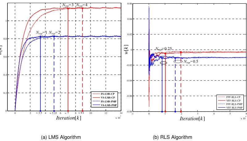
5.3 The Variable Step-size LMS Algorithm 58
5.4 The Variable Forgetting Factor RLS Algorithm 59 5.5 The Overhead by the Signal Repetition of the Algorithms 62
5.6 Summary 65
Chapter 6 System Performance Analysis 67
6.1 The Clipping Noise of the PAPR Reductions 67
6.2 The Adjustable Clipping Level Analysis of the Clipping Scheme 69 6.3 The Adjustable Clipping Level Analysis of the PMP Scheme 75
6.4 SER Performance Analysis 78
6.5 Summary 81
Chapter 7 NumericalResults and Discussion 82
7.1 Out-of-Band Distortion of Each Scheme 85
7.2 The Clipping Scheme with the Least Mean Square Algorithm 86 7.3 The Clipping Scheme with the Recursive Least Squares Algorithm 89 7.4 The PMP Scheme with the Least Mean Square Algorithm 92 7.5 The PMP Scheme with the Recursive Least Squares Algorithm 94
Chapter 8 Conclusions and Future Works 104
8.1 Summary 104
8.2 Conclusions 104
8.3 Future Works 106
References 110
Appendix A 123
A.1 Riemann Sum 123
A.2 Taylor’s Series Expansion 124
A.3 Chebyshev's Inequality 124
A.4 Cauchy-Schwarz Inequality 124
A.5 Jacobian’s Transformation 125
Appendix B Proofs 126
B.1 Discrete Time Independent of Different Clipping Pulses 126
B.2 The Qualified PDF and Moments of γp 128
B.3 The Proof that Both x k[ p]>0 and x k[ p] = 0 or x k[ p]≥
β ζ
( )when ( )β ζ → ∞ 133
B.4 The Proof that Both γpand
τ
p are Uncorrelated when x=0and ( )x≥β ζ 136
Appendix C Floating Point Operations (FLOPs) 137
Appendix D Algorithms 140
viii
List of Figures
1.1 Evolution of wireless standards in the last decade 2
1.2 High dynamic ranges in OFDM symbols 4
1.3 The state of art technology of PAPR reductions 5 1.4 The distorted OFDM signal in time domain and the corresponding impact on
the subcarrier signalling points in the frequency domain 6 1.5 The proposed technique of the adjustable PAPR reductions 7 1.6 An Adaptive PAPR Optimizer retains the transmitted signal before sending 8
1.7 The organization of the thesis 10
2.1 Demand for mobile data traffic and number of connected devices 11
2.2 Point-to-point MIMO system 12
2.3 Multiuser MIMO systems 13
2.4 Block diagram of an OFDM system for nt antennas 17
2.5 The OFDM spectrum 17
2.6 Time/frequency-domain description of OFDM symbols 18 2.7 A mathematical response of a non-linear power amplifier 21
2.9 The spectral regrowth effect in an OFDM spectrum 22 2.10 An in-band/out-of-band distortion creates spectral broadening in an OFDM
bandwidth 23
2.11 The error vector magnitude effect on the 16-QAM constellation 23
3.1 The high peak values of OFDM systems in the time domain 27 3.2 The comparison of the high PAPR in WCDMA, HSUPA, and LTE standards
28 3.3 Categorization of the PAPR reduction schemes 30 3.4 The CCDF performance comparisons for PAPR reduction schemes 36
3.5 The large-scale MIMO-OFDM downlink system 38
4.1 The adjustable PAPR reduction level worked with the Adaptive PAPR
Optimizer 40
4.2 CCDF of transmitted signal after repeated PAPR clipping 40 4.3 The range of adjustable PAPR level for the HPA characteristic 41
4.4 The fixed level of PAPR peak clipping 43
4.5 Adjustable PAPR clipping scheme 44
4.6 The PMP process 46
4.7 CCDF of PMP performance 46
4.8 SNR and PAPR performance trade-offs of PMP with different FITRA
iterations 49
x
5.1 The simple block diagram of an adaptive filter 54 5.2 Operational area of the Adaptive PAPR Optimizer 56 5.3 OFDM-PAPR adjustment over a symbol interval 56 5.4 Relationship between average variable step-size and average SER 59 5.5 Relationship between average variable forgetting factor and average SER 61 5.6 The APO cooperated with the adjustable PAPR reduction level 62
5.7 The convergence process of Adaptive PAPR Optimizers both the
fixed-step-size and the variable step-fixed-step-size 64
5.8 The system model of the large-scale MIMO-OFDM system using the
proposed technique 66
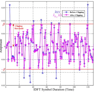
6.1 Transmitted signal x k[ ] with a clipped level threshold 68
6.2 The representation of the exceedance values 69
6.3 An OFDM symbol duration 70
6.4 Frequency spectrum of fpPMP[ ]k 76
7.1 The perfect CSI and the imperfect CSI of the proposed schemes 83 7.2 PSDs of signals transformed by conventional and proposed schemes for
WLAN with 16-QAM 86
7.3 The SER performance of the CP-LMS under the perfect and imperfect CSI 87
7.4 The CCDF (PAPR) performances of the CP-LMS 88
7.5 The SER performance of the CP-RLS under the perfect and imperfect CSI 90
7.7 The SER performance of the PMP-LMS under the perfect and imperfect CSI 92 7.8 The CCDF (PAPR) performances of the PMP-LMS 94 7.9 The SER performance of the PMP-RLS under the perfect and imperfect CSI
95 7.10 The CCDF (PAPR) performances of the PMP-RLS 96
7.11 The SER performance of all proposed techniques under the perfect CSI 98 7.12 The CCDF (PAPR) performances of each scheme with the SER feedback
99 7.13 The unclipped signals, the clipped signals, and the proposed optimizing
signals 99
7.14 The SER performance of the ACL-PMP-VFF-RLS (nt = 10 to 1000) 100
7.15 The SER performance of the ACL-PMP-VFF-RLS (nt = 10 to 1000) 101
7.16 The performance comparisons of the proposed schemes 103
xii
List of Tables
1.1 Conventional base station average power consumption distribution 3
7.1 The total number of the signal repetition of each scheme 84
C.1 The FLOPs counting of each scheme 139
Algorithm 1 The process of the adjustable PAPR level for clipping scheme 140 Algorithm 2 The conventional clipping level for the FITRA algorithm 141 Algorithm 3 The variable clipping level for the FITRA algorithm 141
Algorithm 4 The LMS optimization process 142
Acronyms & Abbreviations
5G Fifth-generation wireless systems ACL Adaptive PAPR clipping level APO Adaptive PAPR Optimizer ASK Amplitude shift keying
BCJR Bahl, Cocke, Jelinek, and Raviv BER Bit error rate
BPSK Binary phase shift keying
BS Base station
CCDF Complementary cumulative distribution function CDF Cumulative distribution function
CP Clipping scheme
CSI Channel state information
dB Decibel
DFE Decision feedback equaliser FFF Fixed-forgetting factor
FS Fixed-step-size
FSK Frequency shift keying HPA High-power amplifier
HSUPA High-speed uplink packet access i.i.d. Independent and identically distributed ICI Intercarrier interference
IDFT Inverse discrete Fourier transformation IIR Infinite impulse response
LMS Least mean square LTE Long term evolution MIMO Multi-input-multi-output
MU Multiuser
OBR Out-of-band ratio
OFDM Orthogonal frequency-division multiplexing PAPR Peak-to-average power ratio
PDF Power density function
PMP Precoding modulation PAPR reduction PSD Power spectral density
QAM Quadrature amplitude modulation QPSK Quadrature phase shift keying RF Radio frequency
RLS Recursive least squares
SSPA Solid state power amplifier VFF Variable forgetting factor
VS Variable step-size
WCDMA Wideband code division multiple access WLAN Wireless local area networks
ZF Zero-forcing
Bold letter: A matrix (e.g. x, X) Bold and italic letter: A vector (e.g. x, X)
⋅ Absolute value operator
⋅ The Euclidean norm
∞
⋅ The infinity norm
( )
*⋅ Conjugate operator
( )
H⋅ Conjugate transpose operator or a Hermitian transposition
( )
†⋅ Pseudo-inversion operator
( )
T⋅ Transpose operator
( )
−1⋅ Inverse operator
[ ]
x x y, Element in row x and column y of xn
I An n × n identity matrix
n m×
n m×
1 An n × m matrix of all ones
( )
diag x Diagonal matrix with the diagonal elements are given
by vector x
[ ]
sign ⋅ The sign function
[ ]
E ⋅ Expectation operator
[ ]
Γ ⋅ Optimization operator
[ ]
Tr x Trace of a matrix x
[ ]
Pr ⋅ The probability function
( )
p ⋅ The power density function
[ ]
⋅F The discrete Fourier transform operator
[ ]
1
− ⋅
F The inverse discrete Fourier transform operator
n m×
An n×m complex valued matrix
*
RX Ex x A covariance of x
*
RX,Y Ex y A cross-covariance of x and y
CN(m, R) Circular symmetric complex Gaussian distribution with
mean m and covariance R
L The Lipschitz constant
⊗ Circular convolution
c
n Number of subcarriers
d
n Number of channel taps
p
n Number of the clipping pulses per an OFDM signal duration
r
n Number of antennas at the user
s
n Length of transmitted data per one packet
t
n Number of antennas at the base station
u
n Number of users
H Channel gain matrix
ZF
G The zero-forcing precoding matrix
ZF
Ω A normalization factor
b
T Time duration of an OFDM block
s
T Time duration of an OFDM symbol
f
∆ Distance between subcarriers in frequency domain q
∆ Length of a quantized step of the adjustable PAPR clipping
θ
∆ Phase change of the frequency component J
∆ Jacobian’s matrix
c
f The cth location of the subcarriers in frequency domain.
λ A signal attenuation factor
PMP
λ A regularization parameter of PMP scheme
( )PMP
( )
CP
β ζ
λ A variable level crossing rate of the adjustable clipping scheme
PMP
Z A number of FITRA iterations
ω The frequency spectrum of the kth discrete-time domain
α
High peak level of PAPR signal of the IDFT signalβ Low peak level of PAPR signal of the IDFT signal
θ
Angle of the IDFT signal[ ]
S
ω
Discrete power spectral density of the IDFT signalζ Average of BER from users
( )
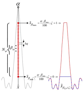
β ζ Adjustable PAPR reduction level
max
β A maximum quantized PAPR level
min
β A minimum quantized PAPR level
qt
β
A percentage of the quantized PAPR level0
/ b
E N Signal to noise ratio
0
γ Signal to noise plus distortion ratio
u
γ Signal to noise plus distortion and interference ratio
ζ
κ
The maximum input dynamic range of the HPAs that have a linear responsemax
xβ The maximum adjustable clipped signal level
min
xβ The minimum adjustable clipped signal level
qt
N Total number of the quantized step
rep
min
J The minimum error of the weight vector w 2
x
σ The variance of x
[ ]
f k
σ The variance of the clipping noise
o
w The optimum weight vector
µ A fixed-step-size of the LMS algorithm
[ ]k
µ
A variable step-size of the LMS algorithmL Length of the Adaptive PAPR Optimizer
χ A fixed-forgetting factor
[ ]k
χ A variable forgetting factor
2
χ An up-crossed process at the variable clipping level
δ
A regularization parameter of the RLS algorithmϖ A ratio of the adjustable clipping level
[ ]
k k A Kalman gain of the RLS algorithm
[ ]k
Θ An inverse correlation matrix of the RLS input signal
[ ]
f k Clipping noise of the PAPR reductions in the discrete-time domain
[ ]
F ω Clipping noise of the PAPR reductions in the frequency spectrum domain
BW The OFDM bandwidth
CP
β The fixed-clipping level of the clipping scheme
PMP
( ) CP
β ζ The adjustable clipping level of the clipping scheme
( ) PMP
β ζ The adjustable clipping level of the PMP scheme τ Total pulse duration of the clipping signal
e
P The probability of the symbol error rate
( )
g
x
A real-valued non-smooth convex function in the FITRA algorithm( )
Chapter 1
Introduction
This thesis addresses the problems that result from high peak-to-average power ratio (PAPR) levels in a multi-antenna communication system by devising a signal shaping method.
Large-scale multi-input-multi-output (MIMO) systems are likely to be adopted as the technology for the fifth-generation wireless systems (5G). Such systems are also called massive MIMO, very large MIMO, hyper-MIMO, or full-dimension MIMO [1-2]. The 5G system must be devised to accommodate the dramatic growth of mobile phones, tablets, laptop computers, smart watches, and other wireless devices. Having many advantages such as high communication reliability, high energy efficiency, and simple signal processing, large-scale MIMO is popular as a topic for research and exploitation [3-8].
In Figure 1.1, orthogonal frequency-division multiplexing (OFDM) together with MIMO has been adopted by present and future wireless local area network (WLAN) standards such as IEEE 802.11a/g, IEEE 802.11n, and IEEE 802.11ac. It is a powerful multi-carrier modulation technique for gaining the bandwidth efficiency of the wireless communication systems. Moreover, one of the main reasons to use OFDM is to increase the robustness to withstand frequency selective fading and narrowband interference. As a result, the advantages of OFDM make this technology a promising alternative for digital broadcasting and communications [9-12].
2
[image:23.595.120.521.173.398.2]Fourier transformation (IDFT) process. High PAPR then causes waveform distortion because of any nonlinear amplifier characteristics, in particular the constrained output power. To resolve this problem, the transmitter would need to employ an expensive amplifier in each transmitting antenna.
Figure 1.1 1
Evolution of wireless standards in the last decade (sourced from [13]).
Nevertheless, a hundred antennas or more may have to be installed with a great number of amplifiers for the next generation of the WLAN. As a consequence, two negative effects will be associated with the multiple antennas of OFDM systems:
1. High power consumption: The greatest power consumption in the OFDM systems is in the power amplifiers as shown in Table 1.1. They typically consume about 80% of the power budget of a base station (BS). Out of concern for the transmitting power, we wish to reduce the output signal to a small proportion of the maximum output power of the amplifiers. A small reduction of an individual transmitted power maps to a huge power reduction when a very large number of antennas are involved. Reducing that power is a key focus of this research. On the other hand, the signal processing’s proportion of the power budget is only around 5% [14].
1
Table 1.1 Conventional BS average power consumption distribution (sourced from [14]).
Appliances Estimated Standard Power (%)
Power Amplifiers 80
Air Conditioning 10
Signal Processing 5
Power Supply 5
2. High cost of the amplifiers in the systems: Even though high values of PAPR have long been a problem in a single antenna of the OFDM transmission, the costs of the amplifiers are increased in proportion to the number of antennas in massive antenna systems. The use of expensive RF amplifier components is an undesirable way to solve this problem in the future [15-16].
In consequence, many researchers have presented a variety of digital processing methods for reducing PAPR, both to tackle the high power consumption and the high price of the amplifiers of a large number of antenna systems [17-18].
1.1 Background
PAPR problems resulting from OFDM have long been known. Although there are remedies for single antenna systems, they become especially serious when an OFDM system is applied in multiple antenna systems. This problem negatively affects the high-power amplifiers (HPAs) at the front end of each antenna.
4
In the past, there have been many efforts to deal with the PAPR problems on a large-scale MIMO-OFDM system, resulting in numerous articles. In [21], the integration between a multiuser (MU) precoding, an OFDM modulation and a PAPR reduction (or a PMP scheme) was presented, where its aim was to reduce the large PAPR. The fast iterative truncation algorithm (FITRA) was devised by Studer et.al. for shrinking the high level of PAPR. In [22], by using a constant envelope precoding, the transmit power and hence the high PAPR of the large antenna of the BS is reduced efficiently. In [23], the weakest eigenchannels are employed for decreasing PAPR. It is utilised with least squares iterative for estimation the high peak level of the transmitted signal. Lastly, in [24], antenna reservation is used for clipped signals to compensate by transmitting correction signals on a set of reserved antennas.
(a) The high peak power of PAPR signal in one subcarrier on OFDM system.
Maximum Input Range of HPA Before Becoming the Nonlinear Region
IDFT
nc 1
Parallel to Serial
2
Time Power
HPA
Maximum Input Range of HPA Before Becoming the Nonlinear Region
(b) The high peak power of PAPR signal in the multiple carriers on OFDM systems.
A method that is frequently used to address large PAPR is a fixed level clipping technique [25, 27]. As shown in Figure 1.3, it is located after the IDFT and before the power amplifiers. This leads to in-band distortion in the form of intermodulation terms and spectral regrowth into the adjacent channel [21-24, 28].
x
1 −
F
β
x
(a) The area of the conventional PAPR reductions in the downlink large-scale MIMO-OFDM system.
x
x
βζ
κ
β
(b) The fixed PAPR reduction’s input/output characteristic.
Figure 1.3 The state of art technology of PAPR reductions.
Figure 1.4 shows in-band distortion by this clipping method. The transmitted signal is assumed to be truncated above 3.5 dB with clip durations t1, t2,… The
values d1, d2,…, d8 are the means of the sums of squared errors of the data sequence
6
system’s own channel, which is called in-band distortion [19, 29]. Therefore, such PAPR reduction schemes will increase the error rate at the receivers.
The present fixed clipping PAPR reduction schemes give no means of adapting the system to a varying condition that is the situations of wireless local area network channels in a cell. This present research is based on devising an optimiser that can adapt the signal shaping to minimise the symbol error rate. This error rate can be determined from the feedback channel that transmits the channel state from the receiver back to the transmitter.
(a)
(b)
Figure 1.4 (a) The distorted OFDM signal in time domain taken from [19]. (b) The corresponding impact on the
subcarrier signalling points in the frequency domain (sourced from [19] and [29]).
tool called the Adaptive PAPR Optimizer (APO) combined with the variable level PAPR clipping technique. Moreover, by the benefit of the channel state information (CSI), it could be adapted itself relating to the network channel by using users’ symbol error rate (SER) feedback [30-33].
The main goal of this project is to reduce the problems of the existing PAPR reductions by equalising the clipped signal before sending to all antennas. By this technique, the equalised signals are compensated by the proposed tool to shape them similar to the unclipped signal as possible. Finally, the area of the proposed method should be located as shown in Figure 1.5, and its expected signal could be shown in Figure 1.6 respectively.
x
1
−
F
α
( )
β ζ
( ) β ζ
x x
optz
(a)The area of the proposed technique on the downlink large-scale MIMO-OFDM system.
ζ
κ
( ) β ζ
opt
z
x
x
(b) The proposed technique’s input/output characteristics.
8
This thesis focuses on decreasing the effects of both in-band and out-of-band distortions from the existing PAPR reduction methods for the large-scale MIMO-OFDM systems, along with a generalised transmission scheme and theoretical studies. The research outcome of this project is able to be further implementation to enhance the wireless network throughput and SER performance of the next generation in wireless communication systems.
100 150 200 250 300
0 0.1 0.2 0.3 0.4 0.5 0.6 0.7 0.8 0.9 1
100 150 200 250 300
0 0.1 0.2 0.3 0.4 0.5 0.6 0.7 0.8 0.9 1
100 150 200 250 300
0 0.1 0.2 0.3 0.4 0.5 0.6 0.7 0.8 0.9 1
(a) The original signal (b) The clipped signal (c) The expected signal Figure 1.6 An APO retains the transmitted signal before sending.
1.2 Motivation and Goals
Even though the negative effects of PAPR on OFDM system and the PAPR reductions are well understood, the literature on the similar analysis for equalising the clipped signal is low. Practically, there is no existing material to optimise the clipped signal for PAPR reduction methods. In doing this, it is necessary to know if any of the PAPR reduction methods available for OFDM could be applied for the proposed technique and if so what are the modifications required. Furthermore, what are the negative impacts of the proposed scheme? How could it be improved by other techniques? These questions need to find answers to achieve the goals to mitigate the PAPR problems of the large-scale MIMO-OFDM systems.
In this project, a study is conducting on the negative effects of PAPR. It also seeks to find the new technique to relieve them. The main goals of this thesis are:
2. To analyse the negative effects of PAPR in the large-scale MIMO-OFDM system;
3. To invent a new method to relieve the PAPR problems;
4. To design an assistant tool for PAPR reduction to equalise the clipped signal; and
5. To propose and analyse the new versions of both a clipping scheme (CP) and a PMP.
1.3 Innovation and Contribution
This thesis provides many innovations and a research project to the PAPR reduction field to improve the SER performance in the large-scale MIMO-OFDM systems. The innovative works of this thesis are:
• Analysis of the negative effects of PAPR in the large-scale MIMO-OFDM systems.
• Analysis of the symbol error rate of the proposed technique.
• Analysis and designing of the new versions of the PAPR reduction schemes. • Designing a new tool to equalise the clipped signal from PAPR reductions. • Designing some algorithms that can adapt themselves relating to the channel
circumstance of the networks to mitigate the PAPR problems in the large-scale MIMO-OFDM systems.
• Academic publishing a research paper to contribute the proposed techniques in the international conference.
1.4 Thesis Outline
10
reduction schemes. They are modified by the conventional PAPR reductions based on a CP and a PMP technique. A new tool to assist the implementation of the proposed PAPR reductions in Chapter 4 is presented in Chapter 5. Moreover, the derivation of this tool will be examined. In Chapter 6, the proposed techniques will be compared with the existing PAPR reduction techniques by all simulation results. Finally, the conclusions and future works of the research are presented in Chapter 7. Figure 1.7 illustrates the organisation of this thesis.
Chapter 2
Background Information
The main aim of this chapter is to provide an overview of the large-scale MIMO-OFDM systems. Moreover, the negative effects of the nonlinearities of amplification are also presented. The high peak of amplitude in transmitted signals causes ill-behaved power amplifiers in the systems such as in-band/out-of-band distortions, spectral regrowth effect, and adjacent channel interference. Finally, both benefits and drawbacks of the OFDM system are given at the end of this chapter.
An overview of the large-scale MIMO systems will be presented from 2.1 to 2.3 respectively. Then, revision of OFDM systems is presented in section 2.4. Finally, the nonlinearities of amplifiers are represented in section 2.5.
2.1 An Overview of MIMO Systems
0 5 10 15 20 25 30 35
2015 2016 2017 2018 2019 2020
E xa by te s pe r M on th Year 0 2 4 6 8 10 12 14
2015 2016 2017 2018 2019 2020
G lo b a l M o b il e D e vi c e s a n d C o n e c ti o n s (B il li o n s ) Year 7.9 11.6
(a) Global mobile data traffic. (b) Global mobile devices and connections growth.
12
Data traffic has rapidly increased during the last few years, with growing numbers of wireless devices being connecting to mobile networks worldwide. This is one of the primary contributors to global mobile traffic increasing. Figure 2.1 shows the demand for mobile data traffic and the number of mobile devices. The mobile data traffic can be expected to reach to 30.6 exabytes per month by 2020, which is the 5 times increasing over 2016. Moreover, the expected number of mobile devices and connections will be around 11.6 billion by 2020. For these reasons, this demand requires the new technology to support its growth in the future [34-36].
Throughput = Bandwidth(Hz) × Spectral Efficiency(bits/s/Hz) (2.1) As shown in (2.1), new technologies are required to gain the throughput for increasing either bandwidth or spectral efficiency. In this thesis, the technology for increasing the spectral efficiency is exploited. A common way to increase the spectral efficiency is the use of the multiple antennas at the transmission [37].
t
n
n
rFigure 2.2 Point-to-point MIMO system.
2.2 The MU-MIMO Systems
To enhance the wireless communications, the MU-MIMO has been shifted from MIMO to gain the spatial multiplexing among many users, which are concurrently served by the multiple antennas at a BS. Even though each user has a single antenna (nr =1), the spatial multiplexing gain can be achieved by MU-MIMO systems [38]. The important users’ reasons are the limited physical size and cheap price requirements of the mobile devices. Some terminals cannot exploit the multiple antenna technologies, whereas the BS can be supported it. Moreover, the MU-MIMO is able to solve the poorly-behaved channels by using scheduling schemes. Also, the line-of-sight propagation, which causes significant reduction of the performance of MIMO systems, can be solved by MU-MIMO systems. Therefore, MU-MIMO has been becoming a hot research topic nowadays [38-43].
t
n
Figure 2.3 MU-MIMO systems.
The advantages and disadvantages of the MU-MIMO systems can be summarily described as sub-topics as follows:
14
• The CSI’s addition: the BS needs to process the received signals coherently with CSI to achieve a high spatial multiplexing gain. It requires the accurate and timely addition of CSI and has been challenging for all researchers in this issue [32].
• Users’ schedules: the user’s scheduling gains the cost of the system implementation. Due to the limited time and frequency resource, the BS serves many users at the same time. So, some groups of the user are only chosen by BS. This can be challenging, especially the high-demand for data traffic growth scenario [47].
2.3 The Large-Scale MIMO Systems
The large-scale MIMO is a type of MU-MIMO systems, where the number of BS antennas and the number of users are large. The more antennas the BS is installed with, the more degrees of freedom are afforded. Additionally, many terminals can simultaneously communicate with the same frequency resource by different time slots. As a result, a gigantic total throughput can be gotten with the large-scale of antennas and ordinary signal processing methods. On the other hand, it also increases the complexity because of the high signal dimensions. The primary inquiry is to reduce the complexity signal processing and high-cost hardware implementation with the achievement of the huge multiplexing gain on a large scale multiple antenna system. In the large-scale MIMO system, each antenna is expected to install a cheap radio frequency module (e.g., simple processing, a low-power amplifier) [3].
The primary advantages of the large-scale MIMO systems are [5, 48]:
• Gigantic spectral efficiency and high communication reliability: by adding with nt−antenna BS and nu−single antenna users, the communication
system obtains increased spectral efficiency and very high communication reliability.
focusing energy by a BS, where each user is spatially located. Therefore, the radiated power can be increased by an order of magnitude with the large-scale of antenna arrays. Then, all users can obtain high energy efficiency. In the case of the fixed number of terminals, doubling the number of BS antennas, and reducing the transmit power by half, the radiated energy efficiency is doubled, whereas the original the spectral efficiency is still maintained.
• Low complexity of the signal processing: in the large-scale MIMO circumstances over the number of terminals, the favourable propagation is served while the channel vectors between a BS and terminals are nearly orthogonal. Moreover, the negative effects from both inter-user interference and thermal noise can be reduced by simple signal processing (e.g., linear precoding in the downlink, linear decoding in the uplink) under the favourable propagation. For this reason, all simple linear processing methods are optimal.
Another advantage of the large-scale MIMO systems is channel hardening. The off-diagonal terms of the H HH
matrix become dramatically weaker compared to the diagonal terms as the size of the channel gain matrixH
increases. By this reason, the negative effects of the small-scale fading are sharply eliminated. For the large-scale fading, the simple signal processing methods such as system scheduling, power control, etc., are able to solve all problems from the large-scale fading as well.
16
2.3.1 Zero-Forcing Precoding
In this thesis, the downlink transmission of the large-scale MIMO systems is focussed. The simple zero-forcing (ZF) processing is used for precoding the 16-QAM modulated vector, s∈nu×1, as
,
ZF
=G s
x (2.2)
where x∈nt×1is the precoded vector and n nt u
ZF
×
∈
G is the ZF precoding matrix.
The matrix
G
ZF is employed for eliminating inter-user interference. It can be represented as(
)
1† H H ,
ZF ZF ZF
−
=Ω =Ω
G H H HH (2.3)
where 1ΩZFis the normalization factor,
( )
⋅ His a Hermitian transposition, and H† is the pseudo-inversion of H.Vice versa, the ΩZFcan be shown in the term of
G
ZF as,
u
ZF H
ZF ZF
n Tr
=
Ω
G G (2.4)
where Tr
[ ]
⋅ is a trace operator [49].2.4 Orthogonal Frequency Division Multiplexing
OFDM is a kind of the frequency division multiplexing modulation. It is utilised as a digital multi-carrier modulation method. A large number of orthogonal subcarriers,
c
n , are employed to transport the precoded data, x. This precoded data is then
divided into many several parallel streams by using a serial-to-parallel converter to each nc subcarrier. Each subcarrier is
2
orthogonal to each other (or they are totally independent of one anther). Finally, the data stream is converted to frequency
1
The normalization factor is used for averaging the fluctuations in the transmit power.
2
For the case of discrete time, two subcarriers are orthogonal as: c0cos(2 ) cos(2 ) 0, .
c c
n
c= πca / n πcb /n = a≠b
domain by employing an inverse discrete Fourier transform (IDFT). In this stage, each IDFT creates the high peak amplitude of PAPR into the data stream after reverting into a single data stream, x∈nt×1 [11, 15].
1
−
F
1
x
2
x
t
n x
1
x
2
x
t
n x
Figure 2.4 Block diagram of an OFDM system for nt antennas.
1
s
f T
∆ =
1
x
x
2x
3x
c1
f
c
n
x
2
f f3
f
c fnc18
Freq uenc
y
dom ain
1
x
2
x
c
x
c
n
x
1
f
2
f
c
f
c
n
f
1X X2 Xc Xnc
1
S
x
2
S
Figure 2.4 shows the block diagram of the IDFT process that is used for nt
antennas. Also, both Figures 2.5 and 2.6 show the OFDM spectrum in frequency domain relating to the time domain. A block of nc data complex symbols is defined by Xc. Then, the OFDM modulated signal can be represented as
2
2
2
1
( ) , (1 ),
c
c c
n
j f t
c s
n c c
x t X e t T
n
π
=−
=
∑
< ≤ (2.5)where Ts is the duration of one OFDM symbol, the distance between subcarriers in the frequency domain can be symbolised as ∆ =f 1/Ts. Each subcarrier is located as
, (1 ).
c c
s c
f c n
T
= < ≤ (2.6)
To maintain the orthogonality among all OFDM symbols, x t( ) is needed to sample in every ∆ =f Ts/nc. Therefore, 3the sampled signal can be shown as the mathematical expression as
2 2 2 [ ] , c s c c c n kT j f n s c n c
x x kT X e
π
=−
= =
∑
(2.7)
where c= f Tc s, and f1 =0, and then x can be shown as
[ ]
1 2 2 2 , c c c n kc j n c n cx x X e
π
−
=−
= =
∑
F (2.8)
where −1
[ ]
⋅F is an IDFT operator [50].
The main advantages of OFDM system can be listed as [2, 8-11, 51]:
• More efficient assistance in multipath environments: the high-speed serial data will be transmitted by dividing up into many much lower-speed serial data signals. This technique makes the bit or symbol periods longer, therefore multipath time delays have less of an impact. In order to resist the multipath
3
20
effects, the system needs to add more subcarriers over a wider bandwidth. It means that the higher frequencies can be used with fewer multipath effects.
• Low-complexity processing: By the benefits of the advances in a digital signal processing, the low- complexity processing can be used with a simple and efficient implementation.
• Low-complexity at receivers:for the above reason, it can reduce the physical size of the terminals. Furthermore, it can decrease the power consumption on the wireless devices.
• A variety of the modulation techniques: for a given chunk of spectrum space, the many modulation techniques are used for widely varying maximum data rates. Simple digital modulations can be employed on OFDM such as amplitude shift keying (ASK), frequency shift keying (FSK), binary phase shift keying (BPSK), quadrature phase shift keying (QPSK), and quadrature amplitude modulation (QAM).
On the other hand, the disadvantages can also be listed as:
• Doppler shifts: a special form of multicarrier modulation by OFDM systems is more sensitive to Doppler spreads than the single-carrier schemes. They influence the carrier frequency offsets, affecting in intercarrier interference (ICI).
• Synchronisation accuracy: another problem of OFDM is the inaccurate synchronisation. Even though the effective OFDM synchronisation enables the data error rates to be kept to a minimum, error rates are exponentially increased by this problem.
• Noise sensitiveness: OFDM is sensitive to high amplitude impulsive noise because the noise energyspreads among all OFDM subcarriers increasing bit error rate (BER) in the overall systems.
2.5 Power Amplifier - Nonlinearities
The results of this thesis are based on simulation. The introduction and overview of RF amplifiers are given in order to provide an understanding of the important theories. Then, those fundamental theories will be written for the simulation program to study its impact on PAPR problems.
An ideal output signal from amplifiers should take any input signal and proportionally gain the output amplitude. In other words, the output should be scaled by the input accurately. Nevertheless, in practical systems, amplifiers cannot scale output signal as the same characteristics as the input signal perfectly. Due to many negative aspects the amplifiers’ characteristics are unavoidably affected. One of them is the ill-behaved signals of PAPR.
Figure 2.7 illustrates a mathematical response of the amplifiers, while Figure 2.8 (a) shows the negative effect of a non-linear amplification of signals in the time domain, and Figure 2.8 (b) shows the typical response of an ideal amplifier compared with a real amplifier [52].
cos( ) a ωt
x
x
2Distrotion
cos(
)
cos (
)
x
Ω=
A
ω
t
+
B
ω
t
+
1−
F
Figure 2.7 A mathematical response of a non-linear power amplifier.
22
Line ar Re
gion
(b) An amplification response of both linear and non-linear amplifiers taken from [53].
Figure 2.8 An effecting of a non-linear amplifier.
Figure 2.9 The spectral regrowth effect in an OFDM spectrum.
independent of the magnitude of the input gain [53]. Both compression and saturation regions will expand each spectral OFDM signal adding up more frequencies in the output signal. Figure 2.9 shows that all frequency spectrums are plotted from signals in Figure 2.8 (a). This leads both an out-of-band distortion and an in-band distortion in the received signal as shown in Figure 2.10 respectively [54].
Figure 2.10 An in-band/out-of-band distortion creates spectral broadening in an OFDM bandwidth taken from [55].
-4 -3 -2 -1 0 1 2 3 4
-4 -3 -2 -1 0 1 2 3 4
-4 -3 -2 -1 0 1 2 3 4
-4 -3 -2 -1 0 1 2 3 4
(a) The received signals without an in-band distortion. (b) The received signals with an in-band distortion.
Figure 2.11 The error vector magnitude effect on the 16-QAM constellation.
24
To solve these problems, the input signal needs to vary within the linear region by whether to reduce the input power or to require the expensive amplifiers (or the widely linear region amplifiers).
The nonlinearities of the amplifier degrade the transmitted signal in many ways. The most significant drawbacks are as following [56]:
• Additional non-linearity of amplifiers creates interference in the terminals.
• Spectral spreading of the OFDM signals causes adjacent channel interference.
• Both deformation and spreading are occurred in the signal constellation.
2.5.1 RF Amplifier Models
Many RF amplifier models are available in many pieces of literature. They can be mainly grouped into three types: the soft limiter, the solid state power amplifier, and the traveling-wave tube. All of them can be shortly described as follows:
• Soft Limiter [57]. The simplest type of the HPA is the soft limiter amplifier. It has no distortion in the input phase of the signal. It plainly cuts the signal magnitude if the signal surpasses a threshold.
• Solid State Power Amplifier (SSPA) [58]. The most widely used model for the amplifier in wireless communications. Its main drawback is that the distortion in amplitude always occurs, but ithas no distortion in the signal phase.
• Traveling-Wave Tube [59-61] also known as Saleh model. The nonlinear distortion occurs in both amplitude and phase. The traveling-wave tube is wideband amplifiers widely used in satellite communications.
In this thesis, the downlink transmission of the large-scale MIMO systems is focussed. The simple zero-forcing processing is used for precoding the 16-QAM modulated vector to be the transmitted vector, t 1
ZF
n
Ω ∈ ×
x , where 2 1
ZF
E xΩ = .
Then, the received vector, y∈nu×1, is given by ;
+
ZF
H
p Ω
= H
where p is the average SNR, z∈nu×1 is the additive noise vector, and ( )⋅T is a
transpose operator [37].
2.6 Summary
This chapter has provided an introduction to large-scale MIMO-OFDM systems as well as some definitions of the non-linear amplifiers. This non-linearity causes negative impacts for the transmitted signal. They include in-band/out-of-band distortions, spectral regrowth effect, and adjacent channel interference. These significant problems increase the overall error rates in the systems.
Chapter 3
Peak-to-Average Power Ratio (PAPR)
This chapter studies the existing PAPR reduction methods for large-scale MIMO-OFDM systems. The fundamental definitions of PAPR will be presented at the beginning of the chapter. Also, many parameters used for measuring the high amount of PAPR will be presented. Finally, the comparison of some PAPR reductions will be shown in the summary section.
Section 3.1 introduces fundamentals of the PAPR problems in OFDM system. Also, the complementary cumulative distribution function (CCDF) of PAPR will be described in its subsection. Section 3.2, PAPR reductions will be categorized. Some of the existing PAPR reductions are represented in this section. Finally, CCDF measurement is used to compare their reduction performance to be presented in section 3.3.
3.1 PAPR in OFDM
A large number of independent signals modulated onto orthogonal subcarriers are contained in the OFDM signals within bandwidths. In Figure 3.1, many subcarrier components are added by an IDFT operation causing high peak values in the time domain. As a result, OFDM systems are known to have a high amount of PAPR compared to single carrier systems [62-63].
degrades the BER, and out-of-band distortion interfering with neighbouring frequency bands. A high PAPR signal requires the RF amplifiers to have a wide range of linear response and therefore they tend to be expensive. In the downlink transmission, the PAPR problem put a high drain on the transmitted power at the BS. In contrast, therefore the uplink transmission, the efficiency of the amplifier is critical due to the limited battery power in a mobile terminal. This is the main requirement for the next generation of the wireless standard to tackle this problem especially in the multiple antenna OFDM systems [64-65].
u
n
1
c
n
f −
2
f
1
f
3
f f4
c
n
f
+ + +
+ +
+
s
T
( )
x t
a user
a user
28
Figure 3.2 A comparison of the high PAPR in WCDMA, HSUPA, and LTE standards taken from [66].
Figure 3.2 shows the typical PAPR in 1WCDMA, HSUPA and LTE signals: WCDMA is about 3.5 decibels (dB), the HSUPA is around 3.5 dBs, and LTE around 8.5 dBs respectively. Both the WCDMA and HSUPA are employed in the third generation of the wireless communication standard, but for LTE is only a standard that is used in the fourth generation. Looking forward at the trend, the multiple antenna systems using OFDM technology will have a higher value of PAPR [66]. Thus, PAPR reduction still remains one of the hot topic research areas in the next generation of the OFDM systems [14, 21-27].
In both [67] and [68], the PAPR for a continuous-time signal, ( )x t , in one symbol duration, Ts, is defined as:
2
2
max ( )
, 1
( ) s
x t
PAPR t < T .
E x t
= ≤
(3.1)
On the other hand, the effect of the discrete-time nature of PAPR signals can be estimated by oversampling the data sequence x. It can also be shown in Figure 2.4
by a factor c and processing cnc-points IDFT of the data block. Therefore, in this
case, the PAPR is defined as
2
2
max [ ]
, 1, 2, , ,
[ ] c
x k
PAPR k cn
E x k
= =
(3.2)
1 WCDMA, HSUPA, and LTE stand for Wideband Code Division Multiple Access, High-Speed Uplink Packet Access, and
where E
( )
⋅ is the expected value, denotes the average,and c is an oversampling factor.3.1.1 CCDF
of PAPR
One of the most regularly used tools for measuring the efficiency of PAPR reduction methods is the cumulative distribution function (CDF). Usually, the 2CCDF is employed instead of CDF because it measures the probability of the exceeding the reference value denoted as PAPR0.
According to the Central Limit theorem for a multi-carrier signal with a large number of subcarriers, the real and imaginary value of the time domain signals have a mean of zero and a variance of 0.5. Therefore, Rayleigh distribution is given by the amplitude of the multi-carrier signal in a central chi-square distribution with two degrees of freedom. This is obeyed for the power distribution of the system [18]. From (2.5) to (2.8), the CDF of the IDFT signal, x, each tth antenna is given by
( ) 1 x,
F x = −e− (3.3)
where
[ ]
1
2 2
2
.
c
c c
n
kc j
n c n c
x x X e
π −
=−
= =
∑
F
Then, the probability of the PAPR for a non-oversampling data block can be written as
[
]
( )nc(
1 x)
nc.Pr PAPR≤x =F x = −e− (3.4)
Moreover, the CCDF of the PAPR can be presented by
[
]
(
0)
0 1 ( 0) 1 1 .
c c
n
n PAPR
CCDF = Pr PAPR>PAPR = −F PAPR = − −e− (3.5)
2
30
Finally, all mathematical equations of the CCDF from Eq. (3.1) to Eq. (3.5) can be simply represented as in Figure 3.3.
3.2
Categorization of the PAPR Reductions
The studies of the PAPR reduction techniques can be divided into two types:signal scrambling techniques and signal distortion techniques [69]. Both categorizations of PAPR reductions can be represented in Figure 3.3.
Figure 3.3 Categorization of the PAPR reduction schemes adapted from [69].
3.2.1
Signal Scrambling Techniques
Signal scrambling techniques scramble the codes or change the signal phases in order to reduce the high PAPR. The precoding techniques can be employed for signal scrambling. They include constant envelope precoding, selected mapping, partial transmit sequences, interleaving, tone reservation, etc. However, the drawback of these techniques is that they increase the number of carriers required to retain the side information.
• Constant Envelope Precoding. Mohammed and Larsson [22] proposed the constant envelope by coding the chosen phase angles of the transmitted signal. By this technique, it reduces the interference between users, causing the reduction of the in-band distortion andhigh PAPR signals. However, this technique requires an extra 2 dB transmission power per antenna in order to send information to receivers without any distortions. Many researchers have been seeking ways to reduce its power of each antenna in large-scale antenna systems.
• Selected Mapping. Bauml et.al. [70] presented a technique for the PAPR reduction. By generating a whole set of candidate signals, it represents the same information, and then the most favourable signal as regards to minimum PAPR are chosen and transmitted. The chosen candidate signal needs to be sent along with the original information explicitly. A goal is to make the occurrence of the peaks less frequent, but not to eliminate the peaks. Nevertheless, an increase in overhead of transmitted signals is driving many researchers to seek ways to reduce its size.
• Partial Transmit Sequences. Muller and Huber [71] invented a novel technique that combines the partial transmit sequences. It is a flexible and an effective peak power reduction method. The main idea behind this technique is the data block. It is grouped into non-overlapping sub-blocks, and then each sub-block is rotated with a statistically independent rotation factor. The time domain signals with the lowest peak amplitude are generated by a rotation factor, which are sent to the receiver as side information. By this technique, the high peak of PAPR is minimized significantly.
Actually, this technique isbuilt from the select mapping technique. It is also found that the partial transmit sequences are more effective than select mapping in order to reduce PAPR problems. However, the same with the constant envelope precoding method, the reduction of the complexity of this technique is a challenge for future research.
32
interleaving it. Therefore, the signal randomization technique for the reduction of the PAPR was invented. The advantage of this technique is that it is less complex than others with the same achievable performance. However, the future development of this method may aggravate a limitation due to the high order of the interleaved data frames.
• Tone Reservation. This technique was invented by Tellado [73]. The main idea of this technique is the reservation of the small group of the OFDM subcarriers for PAPR reduction. The value of the high peak signals in PAPR depends on the numbers of the reserved subcarriers, which are used for minimizing the PAPR formulated as a convex problem.
3.2.2
Signal Distortion Techniques
Signal distortion techniques have recently been studying to decrease the high peak levels of PAPR. In general, these techniques increase the complexity of the system. The clipping technique is therefore more popular than other signal distortion techniques because it is less complex. More practical solutions include PMP, weakest eigenchannels techniques, antenna reservation, peak windowing, peak cancellation, random phase updating, companding, and so on.
The signal distortion techniques can be summed up by the following subsections:
• Clipping Scheme (CP). The most common tool is used for reducing the high amount of PAPR signal [74]. The high peaks of the amplitude are limited by a threshold. A predefined threshold is set for this technique to clip all high range signals in OFDM system. The aim of this method is to satisfy the constraints of the OFDM spectrum so that the transmitted signal does not interfere with neighbouring frequency bands. However, the in-band distortion cannot be avoided causing the increment of BER. The in-band distortion is small when the clipping threshold is high level because the probability of large peaks is small.
level for the transmission signal. On the other hand, the clipping PAPR reduction causes the in-band distortion. This increases the BER, especially in the large-scale MIMO-OFDM systems.
• The Precoding Modulation PAPR Reduction Scheme (PMP). A powerful tool for PAPR reduction technique was proposed by Studer and Larsson [21]. It combines the functionality of precoding, modulation, and PAPR reduction together. For the PAPR reduction, a FITRA algorithm was invented to iteratively shrink the high dynamic range of the PAPR in the frequency domain.The advantage of PMP technique is to highly reduce the high amount of PAPR signals without greatly diminishing BER performance compared with other schemes. Nevertheless, the FITRA algorithm involves the great complexity base on the cycle of the iterative loop. There is a challenge to reduce its complexity.
• Weakest Eigen-channels Techniques.This technique uses the last eigenchannels of a massive MIMO channel to approximate the peaks exceeding a given target value in the least squares fashion [23]. Subtracted from the original signal in the time domain, then approximate exceedance model is created.
The advantage of this technique is that it is the iterative reducing PAPR level. It is suitable for the flexible systems needed to be adjusted the speed of the processing. However, this method requires a highly accurate estimation. Otherwise, it will degrade the entire system by causing serious BER degradation.
• Antenna Reservation.This technique employs a low complex approach to tackling the PAPR problems. The main idea is to intentionally clip signals sent to a set of reserved antennas. It is used for recompensing by transmitting correction signals on one set of antennas. By reserving 25% of transmitted antennas, the high PAPR signal can be reduced about 4 dB with a 15% complexity overhead [75-76].
34
implement this technique, it would be better to able to adjust those reserved antennas depending on system channel circumstances.
• Peak Windowing. This technique was proposed by Nee and Wild [64]. The main idea of this scheme is to remove high PAPR peaks by multiplying those peaks with peak windowing techniques. They include Gaussian shaped window, cosine, Kaiser, and Hamming windows. Compared with the CP, the peak window technique provides better high PAPR removing with better spectral efficiency.
• Peak Cancellation. The peak cancellation method was introduced by May andRohling [77]. This main idea of this technique is to use a time-shifted and scaled reference function by subtracting from the original signal. Then, each subtracted reference function will be used to reduce the high dynamic range of PAPR signals. However, the main focus for many current scientific fields is to find ways to decrease the processing times by adding the correcting function.
• Random Phase Updating. A novel technique that randomizes the phase of transmitting signals by updating algorithm was invented by Nikookar and Lidsheim [78].It can reduce the high PAPR signals of the OFDM signal by assigning a random phase to each subcarrier. This process continuesuntil the high amount of PAPR is reduced bellow the referencing threshold.Both threshold and the number of iterations can be adjusted by BS. The advantage of this method is that it is flexible; BS can adjust some parameters that affect the quality of the BER in the cell. On the other hand, when the number of iterations is increased, the complexity increases substantially. A research challengefor thistechnique is to minimize the complexity from a large iteration.
Many researchers are seeking to reduce the complexity of this method.
sum up, this technique focuses on improving the quantization solution of the low-level of PAPR signals. Due to the low PAPR signals are more likely to occur in transmitted signal than the high PAPR signals.
This thesis focuses on improving the proposed technique on the part of thesignal distortion techniques, which are the CP and the PMP scheme. Their details will be thoroughly explained in Chapter 4 and Chapter 5 respectively.
3.3 Summary
The main goal of this chapter is to review the existing tools that are used for solving the PAPR problems. Several techniques to reduce the PAPR have been invented from many researchers. All of them have the potential to provide a substantial reduction in PAPR. A Comparison of CCDF performance of those techniques will be shown in Figure 3.5. They include CP, PMP, antenna reservation, weakest eigenchannels, constant envelope precoding will be shown in this section. The simulation model of the large-scale MIMO-OFDM downlink system will be used in this comparison with their similar complexity.
In Figure 3.5, the main system parameters are defined as follows: length of transmitted data, ns, 216 bits per 1 user/packet and a number of the packets are 1000
packets, the channel taps nd = 4, the single antenna terminals nu = 10, the number of
the antennas at BS nt = 100, a number of OFDM subcarriers nc = 128. Also, we
utilize 16-QAM constellation to map the coded bits at the BS.
For the channel encoder, a convolution encoder is employed with these parameters: channel code rate = 0.5, code generator polynomials = [1330 1710]
applying with puncturing and random interleaving, constraint length = 7, the Bahl, Cocke, Jelinek, and Raviv (BCJR) decoder is used for channel decoding for each user.
For the parameters for all PAPR reductions, the clipped signal vector xβ for
clipping PAPR scheme is the 80% below the threshold of the original vector x. A
36
PMP
Z = 2000. For the weakest eigenchannels techniques, a weighting factor is 30; the number of iteration is 2. For antenna reservation scheme, a tolerance level of 99% is used as a benchmark for transmitted antennas; the 25% reserved antennas are used for distortion prediction sending [21-23, 74-76, 80].
0 2 4 6 8 10 12 14 16 10-4
10-3 10-2 10-1 100
PAPR[dB]
C
C
D
F
(P
A
P
R
)
Without PAPR reduction Clipping
Antenna Reservation Weak est Eigen-Channels Constant Envelope Precoding PMP
Figure 3.4 The CCDF performance comparisons for PAPR reduction schemes.
In Figure 3.4, it seems that the PMP (a blue squared-line) is the best PAPR reduction scheme, which can highly reduce large PAPR signal about 11dB. On the other hand, the worst case seems to be the clipping PAPR technique (a red triangle line). It only reduces the high dynamic range of PAPR approximately 1.5dB reduction. Finally, other PAPR reduction schemes can be arranged in term of descending order of CCDF, i.e., antenna reservation technique (a pink star line), weakest eigenchannels method (a green diamond line), and constant envelope precoding
![Figure 1.1 1Evolution of wireless standards in the last decade (sourced from [13]).](https://thumb-us.123doks.com/thumbv2/123dok_us/146135.23279/23.595.120.521.173.398/figure-evolution-wireless-standards-decade-sourced.webp)
![Figure 4.6 The PMP process (sourced from [21]).](https://thumb-us.123doks.com/thumbv2/123dok_us/146135.23279/67.595.150.492.235.574/figure-pmp-process-sourced.webp)
![Figure 4.8 SNR and PAPR performance trade-offs of PMP with different FITRA iterations (sourced from [21]).](https://thumb-us.123doks.com/thumbv2/123dok_us/146135.23279/70.595.118.530.69.753/figure-papr-performance-trade-different-fitra-iterations-sourced.webp)
![Figure 4.9 SNR and OBR performance trade-offs of PMP (sourced from [21]).](https://thumb-us.123doks.com/thumbv2/123dok_us/146135.23279/71.595.178.463.72.354/figure-snr-obr-performance-trade-offs-pmp-sourced.webp)

![Figure 5.4 Relationship between average variable step-size and average SER (µ[0]=0, [0]ϕ=1,δ=0.999,ζ[0]=1,ρ=0.001,ξ=0.999,and ϑ =0.00001)](https://thumb-us.123doks.com/thumbv2/123dok_us/146135.23279/80.595.168.457.87.300/figure-relationship-average-variable-step-size-average-ser.webp)