A Dual Modular Multilevel Converter with Shared Capacitor
Sub-Module for MV Open-End Stator Winding Machine Drives
Mohamed S. Diab
*, A. M. Massoud
†, Shehab Ahmed
‡, Barry W. Williams
**Electronic and Electrical Engineering Dept., University of Strathclyde, Glasgow, U.K., †Electrical Engineering Dept., Qatar University, Doha, Qatar,
‡Electrical and Computer Engineering Dept., Texas A&M University at Qatar, Doha, Qatar
Keywords: Medium-voltage variable-speed drives, modular multilevel converter (MMC), open-end stator winding, shared capacitor, submodule (SM) capacitor voltage-ripple.
Abstract
This paper proposes a new dual modular multilevel converter (MMC) topology as a medium-voltage drive for adjustable-speed applications incorporating open-end stator winding machines. A novel concept of sharing one capacitor between each two adjacent-arm sub-modules (SMs) of MMC phase-legs, operating with out-of-phase modulation, is realized through new SM arrangement. This concept allows the MMC to utilize half the number of the SM capacitors, compared to a traditional MMC topology. Additionally, the sizing requirement of the shared capacitor is diminished, which significantly reduces the volume of the drive system and its stored energy. The switching scheme of the shared capacitor between two oppositely modulated SMs eliminates the problem of capacitor wide voltage fluctuations, independent of the operating frequency. Further, the proposed MMC can efficiently operate at near zero frequency, therefore a machine speed-range from zero speed to the rated speed is possible under rated torque operating condition. The proposed MMC topology is elucidated in detail, and its effective performance is verified through simulation.
1 Introduction
With its superior performance in medium- to high-voltage high-power applications, the modular multilevel converter (MMC) has been adopted in industry, serving as a standard converter interface in the high-voltage direct-current (HVDC) transmission systems [1]. The modularity, scalability, redundancy, and reliability are the main features that promoted the MMC for such outstanding industrial position. In addition to the HVDC, the MMC has been presented as a competitor in other applications, such as static synchronous compensators [2] and motor drives [3].
The performance of the MMC in variable-frequency scenarios is not rigid, where its unique operation principles introduce power imbalance between its upper and lower arms. This is eventually manifested in the sub-module (SM) capacitor as a
voltage ripple which inversely depends on both the operating frequency and load current. With the need of driving high-power machines at the medium-voltage (MV) level over a wide speed range, while Volt/Hertz control is applied, the MMC experiences large voltage fluctuations that extremely increase at reduced operating frequencies. This threatens the safety of the MMC switching devices and adversely affects the MMC normal operation. That is why the industrial utilization of the MMC in variable-speed motor drive application is still limited, unless for some quadratic torque loads such as pumps, fans, and compressors [4], [5]. In this context, the MMC has been massively addressed in the literature, for the sake of finding reliable solution that enables the MMC be a commercialized motor drive. Several solutions have been proposed based on both software and hardware approaches to rebalance the energy stored in the SM capacitors at low operating frequencies [6]-[12]. Only few of these solutions successfully resolved the SM capacitor wide voltage fluctuation problem, with detailed verification and results for both stand-still starting and continuous low-frequency operation of high-power machines with multi-megawatt drive systems [10]-[12].
As one alternative candidate, this paper proposes a new MMC topology that applies a novel concept of sharing capacitors between adjacent-arm SMs that operate with out-of-phase modulation. The proposed topology is fundamentally a dual converter configuration, that is, suitable for machines with open-end stator windings. It operates at half the dc-link input voltage, compared to a single-sided MMC topology, for the same output voltage and power level. The topology employs a new SM arrangement that allows its attached capacitor be accessed from two ports, however, in a complementary manner. Although the new SM configuration employs extra switching devices than the common half-bridge (HB) and full-bridge SMs, it achieves outstanding merits as summarized in the following bullets.
Employing half the number of the SM capacitors, compared to conventional MMC topologies. Utilizing a diminished SM capacitance.
Achieving a limited SM capacitor voltage-ripple, independent of the operating frequency.
Figure 1: Circuit diagram of a traditional three-phase dual-MMC-fed open-end stator winding machine.
2 Dual MMC Topology for Open-End Stator
Winding Machines
For high-power applications, machines with open-end stator windings are considered a possible alternative to conventional star- and delta-connected stators, with the advantages of suppressing the switching common-mode (CM) voltages and improving the output voltage quality [13]-[16]. Open-ended machines are fundamentally supplied through dual inverter configurations that employ two inverters, one at each side, which enhances the reliability under fault condition at any one-side. A salient advantage of dual inverter topologies is their ability to generate an output voltage as large as the traditional single-sided ones, however, with a halved dc-link voltage, which reduces the insulation requirement. The dual-inverter topology, feeding open-end stator winding machines, is commonly realized through the two-level voltage source inverter, where different configurations have been adopted in literature to obtain higher number of output voltage levels [17]-[20]. Recently, the dual inverter topology has been realized based on the MMC with a single dc-link voltage, independent of the number of output voltage levels. This eliminates the need of utilizing costly and bulky multi-winding transformers to provide electrically isolated dc sources [10], [21].
Figure 1 shows the circuit diagram of a three-phase dual MMC configuration, where it comprises two MMCs modulated out-of-phase, while each MMC is adopted to feed each end of the machine stator windings. Each MMC is composed of three-phase legs, each formed by two arms connected in series through arm inductors, 𝐿𝑎𝑟𝑚. Each arm consists of N
series-connected SMs, while the SM is commonly an HB cell with a dc capacitor of an equivalent capacitance C and a nominal voltage 𝑉𝑐. Although the dual MMC configuration doubles the
number of employed arm inductors, in comparison to a conventional single-sided MMC topology, the equivalent arm inductance of the dual MMC topology remains unchanged.
The structure of the dual MMC topology can be seen as the direct consequence of dividing each phase-leg of a traditional single-sided MMC into dual complemented legs each employing halved number of SMs, compared to the single-sided phase leg. That is, for the same power level, the total number of employed SMs in a dual MMC topology is the same as the number of employed SMs in a traditional single-sided configuration. In addition, both the voltage and current stress of SM capacitors and switching devices are identical in both MMC configurations.
Referring to Figure 1, the left-side MMC feeds the open-end machine terminals denoted by 𝑎, 𝑏, 𝑐, while the right-side MMC feeds the machine terminals denoted by 𝑎′, 𝑏′, 𝑐′. That
is, the voltage generated across each machine phase is the differential voltage between both machine winding terminals, and is represented as 𝑣𝑗𝑗′, while the current through the
machine winding is 𝑖𝑗, where 𝑗 ∈ {𝑎, 𝑏, 𝑐}, and are calculated
as:
𝑣𝑗𝑗′=𝑉𝑜cos(𝜔𝑡 + 𝜃𝑗) (1a)
𝑖𝑗=𝐼𝑜cos(𝜔𝑡 + 𝜃𝑗− 𝜑) (1b)
where 𝑉𝑜 and 𝐼𝑜 are the amplitudes of the voltage across the
machine windings and their current’s, respectively, 𝜔 is the angular frequency, 𝜃𝑗 is the phase angle of the stator
voltage (𝜃𝑎= 0⁰, 𝜃𝑏 = 120⁰, and 𝜃𝑐= 240⁰), and 𝜑 is the
machine power factor angle. The amplitude of the ac output voltage is defined by both the modulation index 𝑀 and the input voltage 𝑉𝑑𝑐, as shown in (2). It should be noted that the
dc-link voltage utilization is doubled with the dual-converter configurations, compared to their single-sided counterparts.
𝑉𝑜 = 𝑀𝑉𝑑𝑐 (2)
Vdc
a b c
Larm
Larm
arm 1a arm 1b arm 1c
arm 2a arm 2b arm 2c
SM
SM
SM
SM
SM
SM
SM
SM
SM
SM
SM
SM
SM
SM
SM
SM
SM
SM
a b c
three-phase machine
SM
SM
SM
SM
SM
SM
SM
SM
SM
SM
SM
SM
SM
SM
SM
SM
SM
SM
Larm
Larm
arm 1a arm 1b arm 1c
arm 2a arm 2b arm 2c
Vdc
O
iLj
iUj vUj
vLj iLj
iUj
vUj
vLj
1 2
1 2
Vc C
S1
S2 +
-ia
ib
ic
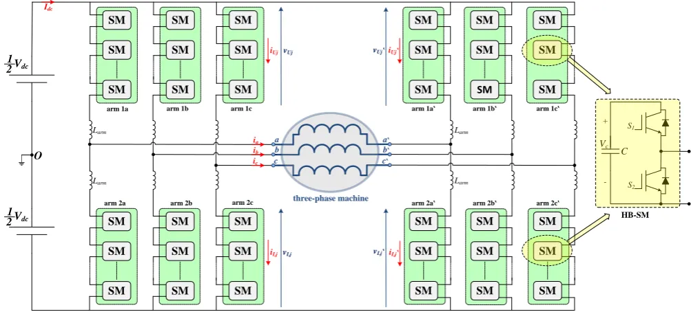
Figure 2: Circuit diagram of the proposed dual MMC configuration with shared-capacitor SM, feeding a three-phase open-end stator winding machine.
Since each two MMC legs with a common machine winding are modulated out-of-phase, the reference voltages for MMC arms, in both converter side, in addition to the arm currents are given by (3) and (4), respectively, where the subscripts U and L are utilized to refer to the corresponding ‘upper’ and ‘lower’ arm.
𝑣𝑈𝑗 = 𝑣𝐿𝑗′=
1 2𝑉𝑑𝑐−
1
2𝑣𝑗𝑗′ (3a)
𝑣𝐿𝑗= 𝑣𝑈𝑗′=
1 2𝑉𝑑𝑐 +
1
2𝑣𝑗𝑗′ (3b)
𝑖𝑈𝑗 = 𝑖𝑐𝑚 𝑗+
1
2𝑖𝑗 (4a)
𝑖𝐿𝑗= 𝑖𝑐𝑚 𝑗−
1
2𝑖𝑗 (4b)
𝑖𝑈𝑗′= 𝑖𝑐𝑚 𝑗′−1
2𝑖𝑗 (4c)
𝑖𝐿𝑗′= 𝑖𝑐𝑚 𝑗′+
1
2𝑖𝑗 (4d)
where 𝑖𝑐𝑚 𝑗 and 𝑖𝑐𝑚 𝑗′ are the CM currents of each two
complemented legs of the dual MMC topology.
3 Proposed Dual MMC Topology
The dual MMC topology infers each machine winding be differentially connected between two MMC legs modulated out-of-phase, as established by (3) and (4). The out-of-phase modulation associated with a common machine winding keeps the stored capacitive energy in one MMC arm to alternate with an opposite phase to the same energy component stored in the adjacent arm of the complemented leg. In other words, the amount of the released capacitive energy in one SM is the same as that absorbed by the oppositely modulated adjacent-arm SM. In [10] and [11], the adjacent-arm SMs are linked together through a power channel that counter-balances the energy variations at the SM level. That is, a dual half-bridge module is adopted between oppositely modulate SMs to allow for a bidirectional power transfer, resulting in a remarkable reduction in the SM capacitor voltage ripple. Instead, this paper
proposes the dual MMC configuration to combine each two capacitors of adjacent-arm SMs into a shared one, while it merges both SMs into a new combined arrangement with a two-port property. A circuit diagram for the proposed dual MMC topology feeding an open-end stator winding machine is shown in Figure 2. The ideal-switch-based representation of the new combined SM in Figure 2 employs three switches at each side of the shared capacitor (𝑆𝐿1, 𝑆𝐿2, and 𝑆𝐿3 at the left
side, and 𝑆𝑅1, 𝑆𝑅2, and 𝑆𝑅3 at the right side). The function of
these switches is to allow a full access to the shared capacitor from either SM port, however, in a complementary manner. That is, if the capacitor is inserted to a corresponding left-side arm, it should be fully isolated from the adjacent right-side arm, and vice versa. The switching of the shared capacitor between two oppositely modulated phase-arms results in a voltage profile with limited fluctuations, where the shared capacitor is experiencing a charging arm current at one switching cycle while the capacitor is then discharged by the out-of-phase adjacent arm current in the next switching cycle.
The possible switching states of the combined SM that allows insertion/bypass of the shared capacitor to/from either SM side are summarized in Table 1, where 𝑉𝐿 and 𝑉𝑅 are the output
voltages at the left- and right-side of the combined SM, respectively. It is worth noting that both 𝑆𝐿2 and 𝑆𝐿3 should
have the same switching action, which is complemented to the switching state of 𝑆𝐿1. Also, 𝑆𝑅2 and 𝑆𝑅3 have the same
switching state, in a complementary manner to 𝑆𝑅1. A practical
implementation for the combined SM necessitates the ideal switches 𝑆𝐿2, 𝑆𝐿3, 𝑆𝑅2, and 𝑆𝑅3 be controlled bi-directional
switches to allow full isolation between the right- and left-side of the combined SM, at all switching states.
𝑺𝑳𝟏 𝑺𝑳𝟐 𝑺𝑳𝟑 𝑺𝑹𝟏 𝑺𝑹𝟐 𝑺𝑹𝟑 𝑽𝑳 𝑽𝑹
0 1 1 1 0 0 𝑉𝐶 0
[image:3.595.98.288.387.520.2]1 0 0 0 1 1 0 𝑉𝐶
Table 1: Switching states of the combined SM. arm 1a arm 2a SM SM SM SM SM SM SM SM SM SM SM SM arm 1a arm 2a Larm arm 1b arm 2b SM SM SM SM SM SM SM SM SM SM SM SM arm 1b arm 2b arm 1c arm 2c SM SM SM SM SM SM SM SM SM SM SM SM arm 1c arm 2c Vdc Vdc O Larm Larm Larm Larm Larm Larm Larm Larm Larm Larm Larm
new combined SM with shared capacitor SL2 SL1 SL3 SR1 + -Vc SR2 SR3
VL VR
a a b b c c
machine winding aa machine winding bb machine winding cc
1 2 1 2
(a)
[image:4.595.50.287.78.339.2](b)
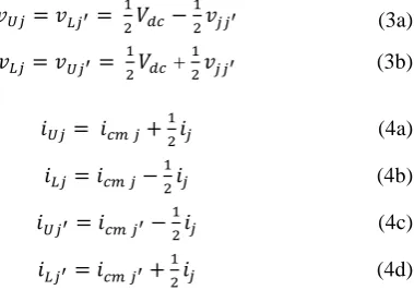
Figure 3: Practical implementation of the shared-capacitor SM using (a) back-to-back series connected IGBTs and (b) single IGBT with full-bridge diodes.
Two configurations for the combined SM can be realized either through two back-to-back series connected IGBTs, as shown in Figure 3a, or by using single IGBT with diode-based full bridge circuit, as shown in Figure 3b. In a comparison, the configuration in Figure 3b has higher conduction loss and lower switching loss than the configuration in Figure 3a. Since the MMC conduction loss is the major contributor to the losses, the SM configuration in Figure 3a is recommended.
4 Control Strategy
Each MMC dual phase-leg is controlled by a modulator that commands a varying number of SMs to be inserted at each time instant according to a phase disposition PWM scheme. Each modulator operates according to a sinusoidal reference input signal which depends on the load current control requirements. Both the upper- and lower-arm currents of only one leg of each dual leg are measured. The voltage balancing of the shared SM capacitors is maintained by a selection mechanism based on capacitor voltage measurements at each switching instance. This mechanism sorts the SM capacitor voltages, and then decides which individual capacitor be inserted to a corresponding right- or left-side arm, according to the arm current direction [22]. It is worth mentioning that the proposed MMC topology employs the same number of current sensors in addition to half the number of voltage sensors, compared to a conventional MMC.
5 Verification
The effectiveness of the proposed dual MMC topology has been verified through simulation, using MATLAB/SIMULINK, with the parameters listed in Table 2.
Number of SMs per arm (N) 5
Input dc voltage (𝑉𝑑𝑐) 12.5 kV
Nominal SM capacitor voltage (𝑉𝑐) 2.5 kV
Rated active power 10 MW
Rated current magnitude (𝐼𝑜) 650 A
Fundamental output frequency (𝑓𝑜) 50 Hz
Carrier frequency of MMC (𝑓𝑐) 2 kHz
Load resistance (R) 15×𝑓𝑜
50 Ω
Load inductance (L) 30 mH
Arm inductance (𝐿𝑎𝑟𝑚) 1 mH
Shared SM capacitance (C) 2 mF
Table 2: Simulation parameters.
The MMC employs 6 phase-legs each with 5 SMs per arm, while supplied from a 12.5 kV dc-link. The MMC is feeding a three-phase RL load with open-end connection. The performance of the MMC is examined at different operating frequencies, where the output voltage is reduced in accordance to the operating frequency reduction, while the load resistance is varied linearly with the operating frequency to maintain the output current constant at the rated value, at all frequencies, to emulate the constant torque characteristic of variable-speed motors. The simulation results are shown in Figure 4 for a steady-state operation of the MMC at 1, 10, and 50 Hz. The differential voltages across the three-phase load terminals are shown to have eleven voltage levels at 50 Hz, while the number of voltage levels decreases with the modulation index reduction at both 10 Hz and 1 Hz. Nonetheless, the quality of the load currents at the three operating frequencies are almost the same, with a current peak equal to the rated value of 650 A. The arm currents are presented for the upper and lower arms of the dual phase-leg 𝑎𝑎′, where it can be shown that both 𝑖
𝑈𝑎 and
𝑖𝑈𝑎′ have a complementary profile, and 𝑖𝐿𝑎 and 𝑖𝐿𝑎′ are also
complemented. The even-order harmonics of the arm currents are almost suppressed at 50 Hz, where the arm inductive reactance is high at such frequency, while they clearly appear in the arm currents recoded at both 1 Hz and 10 Hz since the reactance is lower. The switching of the shared capacitor between two complemented SMs results in a limited capacitor voltage profile, which is almost the same at the three operating frequencies, and exists within ±5%. The CM voltage at the load terminals is bounded to ±2 kV.
6 Conclusion
This paper presented a new dual MMC topology for MV motor drives incorporating open-end stator winding machines. The topology adopts a new concept of merging the capacitors of each two oppositely modulated SMs into a shared one, based on the out-of-phase modulation of each two MMC legs with a common machine winding. The proposed topology reduces the number of employed capacitors, and hence the voltage sensors, by 50% compared to a traditional MMC topology, which reduces the drive system volume and its stored capacitive energy. With the switching of the shared capacitor between two oppositely modulated phase-arms, the capacitor is exposed to a near equal amount of consecutive charging and discharging Vc
+
-SL1
SL2
SL3 SR3
SR2
SR1
SL1 Vc
+
-SR1
SL2 SR2
[image:4.595.331.525.82.228.2](a) (b) (c)
Figure 4: Performance of the proposed dual MMC topology at (a) 1 Hz, (b) 5 Hz, and (c) 50 Hz.
currents. This results in limited voltage fluctuations across the shared capacitor, with a diminished capacitance requirement. The proposed configuration is very suitable for variable-speed drives since it guarantees the continuous operation at any speed/torque condition with the ability of driving multi-megawatt machines from stand still at full-load torque. Since the proposed topology utilizes extra switching devices in the employed SM, an efficiency assessment will be considered in future research.
References
[1] J. Dorn, H. Gambach, J. Strauss, T. Westerweller, and J. Alligan, “Trans bay cable–a breakthrough of vsc multilevel converters in hvdc transmission,” in Cigre Colloquium, 2012. [2] M. Hagiwara and H. Akagi, “Negative-sequence
reactive-power control by a PWM STATCOM based on a modular multilevel cascade converter (MMCC-SDBC),” IEEE Trans. Ind. Appl., vol. 48, no. 2, pp. 720–729, Mar. 2012.
[3] M. Hagiwara, I. Hasegawa, and H. Akagi, “Start-up and low-speed operation of an electric motor driven by a modular
multilevel cascade inverter,” IEEE Trans. Ind. Appl., vol. 49, no. 4, pp. 1556–1565, Jul. 2013.
[4] A. Korn, M. Winkelnkemper, and P. Steimer, “Low output frequency operation of the modular multi-level converter”, in
Proc. IEEE ECCE, 2010, pp. 3993–3997.
[5] S. Debnath, J. Qin and M. Saeedifard, “Control and Stability Analysis of Modular Multilevel Converter Under Low-Frequency Operation,” IEEE Trans. Ind. Electron, vol. 62, no. 9, pp. 5329-5339, Sept. 2015.
[6] A. Antonopoulos, L. Ängquist, H. P. Nee, “Optimal Selection of the Average Capacitor Voltage for Variable-Speed Drives with Modular Multilevel Converters,” IEEE Trans. Power Electron., vol. 30, no. 1, pp. 227-234, Jan. 2015.
[7] B. Tai; C. Gao; X. Liu; Z. Chen, “A Novel Flexible Capacitor Voltage Control Strategy for Variable-Speed Drives with Modular Multilevel Converters,” IEEE Trans. Power Electron., vol. 32, no. 1, pp. 128-141, Jan. 2017.
[8] S. Du; B. Wu; N. Zargari; Z. Cheng, “A Flying-Capacitor Modular Multilevel Converter (FC-MMC) for Medium-Voltage Motor Drive,” IEEE Trans. Power Electron., vol. 32, no. 3, pp. 2081-2089, March 2017.
[9] Z. Kong; X. Huang; Z. Wang; J. Xiong; K. Zhang, "Active Power Decoupling for Submodules of Modular Multilevel Converter," IEEE Trans. Power Electron, vol. PP, no.99, pp.1-1.
[10]M. S. Diab; A. M. Massoud; S. Ahmed; B. W. Williams, "A Dual Modular Multilevel Converter with High-Frequency Magnetic Links Between Sub Modules for MV Open-End Stator Winding Machine Drives," IEEE Trans. Power Electron., vol. 33, no. 6, pp. 5142-5159, June 2018.
[11]M. S. Diab, B. W. Williams, D. Holliday, A. M. Massoud and S. Ahmed, "A modular multilevel converter with isolated energy-balancing modules for MV drives incorporating symmetrical six-phase machines," 2017 IEEE Energy Conversion Congress and Exposition (ECCE), Cincinnati, OH, USA, 2017, pp. 2715-2722.
[12]M. S. Diab; A. M. Massoud; S. Ahmed; B. W. Williams, "A Modular Multilevel Converter with Ripple-Power Decoupling Channels for Three-Phase MV Adjustable-Speed Drives," IEEE Trans. Power Electron., vol. PP, no.99, pp.1-1.
[13]A. Somani, R. Gupta, K. Mohapatra, and N. Mohan, “On the causes of circulating currents in PWM drives with open-end winding ac machines,” IEEE Trans. Ind. Electron., vol. 60, no. 9, pp. 3670-3678, Sep. 2013.
[14]N. Bodo, M. Jones, and E. Levi, “A Space vector PWM with common mode elimination for open-end winding five-phase drives with a single dc supply,” IEEE Trans. Ind. Electron., vol. 61, no. 5, pp. 2197- 2207, May 2014.
[15] P. Rajeevan, K. Sivakumar, K. Gopakumar, C. Patel, and H. Abu-Rub, “A nine-level inverter topology for medium-voltage induction motor drive with open-end stator winding,”
IEEE Trans. Ind. Electron., vol. 60, no. 9, pp. 3627-3636, Sep. 2013.
[16]M. Darijevic, M. Jones, and E. Levi, “An open-end winding four-level five-phase Drive,” IEEE Trans. Ind. Electron., vol. 63, no. 1, pp. 538-549, Jan. 2016.
[17]V. Somasekhar, K. Gopakumar, M. R. Baiju, K. Mohapatra, and L. Umanand, “A multilevel inverter system for an induction motor with open-end windings,” IEEE Trans. Ind. Electron., vol. 52, no. 3, pp. 824– 836, Jun. 2005.
[18]R. S. Kanchan, P. N. Tekwani, and K. Gopakumar, “Three-level inverter scheme with common mode voltage elimination and dc link capacitor voltage balancing for an open-end winding induction motor drive,” IEEE Trans. Power Electron., vol. 21, no. 6, pp. 1676–1683, Nov. 2006. [19]G. Mondal, K. Gopakumar, P. N. Tekwani, and E. Levi, “A
reduced-switch count five-level inverter with common-mode voltage elimination for an open-end winding induction motor drive,” IEEE Trans. Ind. Electron., vol. 54, no. 4, pp. 2344– 2351, Aug. 2007.
[20]P. Rajeevan, K. Sivakumar, K. Gopakumar, C. Patel, and H. Abu-Rub, “A nine-level inverter topology for medium-voltage induction motor drive with open-end stator winding,”
IEEE Trans. Ind. Electron., vol. 60, no. 9, pp. 3627–3636, Sep. 2013.
[21]A. Edpuganti and A. K. Rathore, "Optimal Pulse-Width Modulation for Common-Mode Voltage Elimination Scheme of Medium-Voltage Modular Multilevel Converter-Fed Open-End Stator Winding Induction Motor Drives," IEEE Trans. Ind. Electron., vol. 64, no. 1, pp. 848-856, Jan. 2017.