City, University of London Institutional Repository
Citation:
Sajjad, Ali (2015). A secure and scalable communication framework for inter-cloud services. (Unpublished Post-Doctoral thesis, City University London)This is the accepted version of the paper.
This version of the publication may differ from the final published
version.
Permanent repository link:
http://openaccess.city.ac.uk/14415/Link to published version:
Copyright and reuse: City Research Online aims to make research
outputs of City, University of London available to a wider audience.
Copyright and Moral Rights remain with the author(s) and/or copyright
holders. URLs from City Research Online may be freely distributed and
linked to.
City Research Online: http://openaccess.city.ac.uk/ [email protected]
Framework for Inter-Cloud Services
Ali Sajjad
School of Mathematics, Computer Science & Engineering
City University London
This dissertation is submitted for the degree of
THE FOLLOWING PARTS OF THIS THESIS HAVE BEEN
REDACTED FOR COPYRIGHT REASONS:
p 7: Fig 1.2. International Data Corporation survey.
p 8: Fig 1.3. International Data Corporation survey.
Prof. Muttukrishnan Rajarajan (City University London)
Prof. Andrea Zisman (The Open University)
“For Abbu, Ammi, Ruhma, Zaim and Eesha”
ےس ماگ ہتسجخرضخےل ھچوپ تایح ِزار
ےس مامت ان ِششوک ےہ زیچ کیارہ ہدنز
(ؒلابقا دّمحم ہمالع)
Ask Khidr, him of the blessed feet, for the secret of life
‘Everything that is alive is due to unsuccessful effort’
I would like to express my gratitude to my advisers, Muttukrishnan Rajarajan, Andrea Zisman and Theo Dimitrakos, firstly for agreeing to take me on as a PhD student and then for their continuous guidance in form of fruitful discussions and useful advises. Special thanks to Theo for arranging further funding for me after the third year, without which it would have been very difficult, if not impossible, for me to complete this thesis.
other degree or qualification in this, or any other University. This dissertation is the result of my own work and includes nothing which is the outcome of work done in collaboration, except where
specifically indicated in the text.
Table of Contents vii
List of Figures xiii
List of Tables xix
List of Abbreviations xx
1 Introduction 1
1.1 Overview of Cloud Computing . . . 1
1.2 Characteristics of Cloud Computing . . . 5
1.3 Challenges of Cloud Computing . . . 6
1.4 Research Problem . . . 9
1.5 Research Objectives . . . 12
1.6 Thesis Contributions . . . 15
1.7 Thesis Outline . . . 16
2 Review of Related Work 17 2.1 Client-Server based approaches . . . 22
2.2.1 VNET . . . 24
2.2.2 VIOLIN . . . 26
2.3 Peer-to-Peer based approaches . . . 26
2.3.1 Hamachi . . . 28
2.3.2 N2N . . . 30
2.4 Cloud based approaches . . . 32
2.4.1 Dynamic IP-VPN . . . 33
2.4.2 IPsec VPN . . . 35
2.4.3 Connectivity as a Service (CaaS) . . . 38
2.4.4 Amazon Virtual Private Cloud (Amazon VPC) . . . 41
2.4.5 Google Secure Data Connector . . . 42
2.4.6 CohsiveFT VPN-Cubed . . . 43
2.5 Chapter Summary . . . 45
3 Background 48 3.1 Peer-to-Peer Overlays . . . 50
3.2 Distributed Hash Tables . . . 53
3.3 IPsec . . . 57
3.4 Internet Key Exchange . . . 60
3.5 Key Agreement Protocols . . . 62
3.6 Functional Cryptography . . . 65
3.6.1 Predicate Encryption . . . 68
3.6.2 Identity-based Encryption . . . 69
3.6.3 Attribute-Based Encryption . . . 70
4 Inter-Cloud VPN Overlay 73
4.1 Design and Architecture . . . 75
4.1.1 Inter-Cloud VPN Overlays . . . 77
4.1.2 Secure Virtual Private Connections . . . 83
4.2 Prototype Implementation . . . 88
4.3 Experimental Evaluation . . . 90
4.3.1 Latency Evaluation Methodology . . . 90
4.3.1.1 Measurement Tools . . . 91
4.3.2 Throughput Evaluation Methodology . . . 92
4.3.2.1 Measurement Tools . . . 93
4.3.2.2 Data Size for Throughput Experiments . . . 94
4.3.3 Scalability Evaluation Methodology . . . 99
4.3.3.1 Measurement Tools . . . 99
4.4 Experimental Results and Analysis . . . 102
4.4.1 Service Latency . . . 102
4.4.2 Service Throughput . . . 106
4.4.3 Service Scalability . . . 107
4.5 Chapter Summary . . . 111
5 Inter-Cloud VPN Admission Control 113 5.1 Admission Control in Peer-to-Peer Systems . . . 113
5.1.1 Definition . . . 113
5.1.2 Bootstrapping using Server Lists . . . 114
5.1.3 Bootstrapping using Peer Caches . . . 114
5.1.5 Bootstrapping using Multicast . . . 115
5.2 Threat vectors affecting Inter-Cloud VPN Admission Control . . . . 116
5.2.1 Confidentiality Attacks . . . 117
5.2.2 Integrity Attacks . . . 118
5.2.3 Authentication Attacks . . . 118
5.2.4 Availability Attacks . . . 119
5.3 Security protocol for Inter-Cloud VPN Admission Control . . . 119
5.3.1 The Admission Control Protocol . . . 120
5.3.1.1 Using the Embedded Secret . . . 120
5.3.1.2 Securing the Embedded Secret . . . 121
5.3.1.3 The Complete Protocol . . . 122
5.3.2 Protocol Security Analysis . . . 125
5.3.2.1 Mitigating Confidentiality Attacks . . . 126
5.3.2.2 Mitigating Integrity Attacks . . . 126
5.3.2.3 Mitigating Authentication Attacks . . . 127
5.3.2.4 Mitigating Availability Attacks . . . 127
5.4 Prototype Implementation . . . 128
5.5 Experimental Evaluation . . . 130
5.5.1 Methodology . . . 130
5.5.2 Experimental Results . . . 132
5.5.3 Results Analysis . . . 136
5.6 Chapter Summary . . . 137
6.2 Service based Resource Discovery . . . 141
6.3 Threat vectors affecting Inter-Cloud Resource Discovery . . . 142
6.3.1 Information Confidentiality . . . 143
6.3.2 Traffic Tampering . . . 143
6.3.3 Denial of Service . . . 144
6.3.4 Peer Spoofing . . . 145
6.4 Security protocol design for Inter-Cloud VPN Resource Discovery . 146 6.4.1 Proposed Solution . . . 147
6.4.1.1 Key Policy Attribute based Encryption (KP-ABE) . 148 6.4.1.2 Ciphertext-Policy Attribute based Encryption (CP-ABE) . . . 148
6.4.1.3 Bilinear Pairing . . . 149
6.4.2 Secure Resource Discovery . . . 150
6.4.2.1 System Setup . . . 151
6.4.2.2 Key Generation . . . 152
6.4.2.3 Key Distribution . . . 153
6.4.2.4 Public Key Repository . . . 154
6.4.2.5 Peer Address Resolution . . . 155
6.4.2.6 Neighbour Peer Discovery . . . 155
6.5 Prototype Implementation . . . 156
6.6 Evaluation Methodology . . . 158
6.6.1 Cost of DHT Lookups . . . 159
6.6.2 PKI-based Design for Comparison . . . 159
6.6.3 Experimental Results . . . 160
6.7 Chapter Summary . . . 165
7 Conclusions 167 7.1 Achievements . . . 167
7.2 Challenges and Limitations . . . 171
7.3 Future Work . . . 173
A Virtual Machine Contextualization 175 1 Contextualisation . . . 175
2 Architecture . . . 176
3 Advantages . . . 176
B IPsec Policy 178 C Publications and Patents 180 1 Book Chapter . . . 180
2 Journals . . . 180
3 International Conferences . . . 180
4 Patent . . . 181
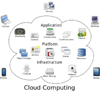
1.1 A logical view of cloud computing, showing examples of the three
basic service models i.e. Infrastructure, Platform and
Application/-Software that can be accessed from a variety of computational
de-vices [161] . . . 4
1.2 A survey showing the answers when 244 IT executives were asked
to rate the importance of a variety of cloud services that benefit
their organizations. This chart shows the percentage of
respon-dents rating each benefit a 4 or 5, on a 1 (not important) to 5 (very
important) scale [70]. . . 6
1.3 A survey showing the answers when 244 IT executives were asked
to rate the top challenges facing adoption of cloud computing in
their organizations in 2008. This chart shows the percentage of
respondents rating each challenge a 4 or 5, on a 1 (not important)
to 5 (very important) scale [70]. . . 8
2.1 Architecture of a VNET based communication framework, showing
the establishment of a secure connection between a client and the
2.2 The architectural design of VIOLIN, showing the three composing
planes i.e., the bottom plane being the actual layer 3 network, the
PlanetLab overlay infrastructure acting as the middle plane, and
the set of VIOLIN entities that are created in the top plane [92]. . . 27
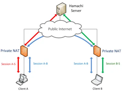
2.3 The Hamachi architecture for linking walled peers. The
fire-wall functionality is usually provided by private NAT devices that
are transparent to the end-users of this service. . . 29
2.4 The N2N overlay network architecture showing the two kinds of
nodes i.e., Super Nodes and Edge Nodes. The figure depicts an
example overlay where two Super Nodes are connected to the
Edge Nodes in a star topology, and the communication between
the Edge Nodes has to pass through the Super Nodes (shown with
dashed lines) [50]. . . 31
2.5 Tunnelling between N2N nodes, with the logical communication
passing through the UDP tunnel in user-space but the physical
sig-nals pass through the tap devices in the kernel-space [50]. . . 32
2.6 Architecture of the Dynamic IP-VPN showing the four dynamic
com-ponents comprising the system and their deployment locations in
an overlay [79]. . . 34
2.7 Architecture of the Full-Mesh IPsecVPN, where each IPsec
gate-way (GW) of a private network (NW) is connected to all the other
gateways [89]. . . 36
2.8 Architecture of the Hub-and-Spoke IPsecVPN, where each IPsec
gateway (GW) of a private network (NW) is connected only to the
2.9 Architecture of the hybrid IPsec-VPN model, where the Hub
gate-way (Hub-GW) is extended using the MOBIKE or Traffic Selector
extension in order to perform load-balancing operations [89]. . . 37
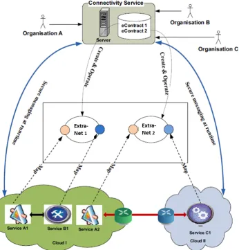
2.10 Architecture of the eContract-based secure intra-cloud and
inter-cloud connectivity service. The figure shows two extranets formed
by the Connectivity Service that offer services from both Cloud I
and Cloud II [40] . . . 39
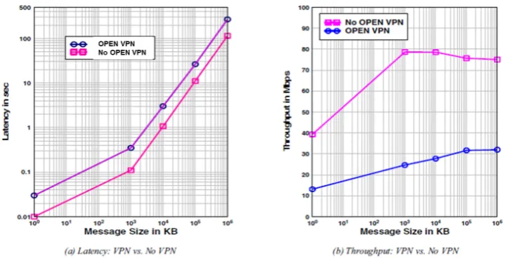
2.11 Performance of the eContract-based secure inter-cloud
connectiv-ity service in terms of effect on latency and throughput. compared
in the presence and absence of OpenVPN tunnels [40]. . . 40
2.12 Architecture of an Amazon VPC deployment. Access to the EC2
instances in Zones A and B is provided through a Virtual Private
Gateway (VPG), which acts as the end-point of the VPN between
the customer gateway and the Amazon cloud [6] . . . 42
2.13 Architectural view of Google Secure Data Connector. The VPN is
established between the Tunnel Servers hosted on Google premises
and the Secure Data Connector hosted on the customer network
[71] . . . 43
2.14 A multi-cloud deployment scenario in VPN-Cubed®. In this
deploy-ment, three VNS3 Manager servers are hosted on three different
cloud regions but only one of them (VNS3 Manager 2) is acting
as the IPsec gateway for the IPsec devices of the customer data
centers [47] . . . 44
3.2 An operational description of a distributed hash table [162] . . . 54
3.3 Architecture of the IPsec and IKE protocols . . . 61
4.1 The two-tiered architecture for the Inter-Cloud VPN, with the nodes
of the Universal Overlay acting as the super peers whereas the
nodes of the VPN overlay acting as normal peers . . . 79
4.2 Sequence diagram depicting the steps undertaken for the
forma-tion of a VPN Overlay, with the VM Contextualizaforma-tion service
boot-strapping the process and the SuperPeer facilitating with secure
enrolment and automatic configuration etc. . . 81
4.3 Architecture of a Inter-Cloud VPN P2P Client node, the architec-ture being identical for both super peer nodes in the Universal
Overlay and VPN peer nodes in a VPN Overlay . . . 83
4.4 Plot of 150 throughput measurements of 1-50 MB data transfers
between ATOS and BT cloud platforms in order to find the most
stable 3-tuple measurements . . . 95
4.5 Plot of 150 throughput measurements of 1-50 MB data transfers
from BT to Flexiant clouds in order to find the most stable 3-tuple measurements . . . 97
4.6 TPlot of 150 throughput measurements of 1-50 MB data transfers
from Flexiant to BT clouds in order to find the most stable 3-tuple measurements . . . 98
4.7 Design of the load scalability experiment to measure the effects of
increasing the numbers of parallel bootstrapping requests from the
4.8 Service latency of 240 HTTP HEAD round-trip time request-response
messagesfromBTtoFlexiant clouds . . . 102 4.9 Service latency of 240 HTTP HEAD round-trip time request-response
messagesfromFlexiantto BT clouds . . . 103 4.10 Service latency of 240 HTTP HEAD round-trip time request-response
messagesfromBTtoATOS clouds . . . 104 4.11 Service latency of 240 HTTP HEAD round-trip time request-response
messagesfromATOSto BT clouds . . . 105 4.12 Throughput of 240 data transmission experimentsfromBTto
Flexi-ant clouds . . . 106
4.13 Throughput of 240 data transmission experimentsfrom Flexiantto
BT clouds . . . 107
4.14 Experiments measuring bootstrapping requests processed per
sec-ond against increasing number of Super Peers . . . 109
4.15 Trend of increasing the number of Super Peers on the average
number of bootstrapping requests processed per second . . . 110
5.1 Duration of the admission control process for 100 trial instances
using the PKI-based and ICVPN methods, on a single cloud
plat-form (BT) . . . 133
5.2 Duration of the admission control process for 100 trial instances
using the PKI-based and ICVPN methods, between BT and
5.3 Duration of the admission control process for 100 trial instances
using the PKI-based and ICVPN methods, between BT and ATOS
cloud platform . . . 135
6.1 No. of fake peers required to intercept all inter-peer communication
in a Kademlia overlay of sizeN . . . 145
6.2 Secure resource discovery for 100 runtime trials between PKI and
Functional Encryption based approaches in ICVPN, on a single
cloud platform . . . 161
6.3 Secure resource discovery for 100 runtime trials between PKI and
Functional Encryption based approaches in ICVPN, between BT
and Flexiant cloud platform . . . 162
6.4 Secure resource discovery for 100 runtime trials between PKI and
Functional Encryption based approaches in ICVPN, between BT
and ATOS cloud platform . . . 163
3.1 Primitives of Functional Encryption . . . 67
4.1 Throughput results with least standard deviation against
correspond-ing transmitted data size . . . 98
5.1 Notations for the Inter-Cloud VPN Admission Control protocol . . . 123
5.2 The Admission Control protocol . . . 125
5.3 Average time taken by the admission control trials . . . 136
3DES Triple Data Encryption Standard
AES Advanced Encryption Standard
AH Authentication Header
API Application Programming Interface
B2B Business-to-Business
BT British Telecom Ltd.
CA Certificate Authority
CaaS Connectivity as a Service
CD-ROM Compact Disc Read-Only Memory
CRM Customer Relationship Management
CSP Cloud Service Provider
DH DiffieHellman Key Exchange
DHT Distributed Hash Table
DoS Denial-of-Service
EC2 Elastic Compute Cloud
ESP Encapsulated Security Payload
FE Functional Encryption
GENI Global Environment for Network Innovations
HTTP HyperText Transfer Protocol
I/O Input/Output
IaaS Infrastructure as a Service
IBE Identity-Based Encryption
ICMP Internet Control Message Protocol
ICV Integrity Check Value
ICVPN Inter-Cloud Virtual Private Network
ID IDentifier
IDC International Data Corporation
IEEE Institute of Electrical and Electronics Engineers
IETF Internet Engineering Task Force
IKEv2 Internet Key Exchange protocol version 2
IP Internet Protocol
IPsec Internet Protocol Security
ISAKMP Internet Security Association and Key Management Protocol
ISO International Organization for Standardization
IT Information Technology
KDC Key Distribution Center
L2TP Layer 2 Tunnelling Protocol
LAN Local Area Network
Mbps Megabits per second
MitM Man-in-the-Middle
MQV Menezes-Qu-Vanstone
NAT Network Address Translation
NIC Network Interface Card
P2P Peer-to-Peer
PaaS Platform as a Service
PBC Pairing-based Cryptography
PID Peer Identifier
PKI Public Key Infrastructure
QEMU Quick EMUlator
REST REpresentational State Transfer
RTT Round-Trip Time
S3 Simple Storage Service
SA Security Associations
SaaS Software as a Service
SADB Security Association Database
SDC Secure Data Connector
SPI Security Parameters Index
SSL Secure Socket Layer
TAP network TAP
TLS Transport Layer Security
TTL Time-To-Live
TTP Trusted Third Party
TUN network TUNnel
UDP User Datagram Protocol
UML User-Mode Linux
URI Universally Resource Identifier
URL Universal Resource Locator
UUID Universally Unique IDentifier
VLAN Virtual Local Area Network
VM Virtual Machine
VMM Virtual Machine Monitor
VNE Virtual Network Edge
VNG Virtual Network Generator
VNM Virtual Network Manager
VNR Virtual Network Router
VPN Virtual Private Network
WAN Wide Area Network
Introduction
1.1
Overview of Cloud Computing
Cloud computing is an extension of the Grid Computing [67] where computing
resources are delivered as a service, typically over the Internet. It follows a
dis-tributed computational model of a large pool of shared, and usually, virtualised
computing resources like storage, processing power, memory, applications,
ser-vices, and network bandwidth. The users of a cloud computing service provider
(CSP) can be provisioned and de-provisioned resources as per their demand in
real-time. Its architecture can be split into two parts, front-end and back-end. The
front-end is a network accessible interface to the users, organizations, and
appli-cations that are using the cloud services. The back-end is typically a large-scale
data centre with a huge pool of storage, computational and network resources.
The cloud service provider gives the end users access to the cloud-based
appli-cations through the front-end interface, which is usually a web interface, either in
Programming Interface (API) calls, to manage and use the back-end resources
they have purchased. The end users are generally oblivious to the tools and
tech-niques being used to provide them with these services (hence the phrase in the
cloud). The main benefits thus achieved are the reduction or elimination of
in-frastructure costs, improved manageability and dynamic adjustment of resources
to meet the changing computation, I/O or networking demands. According to the
National Institute of Standards and Technology (NIST) [115], there are three basic
models associated with cloud
computing:-1. Software as a Service (SaaS)
2. Platform as a Service (PaaS)
3. Infrastructure as a Service (IaaS)
In the SaaS model, software applications are offered to end users through a
web browser or a thin client. These are almost entirely stored and managed in
the cloud and the users do not manage the cloud infrastructure and platform on
which the application is running. This is suitable for applications in the domain of
social networking, collaboration, media and content management etc. Examples
include Customer Relationship Management (CRM) systems like salesforce.com
[136], email services like Gmail [33], Outlook.com [119] etc., online games like
FarmVille [163] etc. and storage services like Wuala [74] and Dropbox [83] etc.
The PaaS model provides a Computing Platform, which is usually a
cus-tomised environment meant to facilitate the design, development and deployment
of applications. it typically includes operating system, programming language,
the responsibility of managing the underlying hardware and software layers off the
application developer and to the cloud service provider. Examples include
Ama-zon Elastic Beanstalk [5], Google App Engine [72] and Windows Azure Compute
[118].
The IaaS model provides creation of virtual hardware resources including
vir-tual machines, virvir-tual networks and virvir-tualized storage. Cloud providers offer
these resources on demand from their large resource pools installed in data
cen-tres across the globe. The users have to install and manage operating systems
on the machines as well as their application software. Examples include services
like Amazon Elastic Compute Cloud(EC2) [7], Amazon Simple Storage Service
(S3) [8], Flexiant [66] and Rackspace Cloud [131].
There are primarily four cloud deployment models, as recommended by the
National Institute of Standards and Technology (NIST):
1. Private Cloud
2. Public Cloud
3. Hybrid Cloud
4. Community Cloud
Private Cloud is a model in which the infrastructure is operated solely for a
single organization. It might be managed internally or by a third-party and also
might be hosted internally or externally. This is used usually to address concerns
related to data security and trust issues.
gen-Figure 1.1: A logical view of cloud computing, showing examples of the three basic service models i.e. Infrastructure, Platform and Application/Software that can be accessed from a variety of computational devices [161]
etc.) or offered on a pay-per-use model (Amazon EC2 etc.).
In the Community Cloud model, the cloud infrastructure is shared by several
organisations with a common policy, security and/or legal considerations. This
helps to reduce costs as compared to a private cloud as it is shared by larger
set of organisations.For example government departments requiring access to
the same information related to infrastructure, such as hospitals, roads, electrical
stations, etc., can utilize a community cloud.
[image:32.595.160.492.110.412.2]or public) to offer the benefits of multiple deployment models. For example, if
the existing private cloud infrastructure is not able to handle the user load, the
cloud can shift workloads between public and private hosting without any service
degradation to the users.
1.2
Characteristics of Cloud Computing
The current buzz around the cloud computing paradigm is due to a number of key
benefits that it provides, which also makes it an interesting research domain in
both academia and the industry [12], [38], [37] . Some of these benefits are
:-• It provides its users with a very low management overhead.
• It gives fast and easy access to a wide range of applications and services.
• It incurs low maintenance cost on its users as a third party is responsible for
the base operations.
• It has the flexibility to scale up and down the resources provided to the users
depending on their real-time requirements.
• Its users have the choice to access their services and applications wherever
they are from a large variety of devices.
• It offers a cost-effective business model as the users pay only for what they
use.
Figure 1.2: A survey showing the answers when 244 IT executives were asked to rate the importance of a variety of cloud services that benefit their organizations. This chart shows the percentage of respondents rating each benefit a 4 or 5, on a 1 (not important) to 5 (very important) scale [70].
their businesses. It is abundantly clear from this figure that there are two key
driving factors for the rapid adoption of cloud computing. The first is its economic
benefits, and the second being the speed, flexibility and ease of use that it offers
to its users for managing and using their IT resources.
1.3
Challenges of Cloud Computing
Most of the currently available IaaS cloud computing solutions are mainly focused
on providing functionalities and services at the infrastructure level, e.g., improved
performance for virtualization of compute, storage and network resources, as well
as necessary fundamental functionality such as virtual machine (VM) migrations
and server consolidation etc. The main reason behind this is that IaaS is the most
IaaS solutions deliver complex systems like development tools, dynamic libraries,
and application life-cycle management suites etc. [69], [147] .
In the cases when higher-level and more abstract concerns need to be
ad-dressed, existing Infrastructure as a Service (IaaS) solutions tend to focus on
functional aspects only. Furthermore, if a cloud’s computational and storage
in-frastructure resources are overloaded due to increased workloads, its services
towards its clients will degrade. The idea of an Inter-Cloud [34] [44] [143] has
been gaining much traction to address such a situation, where a cloud can
bor-row the required infrastructure resources of other clouds. However, in order to
progress from a basic cloud service infrastructure to a more adaptable cloud
ser-vice ecosystem, there is a great need for tools and serser-vices that support and
provide higher-level concerns and non-functional aspects in a comprehensive
manner.
There are three fundamental steps in the life cycle of a service in the cloud
computing ecosystem; the construction of the service, the deployment of the
ser-vice to one or more IaaS clouds and lastly the operational management of the
service. In the resulting scenarios, the presence of the multiple IaaS providers
in the cloud ecosystem is the key issue that needs to be addressed by any
inter-cloud security solution.
A major goal of service owners is to select IaaS providers in an efficient way
in order to host the different components of their services on appropriate clouds.
In this respect, third-party cloud brokers [68] can play a major role in simplifying
the use, performance and delivery of the cloud services. These brokers can also
offer an inter-mediation layer spanning across multiple cloud providers to deliver a
Figure 1.3: A survey showing the answers when 244 IT executives were asked to rate the top challenges facing adoption of cloud computing in their organizations in 2008. This chart shows the percentage of respondents rating each challenge a 4 or 5, on a 1 (not important) to 5 (very important) scale [70].
individual cloud services e.g., aggregation of different services or arbitration for a
best-match service from multiple similar services.
For the numerous interaction possibilities among these parties, whatever the
usage scenarios maybe, the security of data and the communication between the
consumers of the service and its multiple providers is of paramount importance.
This can be demonstrated by the results of a survey done by International Data
Corporation (IDC) [70] in December 2009. As shown in Fig 1.3, the top challenge
1.4
Research Problem
In the light of the above discussion, we advocate that an inter-cloud security
so-lution is highly desirable that would provide a framework enabling seamless and
secure communication between the different actors of a cloud ecosystem over
multiple cloud platforms. Such a solution, however, has to overcome a number
of challenges because of architectural limitations. This is because most of the
current cloud service platforms, and the multi-tenants environments they offer,
make it difficult to give their consumers flexible and scalable control over the core
security aspects of their services like encryption, secure communication and key
management etc. There have been previous attempts to address these security
issues concerning the nature of the problem that we are addressing, but most
of these have been of limited scope. This has been mainly due to the
assump-tions made for the creation of the models of the computation and communication
architectures. We discuss these in much further detail in Chapter 2.
Most of the existing solutions in this domain are based on some variation of a
centralised point-of-control scheme for all of the security concerns of a
commu-nication model, which does not scale well as the entities in that model increase.
This is especially a major concern in a multi-cloud communication paradigm where
the number of virtual machines can increase or decrease dynamically depending
on the application and user work loads. To cater for this particular issue, we need
a secure communication approach that is flexible to adapt to the churn of virtual
machines and also to their deployment locations. This involves having a
decen-tralised control mechanism as well as having an architecture that is tolerant of
join-ing it dynamically. We aim to demonstrate the efficiency of our proposed solution
in this regard by first modelling the dynamics of the communicating entities in
a multi-cloud scenario and then measuring the performance of our solution with
respect to how quickly can it admit the newly joining members into the
communi-cation framework and how resilient it is to members leaving the framework.
Further limitation of most of the existing work is the amount of manual work
needed to set up the solutions they are employing. This is in terms of practical
work needed for the installations, dependency resolutions, configurations and
op-erations etc. The scaling problem comes into play here as well as the number of
entities that need to be managed like this increases. This is also aggravated by
the lack of dynamic network configurability in most cloud providers caused by the
inherent limitations of the fixed network architectures offered by these providers.
Therefore, one of our security engineering objective is to address the requirement
of minimum manual configuration and deployment and focus on a
launch-and-forget type of solution. In order to achieve this objective, we have to ensure the
security and consistency of the entities participating in the communication
frame-work as well. We demonstrate this by constructing this feature as a component
of our architecture that will have the following
properties:-1. Centralised policy-based specification for the operation and security
asso-ciations of the communication framework.
2. Distributed mechanism to carry out the policy’s actions, where each entity
will have the responsibility for its own configuration.
plication, until the next deviation is propagated in the distributed system by
the configuration management component.
Another area of limitation in related literature is comprehensive security
man-agement in general and key manman-agement in particular, as this issue is either
handled in a trivial manner with very little details provided or not discussed at all
in any length. For us the security of the overall solution is of paramount
impor-tance, but it also needs an efficient and scalable design. We achieve this aim by
trying to include the concepts of application partitioning andsecurity by isolation
in our solution. More specifically, we have come up with an intra-application
sand-boxing architecture where we partition our solution into different parts and then
securing each part by using a set of different security schemes. As each part is
logically separated by the other ones and employing different security schemes,
its compromise cannot directly affect the whole solution. The main challenge we
have to address here is how to partition the system into meaningful parts and
which security scheme to then design and apply for each part. We investigate the
partitioning of the solution with respect to the different stages of its life-cycle and
describe the design of the security schemes that we have designed to be applied
at those stages.
Lastly, to determine the efficiency of our solution we have to measure its
per-formance and compare it with similar works. This introduces a major challenge
as direct comparison with most of the related work is almost impossible because
of the issues like vastly different test and simulation environments, architecture
of the solutions and availability of reproducible results from the related work. We
commonly measured and noted when encountering a work of this nature and
then designing suitable experiments. We then demonstrate the results produced
in light of those metrics by running those experiments on multiple commercial
cloud platforms and comparing the performance of our solution with experiments
run in the same environment but without any security enhancements and
fea-tures.
1.5
Research Objectives
We have done an extensive literature review of the secure communication
mech-anisms and frameworks that can be used, either in their current forms or with
modifications, to protect the communication channels between physical or virtual
machines deployed on different cloud platforms. The various limitations, gaps,
and shortcomings of the reviewed works are explored further in Chapter 2. By
analysing these limitations and gaps in the existing work in detail, we have been
able to identify the objectives of our research effort. These objectives will help
with the addressing the shortcomings of the existing works, as well as contribute
towards improvement of the robustness and security of communication
frame-works with-in the scope of the inter-cloud environment. We classify our main
objectives in four categories
:-Objective 1: Distributed inter-cloud communication framework
• To design and develop a communication framework that enables the
ponents of an application deployed in an inter-cloud environment to
• To investigate and design a decentralised command and control mechanism
for its management and operation so that it does not have a single point of
failure.
• To explore and develop an efficient resource discovery mechanism for the
communication framework so that the distributed entities that constitute the
communication framework are able to share and manage the keys they
re-quire for their security operations.
Objective 2: Security
• To design and develop a security mechanism that ensures the integrity and
confidentiality of the network traffic between the components of an
applica-tion utilising our inter-cloud communicaapplica-tion framework.
• To tightly and seamlessly integrate the security mechanism with the
inter-cloud communication framework in such a way that it causes minimum
over-head for the throughput and latency of the communication.
• To design and develop a security protocol for preventing unauthenticated
and unauthorised actors from gaining admission to the communication
frame-work and compare its performance with a standard security protocol.
• To design and develop a security protocol for protecting the resource
discov-ery mechanism used for key management in the communication framework
and compare its performance with a standard security protocol.
• To design and architect the secure communication framework in such a way
that it is able to scale with the increased workload.
• To design and develop an architecture for measuring the load scalability of
the communication framework in terms of operations it is able to perform
when increasing or decreasing the number of the distributed entities.
Objective 4: Ease of Use
• To design and architect the secure communication framework in such a way
that it minimizes the complexity of manual deployment and configuration for
its operation in a multi-cloud environment.
In summary, the overall aim of this research is to address the secure,
flex-ible and scalable communication concerns that in our view must be overcome
in order to provide holistic provisioning of services to consumers from multiple
cloud service providers. We aim to present the architecture and design of an
inter-cloud secure communication framework that offers the features of dynamic
and scalable virtual network formation, efficient and scalable key management
and minimal manual configuration, all on top of secure and private
communi-cation between the components of the service across multiple cloud platforms.
Our architecture provides a virtual network using resources from multiple cloud
providers and offers the capability to transparently run applications on top of this
network while catering for the dynamic growth and shrinkage of the components
1.6
Thesis Contributions
The main contributions of our research effort pertain to the design and
architec-ture of a secure, scalable and robust communication framework for cloud services
and applications running on virtual machines in a multi-cloud environment,
with-out persistent and centralised administration of all the secure connections. Based
on the detailed discussion in the previous and upcoming sections, we have
fo-cused on the following contributions in this
domain:-1. Design and architecture of a scalable inter-cloud secure communication framework that works seamlessly with multiple cloud platforms.
2. A novel and efficient security protocol utilising the zero-knowledge proof
concept for controlling admission into a cloud service’s overlay network.
3. A novel and extremely low-overhead secure resource discovery scheme
util-ising functional encryption for scalable key management.
4. A novel process of using distributed hash tables as a command and control
channel for managing and operating the secure communication framework.
5. Deployment, experimentation and analyses of applications using the secure
communication framework on life commercial cloud platforms for
real-world evaluations.
Furthermore, the research carried out as a part of this effort has resulted in 1
book chapter, 1 international journal publication, 3 international conference
1.7
Thesis Outline
The rest of the thesis is organized as follows: In Chapter 2 we present the
state-of-the-art related works that address issues related to this domain and identify
their gaps and limitations. In Chapter 3 we explain in detail the background of
the technologies, methods and algorithms that we have utilised in the formulation
of our solution. In Chapter 4 we outline the key methodology for our approach
and elaborate on the detailed Inter-Cloud Virtual Private Network (ICVPN)
archi-tecture and design, as well as the experimental set up and the evaluation and
analysis of the performance results of our implementation. In Chapter 5 we
elab-orate on the design of the admission control component of our solution and show
its comparison with other related methods. In Chapter 6 we present the design
and implementation of the secure resource discovery component and compare its
efficiency with existing approaches. We conclude in Chapter 7 with a summary
Review of Related Work
The concept of the Inter-Cloud has come into its own over the recent years as a
logical evolution of the cloud IaaS interoperability. Most of the commercial cloud
service providers designed and offered their services in such a way that the users
could not easily transition to another cloud service provider offering the same
service (this phenomenon is called vendor lock-in). However, due to the costumer
demands for more flexibility and choice, there has been some effort to come up
with solutions that allow the users to use the resources of multiple cloud service
providers to deploy their systems.
Although most of the attention in this area has been given to data storage use
cases, it is also clear to see that parts of customer softwares running on virtual
machines instances on different cloud platforms must be able to dialogue with
each other. One deployed instance of the software must be able to find one or
more other instances for a particular interoperability scenario and be able conduct
transactions or exchange whatever information or data that is required. Thus, an
messaging needs that can support the one-to-one, one-to-many, and
many-to-many communication scenarios.
As of present, there is no such universal inter-cloud communication protocol
and certainly no universal inter-cloud communication security architecture that
ex-ists to address the above problem statement. The aim of our research is to come
up with such a secure communication framework and evaluate it with respect to
different metrics (discussed in detail in later chapters). In order to start this
pro-cess , we identify some of the key security challenges relevant to the inter-cloud
scenario that we will have to
address:-• Preserving the confidentiality and integrity of data in transit to and from a
cloud service instance (typically a virtual machine).
• Unauthorised access to the resources of the communication framework.
• Interception of data in transit (man-in-the-middle attacks).
• Making access to data or keys selectively available to authorised users and
entities.
Most of these challenges have been addressed quite successfully in the
Inter-net scenario by utilising Virtual Private Networks (VPN). Virtual private Inter-networks
have been a mainstay for providing secure remote access over wide-area
net-works to resources in private organizational netnet-works for a long time [120], [106],
[54]. They give the illusion of establishing a connected network by setting up
logi-cal connections between end-points and securing them by using specialized
soft-ware that provides confidentiality and integrity of the traffic flowing between these
the thrust of our research effort is to provision a secure virtual private network
over a multi-cloud infrastructure.
In order to achieve this goal, we have identified a few requirements that help
us in evaluating the related work in relation to the gaps and limitations present in
them that make them unsuitable for an inter-cloud environment. Some of these
requirements have been discussed earlier in section 1.4 in detail. We were able
to establish these requirements as a result of our effort to understand the nature
of our target research environment, i.e., the inter-cloud and the objectives of
in-tended users of this environment, as discussed in existing literature like [34], [44],
and [143].
Additionally, we were also able to gather requirements for our research by
keeping track of the on-going attempts by IEEE (Institute of Electrical and
Elec-tronics Engineers) to create technical standards (IEEE P2302 [88]) for inter-cloud
interoperability. Although the endeavours of IEEE are still in their infancy with
no concrete output thus far, it helped us to discern some useful requirements
from them that were in line with our findings from the study of the related work.
The main insight we were able to ascertain from analysing this material was that
the inter-cloud can not be a single entity, instead it should be a replicated and
hierarchical system. This was based on the observation that the current cloud
computing platforms, that will comprise the inter-cloud environment, are not yet
able to federate and interoperate.
From these sources and more, we were able to identify a few unfulfilled needs
and gaps that must be addressed by anyone who wants to research for a
vi-able inter-cloud communication framework with regards to security, scalability and
into our research requirements and here we summarise the specific requirements
that should be catered for when researching the design and architecture of an
inter-cloud secure communication framework.
• The design of an inter-cloud communication framework should be
decen-tralised, no single-point-of-failure should exist in it.
• The access to the resource of a the communication framework should be
granted only after valid authentication procedures.
– The authentication procedures should be cryptographically strong, e.g.,
user-name/password based methods should be avoided.
– The authentication procedures should be efficient and easy to
auto-mate, e.g., Public Key Infrastructure (PKI) based authentication might
be problematic in this situation due to complex key distribution scheme.
• The communication channels should operate on the lowest layer possible
of the TCP/IP (Transmission Control Protocol / Internet Protocol)networking
model in order to reduce performance overheads.
• The design of an inter-cloud communication framework should be scalable;
the framework should be not burdened as the number of communicating
entities in it increases.
• The management and configuration of the framework should be as simple
and automatic as possible; manual setting up of link and channels should
• The communication framework should be practical in terms of performance,
i.e., it should be secure as that is a fundamental requirement but it should
add as low overheads due to that as possible.
• The design of the framework should be cloud platform independent and not
specific to any particular cloud service provider in order to allow the users
flexibility of choice as well as avoid vendor lock-in.
As mentioned above, the main thrust of our communication framework is the
provisioning of a secure virtual private network in a multi-cloud environment.
Af-ter an elaborate liAf-terature survey process, we were able to classify the existing
virtual private network techniques and solutions into four main categories. First
is the most common type of approach, i.e, those that model their solutions
ac-cording to the client-server model [25]. Second is the category of techniques and
solutions that construct a complete virtual network [81] consisting of virtual
com-putational and network entities as well as customised routing mechanisms. Third
category is composed of techniques that leverage peer-to-peer algorithms and
topologies [133] to construct resilient and fault tolerant virtual private networks.
Fourth and last is the most recent and relevant types of efforts that offer virtual
private networking services on cloud computing platforms [140]. We have picked
a few related works for further elaboration in the following sections. This is not
an exhaustive selection, rather we chose some main candidate recent works to
show-case the approaches they take to solve the problems and the common gaps
2.1
Client-Server based approaches
The discussion of design and architecture of almost all the client-server based
virtual private network solutions can be condensed by just discussing the design
and architecture of OpenVPN [167]. It is the most common and popular VPN
solution (5 million users worldwide as of June 2015 [168]) used to create secure
point-to-point or site-to-site connections for authenticated remote access [116],
[166].
An OpenVPN server runs the central VPN software and each client machine
needs to install a client software so that they can participate in the extended
network. This client application is usually installed and configured by an
admin-istrator and is done on a per-machine basis. OpenVPN uses industry standard
SSL/TLS (Secure Socket Layer and Transport Layer Security) protocols to
pro-vide confidentiality and integrity of the traffic exchanged between its end-points
[87], [27], [104]. It is based on a modular networking model that uses the TAP
(network tap) and TUN (network TUNnel) virtual networking devices as interfaces
between the client and server operating systems. The Universal TAP/TUN driver
[100] is a virtual network interface and its main purpose is to provide IP tunnelling
support to the operating system. Its appears as a network device to all the
appli-cations and users of the operating system and every application that can use a
network interface is able to use this virtual network interface as well. OpenVPN
listens on the TAP/TUN interface for all the network traffic that is being written to it
by the user applications, encrypts it and then sends it to the destination machine,
where another OpenVPN client will be present to receive the data from its
Gaps and Limitations:
However, the main problem in client/server based approaches like OpenVPN
is that they require centralized servers to manage the life cycle of all the secure
connections for the participating clients, hence suffering from a single
point-of-failure. Furthermore, for authentication of the OpenVPN client, a simple
user-name / password based system is used. There is also the possibility of
us-ing a PKI based system for client authentication but that adds the further key
management complexity as well as the overheads associated with PKI-based
ap-proaches. This can be a major drawback as the issue of key distribution among
all the participating clients in a VPN is non-trivial, especially when the software
itself does not provide any key distribution service and all keys have to be
man-ually transferred to individual hosts [105]. In case of PKI model, an additional
requirement of a trusted Certificate Authority exists that has to issue individual
certificates to all the servers and clients constituting a VPN, which incurs an
addi-tional communication overhead when forming a virtual private network. Another
issue is the quite complex and error prone configuration problems especially if you
want to construct and manage a large-scale network not having a relatively simple
topology, as it would require customized configuration on every client and even
more elaborate management and routing configuration on the server-side. Lastly,
the amount of data transmitted using these VPN tools increases over time due to
the wrapping and tunnelling processes. This is known as the VPN overhead and
its cost depends on the amount of meta-data and the encryption techniques used
in the VPN. In OpenVPN, the use of TAP/TUN interface can introduce a large
problems in our work.
2.2
Virtual Network based approaches
There have been some other VPN solutions for large-scale networks aimed at
grid and cluster computing environments, such as VIOLIN [92] and VNET [146],
that do not follow a strict client/server model based approach.
2.2.1
VNET
VNET is a layer 2 virtual networking tool that implements a virtual local area
network (VLAN) [57] over a wide area network (WAN) using layer 2 tunnelling
[154]. It relies on VNET servers running on a Virtual Machine Monitor (VMM)
that should have the capability to extract raw Ethernet packets sent by the virtual
network card and also the capability to inject raw Ethernet packets into the virtual
network card.
The operation of a VNET set up is shown in Fig 2.1. Basically, a VNET server
VM in a remote network establishes an TCP/SSL tunnel connection to a VNET
server running on a machine, called proxy, inside the user’s home network. All of the remote virtual machine’s communication goes through this tunnel and the
goal of the proxy is to emulate the remote virtual machine as a local host on the user’s home network, in effect presenting it as a member of the same LAN
(Local Area Network). So the proxy’s role is to act as a packet filtering gateway that matches the Ethernet packets that it receives and passes them on to the
Figure 2.1: Architecture of a VNET based communication framework, showing the establishment of a secure connection between a client and the end host via a
proxy gateway [146].
interfaces of the VNET servers (in the case of destination being in the remote
network) or injecting them into the local LAN (in the case of the destination being
in the local network).
Gaps and Limitations:
The motivation of this approach is to tackle the user’s lack of administrative
control at remote grid sites to manipulate network resources like routing and
re-source reservations etc. but it suffers from the previously discussed problem of
complex and manual configuration, though trying to emulate the simplicity of a
private LAN. Also the scalability will be a big issue for the proxy as the number of remote virtual machines grows as each will require a secure tunnel
2.2.2
VIOLIN
The VIOLIN (Virtual Internetworking on OverLay INfrastructure) architectural
de-sign offers is a small-scale virtual network with virtual routers, switches and
end-hosts. the complete design is composed of three layers, as shown in Fig 2.2. The
low-level plane is the actual layer 3 IP network, the mid-level plane denotes an
overlay infrastructure such as PlanetLab, and the top-level plane denotes a set
of VIOLIN entities that are created on the overlay infrastructure. There are three
types of VIOLIN entities which correspond to real network entities i.e., end-hosts,
switched LAN, and routers. All entities in the VIOLIN are implemented in
soft-ware and are hosted by User-Mode Linux (UML) [53] enabled virtual machines
as virtual appliances. This kind of design is aimed at allowing for the dynamic
establishment of a private layer 3 virtual network among virtual machines.
Gaps and Limitations:
VIOLIN does not offer dynamic or automatic network deployment or route
management to set up the virtual network. Virtual links are established between
the virtual appliances using encrypted UDP (User Datagram Protocol) [132]
tun-nels that have to be manually set up and are not self-configuring, making it
cum-bersome to establish inter-host connections in flexible and dynamic fashion.
2.3
Peer-to-Peer based approaches
There have been many peer-to-peer based VPN solutions proposed or
Figure 2.2: The architectural design of VIOLIN, showing the three composing planes i.e., the bottom plane being the actual layer 3 network, the PlanetLab overlay infrastructure acting as the middle plane, and the set of VIOLIN entities that are created in the top plane [92].
and overlay broadcasts [94], [164], [75], [165], and [123]. We discuss two
peer-to-peer VPN solutions here, i.e., Hamachi [107] and N2N [50], that have come
up as peer-to-peer alternatives to the centralized and client/server model based
2.3.1
Hamachi
Hamachi is a shareware application that is capable of establishing emulated
di-rect links between computers that are behind NAT (Network Address Translation)
firewalls. Thus it gives the illusion that the network peers on the internet are
connected to each other as if they were on the same local network. A
back-end cluster of servers is managed by the vback-endor and clients have to install the
client software on the end-user computers. The vendor managed VPN servers
are publicly accessible from the client’s network and each client can establish
and maintain a control connection to the server cluster. When a connection is
successfully established, the client goes through a user-name/password based
login process which authenticates the client to the server. This is followed by a
discovery process which is used to determine the topology of the client’s
inter-net connection, specifically to detect the presence of NAT and firewall devices
on its route to the public internet. This is followed by a synchronization process
that is used to share the status and information of the client’s connectivity details
with other members of its network. After all this is done, the client can construct
peer-to-peer tunnels with other clients using virtual network interfaces and NAT
traversal techniques (if the client is behind a NAT gateway or firewall). It is mainly
used for internet gaming and remote administration.
Fig. 2.3 shows how a Hamachi server helps two hosts establish direct virtual
communication links between each other while they are behind private NAT
fire-walls. In clientA’s session message to the Hamachi server, Ashares its private
Figure 2.3: The Hamachi architecture for linking fire-walled peers. The fire-wall functionality is usually provided by private NAT devices that are transparent to the end-users of this service.
socket address, along withA’s public socket address as observed by the Hamachi
server itself. Similarly, when clientB establishes its session, the Hamachi server
records B’s private socket address and it’s public socket address as well. After
this, client A sends a request message to the Hamachi server asking for help
connecting with client B. In response, the Hamachi server sends B’s public and
private socket addresses toA, and sendsA’s public and private socket addresses
toB. Now, clientAand clientBcan each start sending UDP (User Datagram
Pro-tocol) [132] datagrams directly to each other using this session information.
Hamachi suffers from scalability issues as each peer has to maintain the
con-nection with the server as well as any other peers it wants to communicate with.
This means that each client essentially has to deal with the overheads of a
mesh-topology. It therefore offers limited number of peers (16 per virtual network) and limited number of concurrent clients (50 per virtual network), thus placing restric-tions on the network size. The keys used for connection encryption and
authen-tication are also controlled by the vendor’s servers and individual users do not
initially control who has access to their network. While it offers to support different
kinds of key distribution mechanisms [108], the actual implementation apparently
only offers a Key Distribution Center (KDC) based approach [122], which requires
all peers of a VPN to establish trusted relationship with each other through the
central Hamachi website. Thus, it is not able to offer the users the feature of
independent VPN deployments.
2.3.2
N2N
N2N is a layer 2 VPN solution which does not require a centralized back-end
cluster of servers like Hamachi and the encryption keys are not managed or
con-trolled by the vendor. Each N2N node has a encryption key pre-shared among
the users that have been invited to join the peer overlay. It uses a
peer-to-peer overlay network similar to Skype, where a number of dedicated super-nodes
are used as relay agents for edge nodes that cannot communicate directly with
each other due to firewall or NAT restrictions.
Figure 2.4: The N2N overlay network architecture showing the two kinds of nodes i.e., Super Nodes and Edge Nodes. The figure depicts an example overlay where two Super Nodes are connected to the Edge Nodes in a star topology, and the communication between the Edge Nodes has to pass through the Super Nodes (shown with dashed lines) [50].
[139] keys are used for link encryption. The N2N edge nodes are identified
uniquely by a 48-bit MAC address and a 128-bit community name. Edge nodes
use virtual Ethernet devices [100] to establish encrypted UDP tunnels between
each other.
Gaps and Limitations:
As it operates on layer 2, the users of the overlay have to configure their IP
ad-dresses and other network parameters. It also assumes node membership as
relatively static with edge nodes rarely leaving or joining the network over their
life cycle. This is certainly not true in the cloud computing domain where the
virtual machines are very expendable and can be created and destroyed quite
broad-casting method [41]. This will increase the communication overhead of the
sys-tem, as the number of of peers increases.
Figure 2.5: Tunnelling between N2N nodes, with the logical communication pass-ing through the UDP tunnel in user-space but the physical signals pass through the tap devices in the kernel-space [50].
2.4
Cloud based approaches
In recent years, there have been a lot of attempts to investigate scalable and
secure virtual private network solutions for the cloud computing environment.
These include research efforts like Dynamic IP-VPN [79], IPsecVPN [89], and
Connectivity-as-a-Service [40]. Also, some commercial cloud computing services
have been made available by different vendors that provide a virtual private
net-work inside their public cloud offering and offering the customers some limited
degree of control over this network, which is called a Virtual Private Cloud (VPC).
Prime examples in this domain are Amazon Virtual Private Cloud [6], Google
Se-cure Data Connector [71] and CohsiveFT VPN-Cubed [47]. These are aimed
vendor’s cloud over an IPsec (Internet Protocol Security) [55] based virtual private
network.
2.4.1
Dynamic IP-VPN
Dynamic IP-VPN is a research effort that aims to provides a virtual private
net-work for a private cloud deployment, using some dynamic features provided by
a next generation network. The next generation network used by this system is
GENI (Global Environment for Network Innovations) [23], which provides a virtual
test-bed for networking and distributed systems research. The main attractive
feature GENI for this system is its flexibility and programmability, i.e., it allows the
users to program not only the end hosts of their experimental network but also the
switches in the core of their network. This, in turn, allows them to experiment with
customised network layer protocols. Furthermore, all of the networking
equip-ment is virtualised and its components are made available to users as resources.
In that sense, its a more advanced version of VIOLIN [92], discussed earlier in
this chapter.
Fig. 2.6 shows the architecture that the next-generation network infrastructure
for the private cloud platform must offer their users. This architecture consists of
the following four dynamic components.
1. The edge node, called the Virtual Network Edge (VNE), that connects the
end-user terminals to the overlay network.
2. The forwarding node, called the Virtual Network Router (VNR), that relays
Figure 2.6: Architecture of the Dynamic IP-VPN showing the four dynamic com-ponents comprising the system and their deployment locations in an overlay [79].
3. The signalling node, called the Virtual Network Generator (VNG), that helps
in the authentication and authorisation of the end-user terminal ahead of
connecting the terminal to the overlay network.
4. The routing node, called the Virtual Network Manager (VNM), that computes
the optimal route for the path between two VMEs and sends configuration
information to VNRs located on that path in order to establish a connection
between the two VNEs.
The authors implement this architecture on a GENI test-bed and measure the
throughput results on a LAN environment with a 100 Mbps (Megabits per second)
line speed specification. They get the throughput of approximately 8 Mbps for an
Gaps and Limitations:
The Dynamic IP-VPN architecture requires a specialised networking
infrastruc-ture that supports software-defined networking, a feainfrastruc-ture most of the current
cloud platforms do not support. Furthermore, the authors assume that the private
cloud platform deploying their solution will support multiple protocol
programma-bility in order to offer both Layer 2 and Layer 3 virtual private networks, using
IPsec, L2TP (Layer 2 Tunnelling Protocol) and SSL-based VPNs. This is also
an unrealistic assumption in our opinion as typically a private cloud deployment
usage scenario is useful for a small company or user group, which usually do not
have the need of such flexibility. Lastly, the performance of the network
through-put really suffers due to the requirement of so much flexibility and even on a 100
Mbps LAN they get an overhead of 92%.
2.4.2
IPsec VPN
IPsec VPN is a research effort that aims to establish a secure VPN between
different private networks, that are connected via the Internet, in order to
con-struct a secure closed user group. The authors describe the two kinds of IPsec
VPN architectures currently being used, which they term as Full-Mesh IPsecVPN
and Hub-and-Spoke IPsecVPN. In case of Full-Mesh IPsecVPN, they envision
a model where the private networks are connected to each other directly via an
IPsec gateway device, with all the IPsec gateways connected in a mesh topology
[62]. Their graphical interpretation of this model is given in Fig. 2.7.
In case of Hub-and-Spoke IPsecVPN, they envision a model where all the
Figure 2.7: Architecture of the Full-Mesh IPsecVPN, where each IPsec gateway (GW) of a private network (NW) is connected to all the other gateways [89].
and all communication between any of the private networks is relayed through
the Hub. Their graphical interpretation of this model is given in Fig. 2.8.
Figure 2.8: Architecture of the Hub-and-Spoke IPsecVPN, where each IPsec gateway (GW) of a private network (NW) is connected only to the Hub gateway (Hub-GW) [89].
The authors then go on to elaborate the limitations of these architectures. In
the case of the Full-Mesh IPsecVPN, they discuss the difficulty of dealing with
scalability issues related to policy management on the IPsec gateways as the
![Figure 1.2: A survey showing the answers when 244 IT executives were asked torate the importance of a variety of cloud services that benefit their organizations.This chart shows the percentage of respondents rating each benefit a 4 or 5, ona 1 (not important) to 5 (very important) scale [70].](https://thumb-us.123doks.com/thumbv2/123dok_us/1492196.101892/34.595.147.507.97.295/executives-importance-services-organizations-percentage-respondents-important-important.webp)

![Figure 2.2: The architectural design of VIOLIN, showing the three composingplanes i.e., the bottom plane being the actual layer 3 network, the PlanetLaboverlay infrastructure acting as the middle plane, and the set of VIOLIN entitiesthat are created in the top plane [92].](https://thumb-us.123doks.com/thumbv2/123dok_us/1492196.101892/55.595.134.514.108.475/figure-architectural-composingplanes-planetlaboverlay-infrastructure-violin-entitiesthat-created.webp)
![Figure 2.6: Architecture of the Dynamic IP-VPN showing the four dynamic com-ponents comprising the system and their deployment locations in an overlay [79].](https://thumb-us.123doks.com/thumbv2/123dok_us/1492196.101892/62.595.180.465.107.339/figure-architecture-dynamic-showing-dynamic-comprising-deployment-locations.webp)
![Figure 2.7: Architecture of the Full-Mesh IPsecVPN, where each IPsec gateway(GW) of a private network (NW) is connected to all the other gateways [89].](https://thumb-us.123doks.com/thumbv2/123dok_us/1492196.101892/64.595.183.471.385.517/figure-architecture-ipsecvpn-gateway-private-network-connected-gateways.webp)
![Figure 2.9: Architecture of the hybrid IPsec-VPN model, where the Hub gateway(Hub-GW) is extended using the MOBIKE or Traffic Selector extension in order toperform load-balancing operations [89].](https://thumb-us.123doks.com/thumbv2/123dok_us/1492196.101892/65.595.143.502.419.567/architecture-extended-trafc-selector-extension-toperform-balancing-operations.webp)