International Journal of Innovative Technology and Exploring Engineering (IJITEE) ISSN: 2278-3075, Volume-8 Issue-9S3, July 2019
Abstract: The presence of voltage swells over the DC connection of the successful rotor side converter of a Doubly Fed Induction Generator (DFIG) is natural because of vulnerability in twist vitality and in addition the variety of rotor precise speed. This can weaken the execution of the consecutive converter associated on the rotor side of the DFIG. Subsequently, the principle goal of this paper is to plan a criticism linearization procedure to dispose of the dc-interface voltage swell and additionally acquire solidarity control factor. In this paper, the dynamic demonstrating of DFIG alongside the viable rotor side converter is performed. The criticism linearization strategy controls the inward elements of the successful rotor side converter by considering the rotor q-pivot current and DC connect voltage. The MATLAB recreation results portray the viability of the voltage control strategy, through the varieties of rotor side channel, DC interface capacitance and vulnerabilities in the DC connect voltage.
Index Terms: Effective rotor side converters, DC connect voltage, feedback linearization, voltage control.
I. INTRODUCTION
Wind control ages have been becoming quickly everywhere throughout the world and have turned out to be a standout amongst the most encouraging inexhaustible age innovations. Among the diverse sorts of the breeze vitality change framework (WECS), doubly sustained acceptance generator (DFIG)[1] based breeze vitality transformation frameworks have picked up the expanding extent because of the huge advantages, which incorporate the variable speed steady recurrence task, four-quadrant dynamic and receptive power capacities, littler converters rating (around 30% of the generator rating), bring down expense and power misfortunes, contrasted and any settled speed enlistment generators and synchronous generators. Typically, DFIG-based WECSs are provided by the rotor with consecutive converter. Consecutive converter comprises of compelling rotor side converter and matrix side converter [2], [3]. The two level viable rotor side converters bolsters rotor of DFIG. The control of viable rotor side converter alongside DC connect is underscored in this paper. An arrived at the midpoint of little flag method has been connected by close ideal feed-forward compensator in [4]. Consistent DC connect voltage and in addition solidarity control factor under various load conditions has been gotten for PWM based AC to DC converters in [5]-[11]. A significant decrease of DC capacitance is acquired by utilizing a state
Revised Manuscript Received on July 22, 2019.
K. Naresh, Research Scholar ,EEE-Department, JNTUA Ananthapuramu, Ananthapuramu, A.P-India
Dr. P. Umapathi Reddy, Professor, EEE-Department, SVEC- Thirupathi, A.P, India
Dr. P. Sujatha, Professor, EEE-Department, JNTUA Ananthapuramu, Ananthapuramu, A.P-India
criticism based control technique in [7]. A current-control-based control procedure used a corresponding in addition to basic controller to create a direction motion for the information line current adequacy in [8]. The info yield criticism linearization technique has been connected in [9]-[11].
This paper proposed the utilization of criticism linearization procedure from differential geometric hypothesis to the execution of steady DC connect voltage [12], [13], and solidarity control factor control of compelling rotor side converter in doubly nourished acceptance generator. In this investigation nitty gritty examination of applying input linearization procedure to the control [14]-[16] of viable rotor side converter is performed in view of the dynamic demonstrating of converter. Here, the control system is picked as voltage control to linearize the successful rotor side converter with yield factors as rotor side q-hub current and DC connect voltage [16]. Later inner elements [17]-[19], of the compelling rotor side converter are connected through the voltage control. At last adequacy of the proposed voltage control technique is exhibited through the reenactment results. This paper will be sorted out as pursues. To start with, Section II portrays the dynamic displaying of the DFIG and viable rotor side converter. At that point, the control plans for the RSC, utilizing criticism linearization procedure and its nitty gritty examination of information yield linearization is exhibited and Implementation of interior elements of the successful rotor side converter through voltage control is given in segment III. Recreation results are exhibited in Section IV. At last, area V outlines the ends.
II. STEADYSTATE&DYNAMIC
DEMONSTRATIONOFDFIG
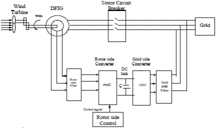
The schematic graph of DFIG based breeze transformation framework with1 powerful rotor side converter is appeared in Figure1. The breeze framework comprises of wind turbine, DFIG, rotor side converter, DC connection and lattice side converter. DFIG essentially comprises of stator and rotor three stage windings2 which are invigorated independently and the two windings can supply vitality bidirectional. The rotor windings can be associated in delta or star.
Wind Based Doubly Fed Induction Generator for
Effective Rotor Side Converter Control
Figure 1: Representation of DFIG wind system.
Stator is empowered by the matrix at steady adjusted three stage supply and the rotor is stimulated by consecutive converter at steady adjusted three stage supply however autonomously from the stator. Relentless state voltage conditions of stator and rotor are exhibited in following conditions Stator voltage conditions:
(1)
2)
(3)
4)
(5)
(6)
(7)
(8)
(9)
(10)
(11)
III. MATHEMATICALDEMONSTRATIONOFRSC The power circuit of RSC topology appeared in Figure 2 is made out of six controlled switches and rotor input channel. Air conditioning side sources of info are perfect three-stage symmetrical rotor voltages, which are separated by obstruction and inductance, at that point associated with three stage compelling rotor side converter comprise of six IGBTs and diodes in against parallel [1]-[5]. The yield is made out of DC connect capacitance and inverter parameters. The model of RSC is completed under the accompanying suspicions. 1. The control converter switches are perfect gadgets. 2. All the parameters are linear time invariant. 3. The three stage voltages are adjusted. Figure 2: Rotor side converter representation Equations related to Rotor side Converter are: (12)
(13)
(14)
(15)
(16)
(17)
Where, Vm is Maximum estimation of the rotor input voltage. Cdc interface capacitor. Rf is Resistance of the rotor side channel. Ldc Inductance of the rotor side channel. In the changed state conditions from (15) to (17), the space vector is characterized as X = [ idr iqr Vdc ] and the control input vector u = [ud uq] is the exchanging capacities u = [ua ub uc] is synchronously turning d-q amounts. The point of the model is to accomplish the consistent DC interface voltage and solidarity control factor. It tends to be gotten by controlling the estimation of q-hub current to zero and dc connect voltage follows the given dc interface reference voltage Vdc_ref10 . From the control discernment, demonstrating the rotor side converter in d-q reference outline has the upside of the decreasing the time fluctuating amounts in required state conditions. (18)
[image:2.595.64.283.59.188.2]
International Journal of Innovative Technology and Exploring Engineering (IJITEE) ISSN: 2278-3075, Volume-8 Issue-9S3, July 2019
IV. FEEDBACKLINEARIZATIONTECHNIQUE
A. Input yield criticism linearization
At present, the info yield linearization strategy is used as a plan technique to linearize the non-direct framework. Not at all like direct approximate particles of the interior elements, in info are yield linearization strategy correct state changes utilized to convey the procedure of linearization. Besides the real framework is changed over into least complex shape [11], [23]. In information yield linearization system, choosing the new helper control factors which encourage lessening the following blunder to invalidate the non-linearity [17]-[19]. The non-direct state conditions (15) to (17) of the powerful rotor side converter are revised in the accompanying condition (18). Three amounts f(x), g(x) and X are orchestrated in grid frame and toward the end they are appeared as total condition. This state vector and yield vector y assume an imperative job in finding the estimations of the control signals and there by exchanging signals for rotor side converter. As per the hypothesis of7 input yield linearization one must pick a spurious yield vector y= [y1 y2], reference vector y*= [y1* y2*] and following blunder e = [y - y*].
B. Voltage Control
Utilizing the hypothetical outcomes portrayed in the past segment, we present here an information yield linearizing arrangement, indicated as Iqr Iqr_ref=0 Vdc_ref voltage control [2], [4], [6], [9], for the dc-transport voltage control of compelling rotor side converter with solidarity control factor by picking two diverse sham yield factors. The spurious yield factors are picked as y = [i qr Vdc] since the point is to keep up the DC interface voltage Vdc is equivalent to voltage reference Vdc_ref with q-pivot current iqr is zer o [13], [16]. At that point reference yield vector must be y* = [0 Vdc_ref] as per the strategy of info yield linearization system.
10 20( ) (20)
Now the internal dynamics are
_ 1 2 (21)
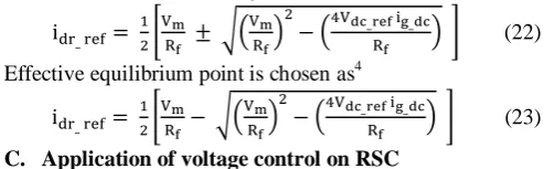
Following blunder e to zero where iqr tends to zero4,12 and DC connect voltage Vdc is ways to deal with DC interface voltage reference. In the wake of getting the zero elements of the framework, two harmony focuses are:
(22)
Effective equilibrium point is chosen as4
(23)
C. Application of voltage control on RSC
The controlling circuit of rotor side converter [3], with information yield direct voltage control is exhibited in Figure3. The Voltage control outline of RSC utilizing Input yield linearization is appeared in Figure 3. Rotor abc voltages
[image:3.595.311.544.389.523.2]and stage edges are considered from stage voltages of DFIG Rotor.
Figure 3: Input Output Linearization Voltage Control of RSC
The three stage abc amounts are changed over into d-q. Rotor d and q-pivot streams are contrasted and d-q reference ebbs and flows. q-hub reference current is taken as zero to encourage solidarity control factor and d-hub reference current is acquired by looking at Vdc and Vdc_ref esteem. From condition (19), ud and uq are found and after that changed to ua, ub and uc. These heartbeat signals are sustained to the Rotor side Converter. The Rotor side converter and Grid side converter switching pattern is represented as
Figure 4: Rotor side converter and Grid side converter switching
V. SIMULATIONRESULTS
The details and circuit parameters utilized in the simulation are given in Table 1. Reenactment aftereffects of unfaltering state and dynamic demonstrating of DFIG, variety of DC connect voltage of rotor side converter with and without controller and impact of parameter vulnerabilities on rotor coordinate hub current and DC interface voltage are displayed in following segment.
A. Steady state and dynamic modeling of the DFIG
[image:3.595.45.292.660.736.2](a): Current ids d-axis
(b): Stator q- axis current iqs
(c): Rotor d- axis current idr
(d): DC Link Voltage Vdc
(e): Speed wm of the DFIG Rotor
(f): Electromagnetic Torque Tm
Fig.5 Consistent state reaction of DFIG framework
B. Voltage with and without controller of DC interface
The reactions of the rotor side converter with and without controllers are appeared in Figure 4. In real framework there are numerous swells in DC
International Journal of Innovative Technology and Exploring Engineering (IJITEE) ISSN: 2278-3075, Volume-8 Issue-9S3, July 2019
[image:5.595.317.537.50.281.2]voltage controller. Yield wave shape is smoothened and keeps up the steady DC connect voltage all through the framework independent of parameter varieties.
Figure 6: Variation of DC Link Voltage Vdc with and without Controller
C. Disturbance thought and parameter uncertainties
At the point when unsettling influence has happened in the framework from 0.1 to 0.12 sec and furthermore between 0.3 to 0.32 seconds the DC connects voltage is fluctuated in a flash amid that period which is appeared in Figure 7(a). If there should be an occurrence of rotor d-hub Current, the impact of unsettling influence is appeared in Figure 7 (b) amid 0.1 to 0.12 sec and 0.3 to 0.32 sec.
(a)
(b)
Figure.7 (a) DC connect Voltage Vdc for annoyance in channel parameter, (b) Rotor d-hub Current idr for
perturbation in filter parameters
Table.1 specifications of the rotor side converter
Power rating 5KW
Source voltage 77.85V
DC Link voltage 75V
Inductor Ldc 0.08H
Resistor Rf 0.01Ω
DC Link capacitor 2.9µF
Frequency 50Hz
Grid side inductor 0.08H
Grid side resistor 0.1Ω
VI. CONCLUSION
This paper proposes a voltage control of DC connect voltage for Effective rotor side converter. Consistent DC interface voltage and solidarity control factor of the framework is accomplished. Dynamic displaying of DFIG and numerical demonstrating of the rotor side converter is introduced. The execution of the viable rotor side converter with and without controller is obviously appeared in recreation results. It is plainly discovered that the control methodology is hearty for the varieties of compelling rotor side channel, DC connect capacitance, uncertainties in the DC interface voltage.
ACKNOWLEDGMENT
[image:5.595.63.271.88.213.2] [image:5.595.53.283.388.616.2]REFERENCES
1. G. abad, J. Lopez, M. A. Rodriguez, L. Marroyo, G. Iwanski, “
Double Fed Induction Machine”, IEEE press.
2. V. Blasko and V. Kaura., “A New Mathematical model and
Control of a three phase AC-DC voltage source Converter”,
IEEE Transactions on Power Electronics., vol. 12, no. 1, pp. 116-123, Jan. 1997.
3. Yang.Ye,M.Kazerani,V.H.Quintana “Modeling,Control and
Implementation of Three phase PWM Converters”, IEEE Transactions on Power electornics,vol.18,no.3,pp 857-863,May 2003.
4. M. T. T sai and W. I. Tsai, “Analysis and design of three-phase
AC-to-DC converters with high power factor and near optimum feed forward,” IEEE Transactions Industrial Electronics, vol.46, pp. 263–273, June 1999.
5. R. Wu, S. B. Dewan, G. R. Slemon, “A PWM ac/dc converter
with fixed switching frequency,” IEEE Transactions on Industry. Applications, vol. 26,pp. 880–885, Sept. 1990.
6. P. Verdelho and G. D. Marques, “DC voltage control and
stability analysis of PWM voltage type reversible rectifiers,” IEEE Transactions on Industrial Electron.,vol.45, pp.263–273, Apr.1998.
7. A .Draou, Y. Sato, and T. Kataoka, “A new state feedback based
transient control of PWM AC to DC type converters,” IEEE Transactions on Power Electronics. vol. 10, pp. 716– 724, Nov. 1995.
8. H.Komurcugil,O.Kukrer,”A Novel Current- Control Method for
Three Phase AC-DC Voltage- Source Converters ”IEEE Transactions on Industrial Electronics,Vol.46,No.3,June 1999.
9. B.Deng Ge Li,J.Wang,X.Wei,Fei Su,” Dynamic Control of
Seizure States with Input Output Linearization Method Based on The Pinsky- Rinzel Model” 7th International conference on Bio Medical Engineering and Informatics 2014.
10. Rusong Wu, Shashi.B.D,Gordon.R.S,”Analysis of a PWM ac to
dc Voltage Source Converter under the Predicted Current Control with a Fixed Switching Frequency” IEEE Transactions on Industry applications,Vol.27,No.4,July/Aug 1991.
11. T.-S. Lee, “Input output linearization and zero dynamics control
of three phase AC/DC voltage source converters”, IEEE Transactions on Power Electronics, vol. 18, no. 1, January 2003.
12. J. Sheok. Kim and S. Ki. Sul, “New control scheme for ac/dc/ac
converter without dc link electrolytic capacitor,” in IEEE pesc’93, Seattle, WA,pp.300-306, June 1993.
13. L. Malesani, L. Rossetto, P. Tenti, and P. Tomasin, “AC-
DC-AC PWM converter with reduced energy storage in the dc link,” IEEE Transactions inIndustry.Applications.,vol.31,pp. 287-292, Mar/Ap 1995.
14. E.sehirli,M.Altinay,”Input- outputLinearization”Kastamonu
University online www.intechopen.com.
15. H.komurcugil,O.kukrer”Lyapunov based control for three phase
PWM AC/DC voltage-source inverters”, IEEE Transactions on Power Electronics,Vol.13,no.5,pp.801- 813,Sep.1998.
16. D.C.Lee,G,M. Lee, Ki-do.Lee, “DC Bus voltage control of
Three phase AC/DC PWM converters using feedback linearization”,IEEE Transactions. Industry. Applications., vol.36, no.3, pp. 826-833, May/June 2000.
17. T.s.Lee,T.kune shiang”Input output Linearization control with
load estimator of Three phase AC/DC voltage source converters”IEEE PSEC,Vol.2,pp.791-795,2002.
18. Shuai, Xiaoping Zhang” Input Output Linearization and
Stabilization Analysis of Internal Dynamics of Three Phase AC/DC Voltage Source Converters” International Conference on Electrical Machines and Systems (ICEMS), 2010.
19. P. Rioual, H. Pouliquen, and J. P. Louis, “Non linear control of
PWM rectifier by feedback linearization and exact PWM control,” in Proc.IEEE PESC’94 Conference, June 1994, pp. 1095–1102.
AUTHORSPROFILE
K. Naresh presently working as Assistant Professor in department of Electrical and Electronics Engineering from Usha Rama College of Engineering and Technology and Pursuing Ph. D from JNTUA Ananthapuramu. He has completed M. Tech from IIT Kharagpur in the Control Stems and completed B. Tech from VIIT in the branch of EEE. He has 20- international publications. His research areas include Power Systems, Control Systems and Renewable Energy Sources.
Dr. P. Umapathi Reddy presently working as Professor in department of Electrical and Electronics Engineering from Sree Vidyanekithan Engineering College and has more than 15-years teaching experience and 9- years research experience. He has published 24- international research papers. His research area includes Power Systems, Control Systems and Renewable Energy Sources.
Dr. P. Sujatha presently working as Professor in
department of Electrical and Electronics