International Journal of Innovative Technology and Exploring Engineering (IJITEE) ISSN: 2278-3075, Volume-8 Issue-12, October, 2019
Abstract—Most interactions between users and augmented reality system (ARS) are that user assigns a marker to ARS, and the ARS responds the marker. In this context, a marker is mapped to an ARS's response, or in general, an array of markers is mapped to an array of ARS's responses. This interaction is a constant or linear complexity interaction since there is only a bijective mapping between a set of markers and a set of ARS's responses. In this research, we propose the expansion of user - ARS complexity into the polynomial. It is an interaction in which not only one marker for a single response (or an array of markers for an array of ARS's responses), but the interaction by which user provides a string of markers as a word of markers (i.e., a combination of multiple markers as a word) for a single ARS's response. The set of strings of markers to the ARS provided by users built a regular language. So that, the complexity of the user-ARS interaction became polynomial. This interaction was implemented by stating the user's language by means of a generalization of finite state automata (gFSA) and placing a universal Turing machine (UTM) between user and ARS, where the UTM as an interpreter translating or mapping the user language to ARS. To summarize our research, overall we apply the idea of a formal language into the interaction between the user and ARS, thereby changing the complexity of the interaction to polynomial even expandable to nondeterministic polynomials.
Keywords: Interpreter, Polynomial interaction, Turing Machine, Word marker
I. INTRODUCTION
In computer programming, augmented reality is a process of combining or “augmenting” video or photographic displays by overlaying the images with useful computer-generated data [1]. Augmented reality views the real world and its objects and augments them. At that time, objects of the real world can be viewed by two different methods and these methods make the augmented reality into the marker based augmented reality and the marker-less augmented reality [2]. Augmented Reality (AR) employs computer vision, image processing and computer graphics techniques to merge digital content into the real world. It enables real-time interaction between the user, real objects and virtual objects. AR can, for example, be used to embed 3D graphics into a video in such a way as if the virtual elements were part of the real environment [3].
A marker is such a sign or image that a computer system can detect from a video image using image processing,
Revised Manuscript Received on August 05, 2019.
Aslan Alwi, Doctoral Student at Computer Science and Electronics Department, Universitas Gadjah Mada, Yogyakarta, Indonesia
(E-mail: [email protected])
Azhari,Lecturer at Computer Science and Electronics Department, Universitas Gadjah Mada, Yogyakarta, Indonesia
Suprapto,Lecturer at Engineering Departement, Universitas Muhammadiyah Ponorogo, Indonesia
pattern recognition, and computer vision techniques. Once detected, it then defines both the correct scale and pose of the camera [3]. Markers can be defined in any feature. Markers can either be 2D images [4], or feature object points [5], or take advantage of local features [6].
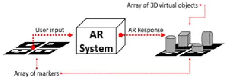
[image:1.595.318.565.340.419.2]The interaction between the user and the ARS in the studies conducted by [7][8][9] and [10], can essentially be seen as an interaction with constant or linear complexity. This is due to a marker given by the user to the ARS, then the ARS provides a response. ARS response can be the addition of 3D virtual objects to reality. Figure 1 shows a simple illustration of the interaction with constant or linear complexity.
Figure 1. User-AR interaction with constant or linear complexity (a marker to a response)
Similarly [2], [11], [12], although they used an array of markers, interactions can also be seen as interactions with constant or linear complexity. This is because for an array of markers there is an array of responses. Only a bijective mapping between markers array to the response array. This user-AR interaction is shown in Figure 2.
Figure 2. User-AR interaction with constant or linear complexity (a markers array to a response array)
In this research, we expanded the complexity of the interaction between the user and ARS. This expansion was indicated at the user's input as a string or word constructed by a combination of multiple markers, in which each word (i.e., markers combination) received an ARS's response or an AR response string (i.e., responses combination). This is not only an array of markers that get an AR response array.
An Interaction Between User and an Augmented
Reality System using A Generalized Finite State
Automata and A Universal Turing Machine
[image:1.595.313.548.543.624.2]Automata and A Universal Turing Machine
Because all words that can be provided by the user are gathered in a set of words that build the language. We give examples of the language it constructs is a regular language, and the automata that accept this language is a generalized Finite State Automata (gFSA). The set of words that build the regular language causes the complexity of interaction between the user and the ARS into polynomial complexity. Not only a constant or linear complexity.
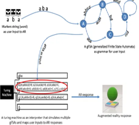
[image:2.595.58.287.202.408.2]As an interpreter between user and ARS, we create a UTM that translates between words provided by the user to the ARS response. Figure 3 shows how these interactions are formed.
Figure 3. Interaction by using a gFSA and a UTM
A thorough description of this interaction is given by Figure 4, where the interpreter is placed in the ARS to translate user input to the desired AR response.
[image:2.595.61.291.583.764.2]Basically, we can expand the complexity of this interaction in various possible complexities simply by building a set of words with appropriate complexity. In fact, we can build a language with nondeterministic polynomial complexity using nondeterministic automata or nondeterministic Turing machine. But in this paper, we are limited to presenting an idea of the interaction built in the regular language.
Figure 4. Interaction with polynomial complexity
II. GENERALIZED FINITE STATE AUTOMATA FOR MARKERS
The background of writing this paper is our attempt to formally formulate marker-based interactions between users and ARS. This attempt sees that the presentation of markers to the ARS can be seen as the presentation of a string (word) to the system. The notion of augmented reality, marker [3], [2] and some previous research on augmented reality as done by [7] and [8] is to use a marker as an input for the interaction between the user and the augmented reality system. We seek to expand the complexity of this interaction by using markers string. Some other studies also use more than one marker in the form of a marker matrix [2], [11] or [12] but are not intended to build a word marker for the purpose collectively in which all word sets build an interaction language. Our study is also not intended to provide new functions [10], [13] and [14], new AR frameworks at the top level such as [15], [16] and [17], or offer a way of registering images at low levels of AR such as [18] or the introduction of a marker image [19]. This research proposes a formal form of interaction between user and ARS by viewing input by a user to ARS is a word marker that builds an interaction language.
The interaction between the user and the ARS in the form of a word from the marker necessarily requires a formality that sees the set of markers is a language. Therefore, as our first attempt to formally handle this interaction is to build finite state automata that can accept the word marker. However, this marker input is a word representation (markers string). Therefore, we are inspired to use generalized finite state automata as automata that can read the input of the marker's string presentation. Generalized finite state automata (gFSA) are finite state automata (FSA) whose input is generalized to a word, not only a character. The formal definition for gFSA is presented in the definition 1 from [20]:
Definition 1. A generalized finite state automaton (gFSA) is a triple M = (G, S, Y). Here G = (V, E, ϕ) is a labeled directed finite graph where the labeling ϕ assigns to each e
∈ E, a language Le. S ∈ V is the start state. Y ⊂ V is the set of accept states.
International Journal of Innovative Technology and Exploring Engineering (IJITEE) ISSN: 2278-3075, Volume-8 Issue-12, October, 2019
Figure 5. Generalized Finite State Automata to accept markers string.
III. TURING MACHINE THAT CAN SIMULATE ALL GFSA
In this section, first, we expressed intuitively how to create an interpreter machine that can receive and simulate all possible gFSA. The notion is put forward intuitively in the sense that a Turing machine is created without introducing gFSA encoding into an alphabet and then fed into a Turing machine. Our goal is to make it easier to introduce this Turing machine. Secondly, we wrote it in a formal form with the input encoding of the Turing machine so that it meets a formal definition. The construction of a Turing machine that can accept all of the gFSA is expressed intuitively as follows:
a. Initialization:
Step 1:M Write start state on the first cell of T4.In the example, start state is A.
Step 2:M writes the gFSA input string in T1, starting from the first cell.Suppose the input string for gFSA is acdaabcdb.
Step 3:M empty T3.
Step4:M Write all gFSA instructions on T2, starting first cell.The gFSA instruction set in the example of Figure 5 is: {q1(A, abbcd) = B, q2(A, acda) = B, q3(A, aba) = C, q4(B, abcd) = D, q5(D, B) = D, q6(B, bd) = C, q7(C, ccd) = D}.
Step 5:M positions all 4 heads to the first cell position of each tape.
b. Simulation of gFSA by M:
Step 1:M reads the cell that is being pointed by the head on T1. In the example when the initialization is pointing to the first cell that is the character a.
Step 2a:M reads the cell that is being pointed by the head in T4.If the designated state is FINISH state and the cell designated by the head in T1 is the empty cell, thenHALT.If the designated state is not a FINISH state and the cell pointed to by head in T1 is an empty cell, then FAIL and HALT.In the example,the initialization is pointing to the first cell (state A).
Step 2b:If T3 is not empty, compare the state read in step 2a and the characters read in step 1 with the first instruction in T3. If the state of the firstinstruction argument is the same as the current state instep 2a and the first character in the word of the first instruction argument is the same as the character read in step 1, then go to step 5.
Step 3:M searches for all instructions in T2 whose initial input character is being pointed by the head of T1, and its current state is the state that is being designated by the head in the previous onthe first cell of T4.If not found any instructions then FAIL and HALT.In the example, after searching to find state A and character a at the beginning we get the set of instructions {q1(A, abbcd) = B, q2(A, acda) = B, q3(A, aba) = C}.
Step 4:M empty T3 and M copy all the instructions found in step 3 and then write them sequentially to T3, the written sequence starting from the largest string length of the instruction input.Then head on T2 back to the first cell positionand head on T3 back in first cell position.In the example, after being sorted, the instructions are:q1(A, abbcd)=B, q2(A, acda)=B, q3(A, aba)=C.
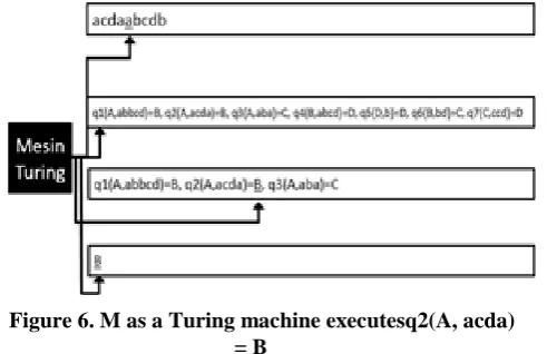
Step 5:M starts reading instructions sequentially starting first instruction on T3, and comparing its contents with T1. (Note: in this T3, M no longer performs searching, but reads in sequence starting with the first instruction). If the word input in the first instruction does not match the word in the input section of T1, then the head moves on the second instruction. The word input in the second instruction is compared to the word in the input section of T1, if not match then the head moves to the third instruction, and so on until the match is found.If the instructions on T3 are read out and no matching instructions are found, then FAIL and HALT. If a matching instruction is found then the transition state of the instruction is written in T4.In the previous example, the instruction that matches the string input with string in T1 is q2(A, acda) = B, then M executes q2(A, acda) = B, then obtains state B as the following state. State B is then written on T4, overwriting state A on the first cell of T4.Illustrations for this example are as follows Figure 6:
Figure 6. M as a Turing machine executesq2(A, acda) = B
Step 6: Repeat steps 1 through 5. FINISH.
IV. UNIVERSAL TURING MACHINE FOR GFSA
[image:3.595.314.560.453.612.2]Automata and A Universal Turing Machine
4.1. Generalization of gFSA as a Turing machine
The proposed Turing machine M is presented intuitively to simulate any gFSA. M is formally formulated by encoding each gFSA input and every gFSA instruction. Then we will show that M is universal or a universal Turing machine (UTM) by demonstrating that M can also simulate a standard Turing machine. If M can simulate a standard Turing machine it can automatically simulate the entire Turing machine and algorithm, based on Church-Turing thesis.
The work to create a universal Turing machine has become an intellectual challenge for many people, in the past, A.M. Turing himself put forward the idea of automated machines [21], as Stephen Dolan did, which shows that only mov commands along with the registers on the x86 processor machine can be proven as complete Turing [22] so it can be used to build a Universal Turing machine, which means it can simulate the whole algorithm. Similarly, Minsky [23] has tried to prove that a counter machine or register machine can be a universal Turing machine with the minimum number of instructions possible.
It is not formal at all. Here, we try to prove formally that the M that has been previously mentioned is also able to simulate all gFSA and standard Turing machine as well. So, it is sufficient to be proclaimed as a universal Turing machine or UTM. In this work, we first generalize gFSA into a Turing machine whose instructions execute the word, not only executing a symbol of the tape but a word from the tape. From this generalization we expect two implications, that is, we can prove formally a UTM machine that simulates all forms of gFSA as well as trivially means it can simulate all forms of standard Turing machines. For this, first, we have to rewrite the definition of gFSA in Definition 1 into Definition 2.
Definition 2. A generalized-FSA (gFSA) is 6-tuple (Q, Σ,q0, LΣ, δ, F) where :
Q Is a finite set of states Σ Is the set of input symbols q0 Is the initial state
LΣ = { a1a2a3...an | ai Σ } δ: Q x LΣ Q
F ⊂ Q Is the set of final states.
The gFSA in Definition 2 is then generalized into a Turing machine executing the word on the tape. For this work, we first create a set of symbols for inputs and tape for the Turing machine. Let C be the alphabetical set of keyboards (typewriters) without blank symbols. That is C = {a, b, c, d, e, f, g, ..., y, z, A, B, C, D ..., Z, 1,2,3,4 ..., 9, + _) (*, &, %, $, £, @ ...}, suppose the blank symbol is . Definition 3 shows the formal definition of kind of Turing machine.
Definition 3. A Turing machine MW that executes a word is defined as a 7-tuple (Q, Σ, I, LI, q0, δ, F) where:
Q Is a finite set of states F ⊂ Q Is the set of final states. q0 Is the initial state
I = C alphabet
Σ = C ∪ {} Is the set of tape symbols LI = { a1a2a3...ag | ai I , i=1,2,3,...,g} δ: Q x LI Q x LI x {-m,0,n}
MW has only one tape, reads from left to right, and writes from left to right.
The work of the MW transition machine can be explained. Suppose a transition δ1(A, abcd) = (B, cda, -2) is read as follows: The head reads the word abcd in the tape, so it moves from state A to state B, then head reset to the start position of word abcd and starts writing word cda overwrite word abcd then move 2 cells to left. Suppose a transition δ2(A, aaac) = (B, aadcda, 2) is read as follows: The head reads the aaac word in the tape, then the MW moves from state A to state B, then head reset to the initial position of word aaac and starts to write word aadcda, overwrite all aaac cells then move 2 cells to the right. By taking MW as (Q, Σ, I, LI, q0, δ, F) where we define the transition is δi(Ai, x) = (Aj, x, 1) in general for MW, where x is a word, then MW is a gFSA as defined in the definition 2. But maybe gFSA has a symbol outside C, to overcome it, encoding x into word in C so the transition becomes δi(Ai, encode(x)) = (Aj, encode(x), 1).
4.2. Encoding for MW and its input
MW and input encoded into alphabet C. This encoding is a description of MW and also a description of the MW input to be supplied into an expected universal Turing machine. The encoding is as follows: All states of MW are mapped into integers 0, 1, ... k., Mapping is done by bijective where the initial state q0 ≡ 0, and the final states are f, f + 1, ... k for 0<f ≤ k.So that Q = {0,1,2, 3, ...k}, q0 = 0 and F = {f, f + 1, ...k} k ≥ 0, f ≤ k.
Word which is the input of MW is encoded into C ∪ {} bijectively, so we get an encoding language that is Lencode = encode(LI) = {b1b2b3 ... bg | bi = encode (ai), ai I, biC∪ {} i = 1,2,3, ..., g}.The transition function is expressed as δ-function: δ (q, s) = (q ', s', d) where s, s' ∈ Lencode, 0≤ q ≤ f and d∈ {-m, 0, n}, 0 ≤ q'≤ k.The length of the word s ∈
Lencode is |s|.Next, the δ-function into our UTM Turing machine is described in 6-tuples (q, s, |s|, q ', s', d).Thus, writing the description of MW into the UTM tape is k, f, t1, t2, t3, ... where k is the number of states, f is the first final state and ti is (q, s, | s |, q ', s', d).This means encoding(MW) = k, f, (q, s, |s|, q ', s', d), ..., (q, s, |s|, q ', s', d)where n, f, q,
q ', d are integers.
0≤ f, q <f, q '≤ k,d ∈ {-m, 0, n}s, s' ∈Lencode.
4.3. UTM Construction for MW
International Journal of Innovative Technology and Exploring Engineering (IJITEE) ISSN: 2278-3075, Volume-8 Issue-12, October, 2019
a. Initialization:
Step 1: M Write 0 on the first cell of T4. (0 is a state start) Step 2: M writes the encoding of the MW input string in T1, starting from the first cell.
Step 3: M empty T3.
Step 4: M Write all the encoding(MW) on T2, start the first cell.
Step 5: M positions all 4 heads to the first cell position of each tape.
b. MW simulation:
Step 1: M reads the cell that is being pointed by the head on T4.If q> f then HALT. The instruction reaches the final state.If q <f then goes step 2.
Step 2a: M reads the cell that is being pointed by the head on T1.
Step 2b:If T3 is not empty, compare the state read in step 1 and the characters read in step 2a with the first instruction in T3. If the state of the first instruction argument is the same as the current state instep 1 and the first character in the word of the first instruction argument is the same as the character read in step 2a, then go to step 5.
Step 3: M searches for all instructions in T2 whose initial input character is currently designated by the head of T1, and its current state is the state that is being designated by the head in T4.If no matching instruction is found then HALT and FAIL.If found then go to step 4.
Step 4: M empty T3 and M copy all the instructionsfound to match in step 3 and then write it sequentially to T3, written sequence starting from the largest string length of input from the instruction by reading the value of |s| on (q, s, |s|, q', s', d).Then head on T2 back to the first cell position of T2 and head on T3 back in first cell position of T3.
Step 5: M starts reading the first instruction on the order in T3 and compares the first instruction word input with word on the input piece in T1.(Note: in this T3, M no longer performs searching, but only reads in sequence starting with the first instruction).
If the word in the first instruction does not match the word on the input piece in T1, then the head moves on the second instruction in the sequence, then do a word comparison with the word on the piece of input in T1, if it does not match then move to the third instruction, and so on until found match.
If the instructions on T3 are read out and no matching instructions are found, then HALT and FAIL.
If a matching instruction is found (q, s, |s|, q ', s', d) where word s match with the word being pointed at the input piece in T1, then the transition state q' of the instruction is written on T4. The current state is transformed into the transition state q'.The head then goes to the first character of the word s in the input piece in T1, then starts overwriting s by writing word s' to the right until it finishes.After s'finished writing then start at the end character s', head on the T1 move as far as d cell.
Step 6: Repeat steps 1 through 5. FINISH.
Furthermore, by making the size of each word in MW that s is 1, |s| = 1, then MW is a standard Turing machine, it trivially proves that M Turing machine construction is a Turingcomplete, a universal Turing machine (UTM).
V. FORMAL PROOF USING MATHEMATICAL INDUCTION& RESULTS
We want to show that M as a universal Turing machine can be formally proven through mathematical induction. The proof scenario is as follows:
First, we declare each MW transition function δ(q, s) = (q', s', d) into 6-tuples (q, s, |s|, q', s', d). We denote p as an instruction where p = (q, s, |s|, q', s', d) and |s| Is the length of word s.
For each input given to MW, the MW generates a run (sequence of instructions) that executes the input until it is complete. Suppose the run for MW is expressed as rMW = p0, p1, p2, p3, ..., pk, where pi=(qi, si, |si|, qi', si', di), and for an input w = w1w2w3...wh where wi is the i-th word, i = 1,2,3, ...h, run for input w is written as rMW(w). The interpretation of rMW(w) is that MW executes the input w in a series of transitions in the form of a rMW instruction execution sequence.
Simply, we say M can simulate MW if M can also generate series of rMW instruction execution. That is M can also produce rMW(w) exactly the same.In general, suppose rM is a series of instructions executed by M, M can simulate MW if only if for every w input MW, so that rMW(w) then M can produce rM(w), where rMW(w)=rM(w).
More generally, let α be a bijective encoding function, such that let pi be the i-th instruction, α(pi)=α(qi,wi,|wi|,qi',wi',di)=(α(qi),α(wi),α(|wi|),α(qi'),α(wi'),α (di)), and rMW are expressed as sequences of instructions running in sequence, i.e. rMW = p0,p1, p2,p3,...,pk then the α encoding of rMW is α(rMW)=α(p0),α(p1),α(p2),α(p3),...,α(pk),by using the α encoding function we can formulate the generalization of the MW simulation as follows:
Definition 4. Turing machine M is said to be able to simulate MW if only if for every w input of MW, so that rMW(w) and α is a bijective encoding function, then M can produce rM(s) where α(rMW)=rM and s=α(w).
By using definition 4, furthermore, we can prove that the Turing machine M we have previously constructed is a universal Turing machine. This argument can be stated as follows:
Theorem 1. M is a Turing machine that can simulate MW. Proof:
Previously when the M Turing machine was constructed, we have shown an encoding function that maps every state symbol to a number in C ∪ {}, and each tape symbol to C
Automata and A Universal Turing Machine
That means we want to prove that for rMW = p0, p1, p2, p3,..., pk it follows that α(pi)=pi’ where rM = p0’, p1’, p2’, p3’, ..., pk’. i=1,2,3,...,k. For this proof, pi = (qi,wi,|wi|,qi',wi',di) are encoded into pi'=α(pi) consistent with the previous M constructs. This encoding is written as follows:
pi’= α(pi)= α(qi,wi,|wi|, qi’,wi’,di)=( α(qi), α(wi), α(|wi|),
α(qi’), α(wi’), α(di)) (1)
To be compatible with MW encoding in the previous M, for each state of MW encoded to a number ands= α(w), s is a string constructed from C ∪ {}, then the above encoding equation (1) is:
pi’= α(pi)= α(qi,wi,|wi|, qi’,wi’,di)=( α(qi), α(wi), α(|wi|), α(qi’), α(wi’), α(di))=(mi, si, |si|, mi’,si’, di) (2)
where mi, si, mi’, si’, di Lencode For k = 0:
In iteration k = 0 of the algorithm M is the initialization steps as follows:
Initialization:
Step 1:M Write 0 on the first cell of T4. (0=α(q0) is encoding for start state)
Step 2:M writes the MW input string encoding in T1, starting from the first cell.(s = α(w) on T1,s=s1s2s3...sh=α(w1)α(w2)α(w3)...α(wh)=α(w))
Step 3: M empty T3.
Step 4:M Write all the encoding(MW) on T2, start the first cell.(M writes all pi'= α(pi) for the entire MW instruction pi).
Step 5: M positions all 4 heads to the first cell position of each tape.(Word s0 being pointed by the heads of T1 and 0 designated by the heads of T4 referring to the arrangement of (0,s0,?,?,?,?). But in T3 there are instructions (0,s0,|s0|,m0',s0',d0) corresponds to (0,s0,?,?,?,?) As a consequence of step 4). Based on this step 5 for p0 = (q0, w0, |w0|, q0’, w0’, d0)where q0, q0'are states of MW and w0, w0' is the input and output word of MW, d0 is the movement of the head in the MWtape, then we get p0'=(0, s0, |s0|, m0', s0', d0) in step 5. That is:α(p0)= α(q0,w0,|w0|,q0’,w0’,d0)= (α(q0), α(w0), |α(w0)|, α(q0’), α(w0’), α(d0)) = (0,s0,|s0|,m0’,s0’,d0)=p0’consistent with equation (2). That is α(p0)=p0’
Thus, we have proved that for rMW = p0then rM= α(rMW)= α(p0)=p0’ dan s0= α(w0)is consistent with definition 4.
For k = n:
Suppose that in iteration k = n the algorithm M applies
α(pn)=pn'and sn=α(wn) is true, i.e.α(pn)=
α(qn,wn,|wn|,qn’,wn’,dn)= (α(qn), α(wn), |α(wn)|, α(qn’), α(wn’), α(dn)) = (mn,sn,|sn|,mn’,sn’,dn)=pn’.That is, the machine can produce pn'which is the one-to-one equivalent of pn. i.e. pn'=α(pn) where α is bijective.That is,rM=α(rMW)=α(p0,p1,p2,...,pn)=α(p0),α(p1),α(p2),...,α(pn)=p0' ,p1',p2',...,pn'and s=α(w) are consistent with definition 4.
For k = n + 1:
We want to show that at iteration k=n+1, it is also true that α(pn+1)=pn+1'and sn+1=α(wn+1). By using M algorithm, MW simulation in k=n + 1 is:
Step 1:M reads the cell that is being pointed by the head on T4.(Since the n-th iteration is true ie α(pn) = pn'and sn = α(wn), then at k = n + 1 iteration, the head of T4 denotes the current state mn'). If mn'>f then HALT. The instruction reaches the final state.(Due to the bijective nature of α, the inverse mn’ is a final state in MW, this means MW is also HALT). If mn'<f then goes step 2a.
Step 2a:M reads the cell that is being pointed by the head on T1.(At the iteration k = n + 1, T1 denotes the first character of word sn+1, since s=s1s2s3...sh= α(w1)α(w1)α(w1)...α(wh)= α(w) maka sn+1= α(wn+1)).
Step 2b: If T3 is not empty, compare the state read in step 1 with the state on the first instruction and the first character read in step 2a with the first character in the word input of the first instruction in T3.(That is, the current state is mn'in T4, and head on T1 denotes sn+1 initial character. If pair (mn', sn+1, ?, ?, ?, ?) does not match with the first instruction then go to step 3, if (mn', sn+1, ?, ?, ?, ?) match with the first instruction then go to step 5)
Step 3:M searches for all instructions in T2 whose initial input character is currently designated by the head of T1, and its current state is the state that is being designated by the head in T4.If no matching instruction is found then HALT and FAIL.(That is, if no matching instruction is found with the pair(mn', sn+1, ?, ?, ?, ?) then HALT and FAIL. Since all of the MW instruction encoding is written on T2 and based on the bijective properties of α then this means there is also no instruction on MW that can execute inverse from(α -1(m
n'),α-1(sn+1),?,?,?,?), this means MW is also HALT or FAIL).
If found then go to step 4.
Step 4:M empty T3 and M copy all instructions found match on step 3 and then write it sequentially to T3, written sequence starting from the largest string length of input from instruction by reading value |s| on (q,s,|s|,q',s',d).Then head on T2 back to the first cell position of T2 and head on T3 back in first cell position of T3.
Step 5:M starts reading the instruction in the first sequence of T3 and compares its word input with T1.If the instructions on T3 are read out and no matching instructions are found, then HALT and FAIL.(That is, if no matching instruction is found with the pair(mn', sn+1, ?, ?, ?, ?) then HALT and FAIL. Since all of the MW instruction encoding is written on T2 and based on the bijective properties of α then this means there is also no instruction on MW that can
execute inverse from
(α-1(mn'),α-1(sn+1),?,?,?,?), this means MW is also HALT or FAIL).If an instruction is found matching with (mn', sn+1, ?, ?, ?, ?), that is(mn’,sn+1,|sn+1|,mn+1’, sn+1’, dn+1), no matter that MW is deterministic or nondeterministic then the inverse (mn’,sn+1,|sn+1|,mn+1’, sn+1’, dn+1)must exist due to the bijective α properties and because all MW instruction written in T3that is:(α-1(mn’), α-1(sn+1),| α-1(sn+1)|, α-1(mn+1’), α -1(sn+1’), α-1(d
n+1))=(qn+1,wn+1,|wn+1|,qn’,wn+1’,dn+1)=pn+1 Step 5 proves that for the iteration k = n + 1, it is obtained:
rM=α(rMW)=α(p0,p1,p2,...,pn,pn+1)=α(p0),α(p1),α(p2),.. .,α(pn),α(pn+1)=p0’,p1’,p2’,...,pn’,pn+1’ and s=α(w) consistent with definition 4.
Step 6: Repeat steps 1 through 5. FINISH.
International Journal of Innovative Technology and Exploring Engineering (IJITEE) ISSN: 2278-3075, Volume-8 Issue-12, October, 2019
Theorem 1 has been proven. Trivially we can then state the following theorem:
Theorem 2. The M machine that can simulate MW is a universal Turing machine.
Proof:
Take for example w=w1w2w3...wh is the MW input such that |wi|=1 for every i = 1,2,3, ..., h, and d = {-1,0,1} is the movement of the head tape, then MW is a standard Turing machine. By using Theorem 1, then Theorem 2 is proved.
VI. CONCLUSION
This paper showed that a user-ARS interaction with polynomial complexity can be constructed using gFSA and there can also constructed an interpreter for interaction using a UTM.
REFERENCES
1. W.L. Hosch, augmented reality | computer science | Britannica.com, Encycl. Br. Inc. (2017) 1. https://www.britannica.com/technology/augmented-reality (accessed September 1, 2017).
2. D. Kim, W. Moon, S. Kim.A Study on Method of Advanced Marker Array, Int. J. Softw. Eng. Its Appl. 8 (2014) 1–16
3. S. Siltanen, Theory and applications of marker-based augmented reality, JULKAISIJA – UTGIVARE – PUBLISHER, 2012. http://www.vtt.fi/publications/index.jsp
4. A.F. Waruwu, I.P.A. Bayupati, I.K.G. Darma Putra. Augmented Reality Mobile Application of Balinese Hindu Temples : DewataAR, Ijcnis. (2015) 59–66. doi:I. J.Computer Network and Information Security.
5. D. Pawade, A. Sakhapara. Augmented Reality Based Campus Guide Application Using Feature Points Object Detection, Ijitcs. (2018) 76–85. doi:10.5815/ijitcs.2018.05.08.
6. F. Khalifa, N. Semary, H. El-Sayed, M. Hadhoud.Local Detectors and Descriptors for Object Class Recognition, Ijisa. (2015) 12–18. doi:10.5815/ijisa.2015.10.02. 7. G. D, O. Kumar, S. Ram. Marker Based Augmented
Reality Application in Education: Teaching and Learning, Int. J. Res. Appl. Sci. Eng. Technol. 4 (2016) 153–158. www.ijraset.com
8. M. Shetty, V. Lasrado, R. Mohammed. Marker Based Application in Augmented Reality Using Android, Int. J. Innov. Res. Comput. Commun. Eng. Vol. 3 (2015) 146– 151
9. J.M. Mota, I. Ruiz-Rube, J.M. Dodero, I. Arnedillo-Sánchez. Augmented reality mobile app development for all, Comput. Electr. Eng. 65 (2018) 250–260. doi:10.1016/j.compeleceng.2017.08.025.
10. A.K. Sin, H.B. Zaman. Tangible Interaction in Learning Astronomy through Augmented Reality Book-Based Educational Tool, IVIC 2009, LNCS 5857, Springer-Verlag Berlin Heidelb. 2009. (2009) 302–313.
11. D. Student, V. Gediminas. An Efficiency Analysis of Augmented Reality Marker Recognition Algorithm, Electr. Control Commun. Eng. Gruyter Open. (2014). doi:10.2478/ecce-2014-0008.
12. K. Tateno, I. Kitahara, Y. Ohta. A Nested Marker for Augmented Reality, ResearchGate. (2017). doi:10.1109/VR.2007.352495.
13. Y. Yao, X. Pang, Q. Lu, Q. Hu.Augmented Reality Interactive Interface for Defective Bone Repair System, APCMBE 2008, IFMBE Proc. 19, Springer-Verlag Berlin Heidelb. 2008. (2008) 733–736.
14. M. Ilievski, V. Trajkovik.An Approach to Both Standardized and Platform Independent Augmented Reality Using Web Technologies, ICT Innov. 2012, AISC 207, Springer-Verlag Berlin Heidelb. 2013. (2013) 195– 203. doi:10.1007/978-3-642-37169-1.
15. Q. Zhang, M.S. Lew. The Leiden.Augmented Reality System ( LARS ) Leiden Augmented Reality System ( LARS ), Springer-Verlag Berlin Heidelb. 2012. (2012) 639–642.
16. L. Vera, J. Gimeno, I. Coma, M. Fernández, Augmented Mirror . Interactive Augmented Reality System Based on Kinect, INTERACT 2011, Part IV, LNCS 6949, IFIP Int. Fed. Inf. Process. 2011. (2011) 483–486..
17. RafałWojciechowski, Modeling Interactive Augmented Reality, Springer-Verlag London Limited 2012 137, 2012. doi:10.1007/978-1-4471-2497-9..
18. A. Pagani.Modeling Reality for Camera Registration in Augmented Reality Applications, Springer-Verlag Berlin Heidelb. 2014. (2014) 321–324. doi:10.1007/s13218-014-0320-5..
19. D. Bradley. Adaptive Thresholding using the Integral Image, J. Graph. Tools. Vol. 12, Issue 2. (2013). doi:10.1080/2151237X.2007.10129236.
20. A.P. Sánchez, M. Shapiro, Growth in higher Baumslag-Solitar groups, arxiv1605.01131v4. (2016) 1–17. http://arxiv.org/abs/1605.01131
21. A.M. Turing, On computable numbers, with an application to the entscheidungsproblem. a correction, Proc. London Math. Soc. s2-43 (1938) 544–546. doi:10.1112/plms/s2-43.6.544.
22. S. Dolan, mov is Turing-complete, Cl.Cam.Ac.Uk.
(2013) 1–4.
http://www.cl.cam.ac.uk/~sd601/papers/mov.pdf.