J Leach1,3, M R Dennis2, J Courtial1 and M J Padgett1
1Department of Physics and Astronomy, University Avenue, Kelvin Bld,
Glasgow G12 8QQ, UK
2School of Mathematics, University of Southampton, Highfield SO17 1BJ, UK
E-mail:[email protected]
New Journal of Physics7(2005) 55
Received 11 November 2004 Published 15 February 2005 Online athttp://www.njp.org/ doi:10.1088/1367-2630/7/1/055
Abstract. Optical vortices generically arise when optical beams are combined. Recently, we reported how several laser beams containing optical vortices could be combined to form optical vortex loops, links and knots embedded in a light beam (Leachet al2004Nature432165). Here, we describe in detail the experiments in which vortex loops form these structures. The experimental construction follows a theoretical model originally proposed by Berry and Dennis, and the beams are synthesized using a programmable spatial light modulator and imaged using a CCD camera.
Optical vortices (phase singularities, wave dislocations) are ubiquitous in nature, occurring whenever three or more light waves interfere. They are places in the interference field where the intensity is zero and the phase is undefined, usually occurring at points in two-dimensional fields and along lines in three dimensions (see, for example, [1]–[3]). Within the laboratory, vortices are commonly produced using computer-generated holograms or diffractive optics. Holograms of the design, originally demonstrated by [4,5], are now widely used to create light beams with vortices embedded, and the orbital angular momentum [6]–[8] with which they are associated. In 2001, Berry and Dennis [9, 10] showed theoretically that specific superpositions of beams could be generated, in which vortex loops could be linked together and even knotted. Here, we describe in detail our experimental generation [11] of such laser beams.
An optical vortex embedded on the axis of a laser beam is usually characterized by a function, R|l|exp(ilφ)describing the local structure of the optical field around the vortex point in a transverse cross section of the beam. The exp(ilφ) factor describes the phase singularity nature of the vortex,R|l|shows that this must be accompanied by a zero of intensity. The integerl determines the number of phase cycles made in a right-handed circuit of the vortex and is called the strength of the singularity. Althoughlcan take any integer value, positive or negative, vortices
3 Author to whom any correspondence should be addressed.
with|l|>1 are unstable and, in the presence of astigmatism, degenerate to form multiple vortices ofl= ±1 upon propagation. Many observations have been reported on the seeming interaction between two or more vortex points as light propagates from one plane to the next (see, for instance, [12] and references therein). In this view, two vortices with oppositely signedl may spontaneously appear together in one plane, propagate to a subsequent plane, and then recombine (birth/creation and death/annihilation of vortices). In identifying propagation of the beam with temporal evolution, this language is possibly misleading since the optical beam is static in time in the laboratory reference frame.
A different physical description is to recognize that the pair of vortices forms a looped thread within the beam (see, for example, [13]). An arbitrary light field, such as a space-filling speckle pattern, contains many optical vortex lines in a complicated arrangement [14]. As parameters vary, the vortex lines evolve in a complicated way, and may reconnect, and loops may appear or disappear [1,10,15,16].
The original analysis of knotted and linked optical vortex loops [9] used a combination of Bessel beams [17]. From an experimental standpoint, this construction has two problems: firstly, that ideal Bessel beams have infinite aperture (their transverse profile, specified by aJl Bessel function, is infinitely extended); secondly, that the range of intensity in the proposed beams was too large to observe the faint light around the knotted and linked dark threads. The construction was later extended [10] to give the same topological structures within paraxial beams, allowing the possibility of knotted dark structures within Laguerre–Gaussian beams [6], with fixed frequency specified by the wavenumber k. In cylindrical coordinates R, φ, z, these have the normalized form
ψlp(R, φ, z;w)=
p! π(|l|+p)!
R|l|exp(ilφ) (w2+ iz/ k)|l|+1exp
−R2
2(w2+ iz/ k)
×L|pl|
R2 w2+z2/ k2w2
w2−iz/ k w2+ iz/ k
p
, (1)
whereLdenotes the generalized Laguerre polynomials. In addition to an axial optical vortex of strengthl, there are two other parameters that may be varied—the radial numberp,which is an integer determining the order of the Laguerre polynomial (effectively, the number of nodal rings about the beam axis), and the waist width w,which is a continuous variable setting the finite transverse width of the beam. These additional degrees of freedom allow us to create the same topological structures, but with a reduced range of intensity, enabling the nodal structures to be unambiguously seen.
We synthesize the link and knot by superposing three Laguerre–Gaussian beams with the same indexl,giving the fieldψunpert,then perturbed by another Gaussian beamψpertwith index
l =0.Therefore, the knot and link fieldsψknot,linkare equal to the sumψunpert+ψpert.The values of
the amplitudes, indicespand waist widthswof the components of the unperturbed superposition ψunpert are chosen so that at a specific radiusR0 in the waist plane, both the field and its radial
derivative are zero, i.e.
ψunpert(R0)=0, ∂Rψunpert|R0 =0. (2)
the other two, which share the same smaller radius, are symmetrically arranged on either side of this plane. The fact that the radial derivative vanishes on the central vortex ring (z=0, R =R0)
means that it has zero strength—it can be thought of as two superposed vortex rings with opposite strengths. The numerical value ofR0and particular choices ofpandwin the superposed beams
are chosen such that the intensity is relatively bright in the regions separating the three vortex rings from each other and from thel-fold singularity on the axis.
To this superposition is added a simple Gaussian perturbing beam ψpert with near planar
phasefronts (i.e. wide waist). As the amplitude of the perturbing beam increases, the configuration of three vortex rings deforms through a sequence of reconnections (explained in detail in [10]) to give an(l,2)torus knot [18]. Therefore, the total superposition of beams we used is
ψlink,knot(x, y, z)=ψunpert+ψpert
=a1ψl0(x, y, z;2w0)+a2ψl0(x, y, z;w0)
+a3ψl1(x, y, z;w0)+apertψ00(x, y, z;8w0). (3)
The superposition of beams with amplitudes a1,2,3 form ψunpert, satisfying the conditions (2)
above. For convenience,a1=1,andw0is a fixed transverse lengthscale of the beam, chosen in
our experiment to be 1 mm. The link, depicted later in figures4and6, was formed withl=2,and the relative amplitudes:a2 = −0.35, a3 =0.36, apert =0.35 (which gaveR0 =2w0). The knot
of figures5and7was formed withl=3,and relative amplitudesa2 = −0.26, a3=0.29, apert =
0.25 (which gaveR0 =2.2w0). Ifl =1 the ‘torus knot’ is a single loop, wrapped twice around
the vortex axis, which will not be described further. The beam combinations we have chosen, satisfying the general conditions of [10], are not unique (two equations are solved, but three parameters (a2, a3 and R0) are varied; also, the values of p and w can be changed). They are
convenient in that they are straightforward to implement and the resulting intensity range makes it possible to image the singularities. Adjustment of the superposition numerically reveals that the link occurs for values of the relative perturbation amplitude apert between 0.3 and 0.5, and
the knot for values between 0.22 and 0.4. Both the knot and link are stable between similar finite ranges of their various parameters.
As discussed above, vortex carrying beams can be easily created within the laboratory using diffractive optical components. For example, if a diffraction grating is modified such that the lines near its centre combine to form a fork dislocation, then the first-order diffracted beam contains an optical vortex. The strengthlof the vortex is equal to the order of the fork dislocation. In addition,pcircular discontinuity or discontinuities can be added to these designs to give the radial index of the resulting beam [19]. Although a hologram of this kind provides precise control over the phase of the diffracted beam, the intensity distribution depends also on the profile of the illumination beam. It transpires that for a simple single-forked hologram design, illumination by a fundamental Gaussian mode gives anl=1 vortex beam in the far field, which has over 80% of its energy in thel=1, p=0 Laguerre–Gaussian mode. Although satisfactory for many studies and applications, this level of mode purity is insufficient to form the topological structure we desire.
+
Desired phase Carrier phase Combined phase
Desired intensity Hologram mod 2π
[image:4.595.82.526.85.334.2]0 2π
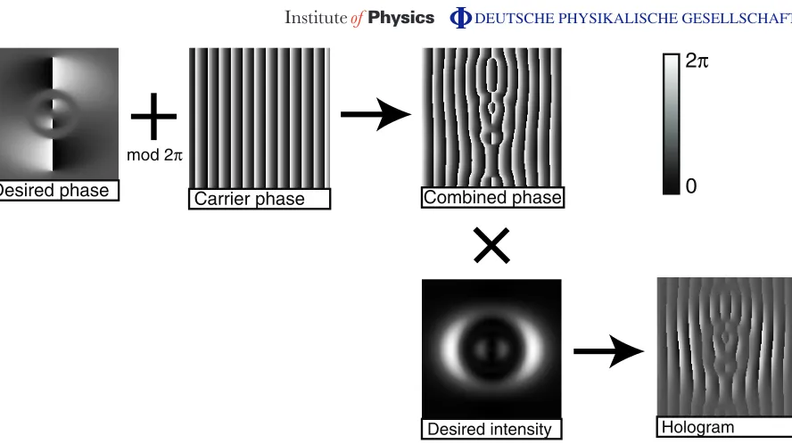
Figure 1. Illustration of the algorithm used to generate the holograms used in the link experiment (the knot hologram was similar). The desired phase of the beam at the beam waist is added mod 2πto a carrier. This is then multiplied by the desired intensity of the beam (corrected to account for the mapping of phase depth to diffraction efficiency) to produce the hologram which is used in the experiment. The 0–2πrange is represented in greyscale, as is actually programmed into the hologram.
ingredient modes are determined theoretically (as described above), the phase distribution of the link and knot beam in the waist plane,(x, y)beam =arg ψlink,knot(x, y,0),is calculated. To this
phase distribution is added the phase distribution of a blazed diffraction grating (x, )grating
(where is the period of the grating), such that the first-order diffracted energy is angularly separated from the other orders, which are subsequently blocked using a spatial filter. The desired intensity I(x, y) of the superposition is also calculated and normalized, such that the maximum intensity is unity. This intensity distribution is applied as a multiplicative mask to the phase distribution of the hologram, acting as a selective beam attenuator imposing the necessary intensity distribution on the first-order diffracted beam.
The resulting phase distribution of the hologram (x, y)holo, expressed within a 0 to 2π
range is given by
(x, y)holo =(((x, y)beam+(x, )grating)mod 2π−π)sinc2((1−I(x, y))π)+π. (4)
The sinc distortion of the intensity terms accounts for the mapping of phase depth to diffraction efficiency. An example of this process is shown in figure1.
SLM
Laser
Aperture
Mirror Volume where
[image:5.595.144.415.107.447.2]knotted/linked structures exist
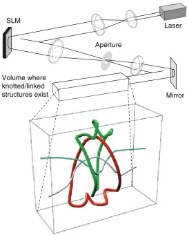
Figure 2. Experimental configuration used to produce the vortex beams. The expanded and collimated beam from a He–Ne laser is reflected by the spatial light modulator (SLM) displaying the required hologram. The beam is passed through a lens to spatially separate the diffraction orders. The first diffracted order is selected, and the other orders removed, by passing the light through an adjustable iris. A second lens is used to recollimate the beam and allow transverse cross sections of the beam to be imaged. A CCD camera is placed at different planes to record the intensity of the beam.
The optical beams were produced using a spatially filtered He–Ne laser, expanded to overfill the 20 mm aperture of the spatial light modulator, and configured to generate the appropriate superposition of Laguerre–Gaussian beams, as shown in figure2.
Theoretical simulation Experiment
1.00
0.00 Intensity
0.10
0.00 Intensity
0.01
0.00 Intensity
2π
0π Phase
[image:6.595.72.536.86.375.2]2R0 = 4w0
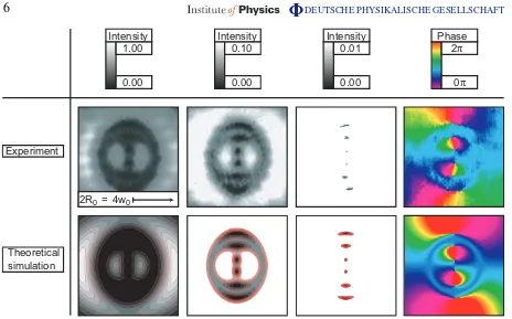
Figure 3. Experimental and theoretical representation of the transverse structure of the waist of the link field. A sequence of plots of intensity, with increasing degree of saturation, shows how the only structure measured are the vortex lines piercing the observation plane. The phase (conventionally represented using hue) shows the cyclic phase change around the vortices, establishing the singular phase nature of the intensity nodes.
on each side of the waist. Given that the fine details of the vortex threads lie in regions of near darkness and in order to measure the vortex positions within the beam cross section, it was necessary to over-saturate the CCD. The resulting image was mainly white, but contains points of darkness corresponding to the vortices as they intersected the plane of the CCD. A comparison of experimental and theoretical plots demonstrating the increasing saturation of the detector in the waist plane of the link field is shown in figure 3. Also shown here is the measured phase pattern of the beam, showing that the dark vortex threads are indeed singularities of the optical phase (this phase distribution was measured according to the methods described in [23]).
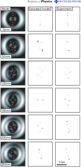
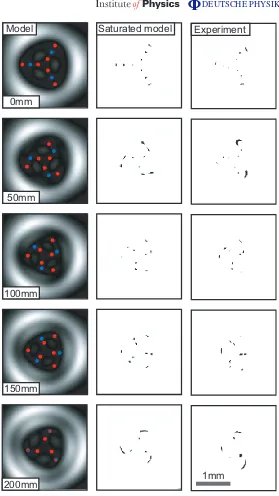
These transverse vortex coordinates were measured in neighbouring planes, enabling the three-dimensional spatial configuration to be deduced. The amplitude of the perturbation was chosen initially at the theoretically optimized value, then adjusted to give the best defined link or knot. In figures 4 and 5, images taken at various transverse planes through the vortex link and knot beams are shown alongside their simulated counterparts. The measured positions of the vortices are extremely close to those determined theoretically for the modelled beams.
Saturated model Experiment Model
250mm 150mm
200mm 0mm
50mm
100mm
[image:7.595.146.426.90.671.2]1mm
100mm
150mm
200mm 0mm
50mm
Model Saturated model Experiment
[image:8.595.146.425.91.587.2]1mm
Figure 5. Theoretical and experimental transverse cross sections of the vortex knot. The distances refer to the distance from the beam waist. In the model, the positions of the vortices are indicated by coloured spots, red (l=+1)and blue (l= −1). These vortices are observed as black dots in the saturated model and the experimental results.
a
b
c
[image:9.595.153.447.85.328.2]d
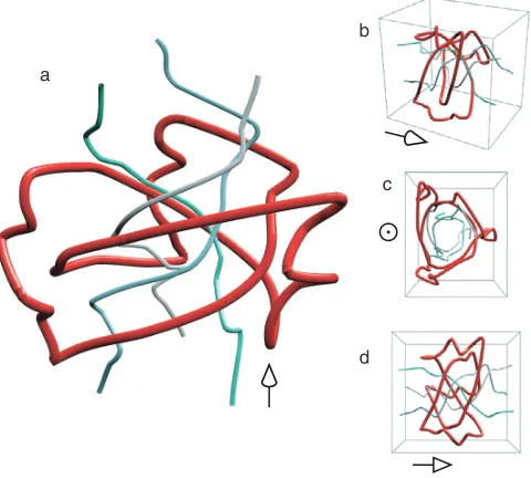
Figure 6. Three-dimensional representation of the experimental vortex link, reconstructed from the measured data. Different projections of the link are shown, and the direction of propagation in each case is indicated by the arrow. The link is formed by the red and green loops. The threading vortices, which do not take part in the link, are represented by thinner blue and grey lines. The scale for the direction of propagation has been reduced by approximately 1000.
a
b
c
d
[image:9.595.150.390.444.660.2]We have described the creation and observation of static knots and links of dark vortex threads in light waves, verifying an earlier prediction of Berry and Dennis that this was possible within optical wave fields. Knotted vortices have been studied theoretically since Lord Kelvin’s vortex atom hypothesis [24] in a range of different physical situations, such as hydrodynamics [25, 26], field theory [27] and nonlinear excitable media [28, 29]. However, in these contexts, nonlinearities mean that vortex knots are probably unstable. Our structures are superpositions of free space optical modes with the same frequency, so are temporally stable. It is not known theoretically whether arbitrary topological configurations of vortices can be embedded in free space optical fields; only a few special cases are known (the knots and links studied here [9,10], which have to be threaded, and certain braids [30], which require counterpropagating beams). In addition to being of fundamental interest, these experiments illustrate topological light shaping that might be used as a topological waveguide for quantum mechanical matter waves, such as Bose–Einstein condensates [31,32].
Acknowledgments
We are grateful to Michael Berry for useful suggestions and comments. Figures 6and 7were plotted in Mathematica using Mitch Berger’stubapackage. MRD acknowledges support from the Leverhulme Trust and the Royal Society. JC is supported by the Royal Society.
References
[1] Nye J F and Berry M V 1974 Dislocations in wave trainsProc. R. Soc. Lond.A336165–90
[2] Berry M V, Nye J F and Wright F J 1979 The elliptic umbilic diffraction catastrophePhil. Trans. R. Soc.A 291453–84
[3] Nye J F 1999Natural Focusing and Fine Structure of Light: Caustics and Wave Dislocations(Bristol: Institute of Physics Publishing)
[4] Bazhenov V Y, Vasnetsov M V and Soskin M S 1990 Laser beams with screw dislocations in their wavefronts
JETP Lett.52429–31
[5] Heckenberg N R, McDuff R, Smith C P and White A G 1992 Generation of optical-phase singularities by computer-generated hologramsOpt. Lett.17221–23
[6] Allen L, Beijersbergen M, Spreeuw R J C and Woerdman J P 1992 Orbital angular momentum of light and the transformation of Laguerre–Gaussian laser modesPhys. Rev.A458185–9
[7] Allen L, Padgett M J and Babiker M 1999 The orbital angular momentum of lightProg. Opt.39291–372 [8] Allen L, Barnett S M and Padgett M J (ed) 2003Optical Angular Momentum(Bristol: Institute of Physics
Publishing)
[9] Berry M V and Dennis M R 2001 Knotted and linked phase singularities in monochromatic wavesProc. R. Soc. Lond.A4572251–63
[10] Berry M V and Dennis M R 2001 Knotting and unknotting of phase singularities: Helmholtz waves, paraxial waves and waves in 2 + 1 dimensionsJ. Phys. A: Math. Gen.348877–88
[11] Leach J, Dennis M R, Courtial J and Padgett M J 2004 Knotted threads of darknessNature432165
[12] Rozas D, Law C T and Swartzlander G A 1997 Propagation dynamics of optical vorticesJ. Opt. Soc. Am.B 143054–65
[13] Berry M V 1998 Much ado about nothing: optical dislocation lines (phase singularities, zeros, vortices...),
Proc. Int. Conf. on Singular Optics, ed M S Soskin,SPIE34871–15
[15] Nye J F 2004 Local solutions for the interaction of wave dislocationsJ. Opt. A: Pure. Appl. Opt.6S251–4 [16] Dennis M R 2001 Topological singularities in wave fieldsPhD ThesisBristol University
[17] Durnin J, Miceli J J Jr and Eberly J H 1997 Diffraction-free beamsPhys. Rev. Lett.581499–501 [18] Adams C C 1994The Knot Book(New York: Freeman)
[19] Arlt J, Dholakia K, Allen L and Padgett M J 1998 The production of multiringed Laguerre–Gaussian modes by computer-generated hologramsJ. Mod. Opt.451231–7
[20] Vasara A, Turunen J and Friberg A T 1989 Realization of general nondiffracting beams with computer-generated hologramsJ. Opt. Soc. Am.A61748–54
[21] Basistiy I V, Slyusar V V, Soskin M S, Vasnetsov M V and Bekshaev A Y 2003 Manifestation of the rotational Doppler effect by use of an off-axis optical vortex beamOpt. Lett.281185–7
[22] Franke-Arnold S, Barnett S M, Yao E, Leach J, Courtial J and Padgett M J 2004 Uncertainty principle for angular position and angular momentumNew J. Phys.6103
[23] Leach J, Yao E and Padgett M J 2004 Observation of the vortex structure of a non-integer vortex beam
New J. Phys.671
[24] Lord Kelvin (W Thompson) 1867 On vortex atomsPhil. Mag.3415–24
[25] Moffatt H K 1969 The degree of knottedness of tangled vortex linesJ. Fluid Mech.35117–29 [26] Aref H and Zawadzki I 1991 Linking of vortex ringsNature35450–3
[27] Faddeev L and Niemi A J 1997 Stable knot-like structures in classical field theoryNature38758–61 [28] Winfree A T and Strogatz S H 1983 Singular filaments organize chemical waves in three dimensions. III.
Knotted wavesPhysicaD9333–45
[29] Sutcliffe P M and Winfree A T 2003 Stability of knots in excitable mediaPhys. Rev.E68016218 [30] Dennis M R 2003 Braided nodal lines in wave superpositionsNew J. Phys.5134
[31] Ruostekoski J and Anglin J R 2001 Creating vortex rings and three-dimensional skyrmions in Bose–Einstein condensatesPhys. Rev. Lett.863934–7