This is a repository copy of
Quantum-Classical Access Networks with Embedded Optical
Wireless Links
.
White Rose Research Online URL for this paper:
http://eprints.whiterose.ac.uk/106594/
Version: Accepted Version
Proceedings Paper:
Elmabrok, O and Razavi, M orcid.org/0000-0003-4172-2125 (2017) Quantum-Classical
Access Networks with Embedded Optical Wireless Links. In: 2016 IEEE Globecom
Workshops. 2016 IEEE Globecom Workshops (GC Wkshps), 04-08 Dec 2016,
Washington, DC, USA. IEEE . ISBN 978-1-5090-2482-7
https://doi.org/10.1109/GLOCOMW.2016.7849014
© 2016 IEEE. Personal use of this material is permitted. Permission from IEEE must be
obtained for all other uses, in any current or future media, including reprinting/republishing
this material for advertising or promotional purposes, creating new collective works, for
resale or redistribution to servers or lists, or reuse of any copyrighted component of this
work in other works.
[email protected] https://eprints.whiterose.ac.uk/
Reuse
Unless indicated otherwise, fulltext items are protected by copyright with all rights reserved. The copyright exception in section 29 of the Copyright, Designs and Patents Act 1988 allows the making of a single copy solely for the purpose of non-commercial research or private study within the limits of fair dealing. The publisher or other rights-holder may allow further reproduction and re-use of this version - refer to the White Rose Research Online record for this item. Where records identify the publisher as the copyright holder, users can verify any specific terms of use on the publisher’s website.
Takedown
If you consider content in White Rose Research Online to be in breach of UK law, please notify us by
Quantum-Classical Access Networks with
Embedded Optical Wireless Links
Osama Elmabrok and Mohsen Razavi
School of Electronic and Electrical Engineering University of Leeds
Leeds, LS2 9JT, UK
Email: [email protected] and [email protected]
Abstract—We examine the applicability of wireless indoor quantum key distribution (QKD) in hybrid quantum-classical networks. We propose practical configurations that would enable wireless access to such networks. The proposed scenarios would allow an indoor wireless user, equipped with a QKD-enabled mobile device, to communicate securely with a remote party on the other end of the access network. QKD signals, sent through wireless indoor channels, are combined with classical ones and sent over the same fiber link to the remote user. Dense wavelength-division multiplexing would enable the simultaneous transmission of quantum and classical signals over the same fiber. We consider the adverse effects of the background noise induced by Raman scattered light on the QKD receivers due to such an integration. In addition, we consider the loss and the background noise that arise from indoor environments. Decoy-state BB84 and measurement-device-independent protocols are employed for the secret key rate analysis.
Index Terms—Quantum key distribution (QKD), BB84, decoy states, measurement-device-independent QKD (MDI-QKD), op-tical wireless communications (OWC).
I. INTRODUCTION
Quantum key distribution (QKD) allows two distant users, Alice and Bob, to generate and share provably secure keys guaranteed by the laws of quantum physics [1]. Experiments have already shown the successful implementation of QKD over optical fiber and free-space [2], [3]. QKD has also been used for security assurance over core networks [4]–[6], in addition of being commercially available [7]. Despite such an outstanding progress, QKD has yet to offer more convenient access to its networks, via wirelessconnections, before being adopted by a large number of users. In our recent work [8], [9], we have investigated the feasibility of realizing wireless QKD in indoor environments. In this work, we extend our work by adopting wireless indoor QKD in more realistic scenarios. In particular, we look at different scenarios in which a wireless QKD link can be embedded into a hybrid quantum-classical access network. In such networks, quantum and classical signals are transmitted over the same fiber link. This poses a major challenge on the quantum channels due to the crosstalk noise induced by data channels mainly because of the Raman scattered light. In this paper, we propose three structures for wireless-enabled hybrid access networks and compare their performance in terms of the secret key generation rates that they can offer.
Embedding QKD capability onto mobile devices is consid-ered as an attractive solution for exchanging sensitive data in a safe and convenient manner, particularly in indoor environ-ments [10]. For instance, customers in a bank can exchange secret keys wirelessly with access points in the branch without waiting for a teller or a cash machine. However, the recipient may be located at a farther distance in some other scenarios, in which case networked connections are necessary. In the latter case, we can embed the wireless QKD link into a larger quantum-classical network. In this case, wireless QKD signals must somehow be collected and sent to the service provider over an optical fiber.
In order to have a cost effective solution, the collected wire-less QKD signals should possibly be transmitted along with classical signals over the same fiber links. A hybrid quantum-classical network would, however, face certain challenges due to the nonlinear effects in optical fiber, such as four-wave mixing and Raman scattering [11]. The latter is regarded as the dominant source of background noise in such a combination [11]. The impact of the Raman scattered light can be severe, because its spectrum can overlap with the frequency band of QKD channels, and, accordingly, it would increase the error probability at the QKD receivers. The impact of this noise can be mitigated [12]–[14], and even maximally reduced [16], but it cannot be fully suppressed. Our system would also confront another challenge due to the background noise and loss in indoor environments [8], [9].
In this paper, by considering the effect of various sources of noise mentioned above, three scenarios of embedding wireless indoor QKD links into quantum-classical access networks are investigated. In each case, we find the corresponding key generation rate for relevant QKD protocols. In particular, we use the decoy-state BB84 [17] and measurement-device-independent QKD (MDI-QKD) [18] protocols in our setups. The latter can provide a trust-free link between the wireless user and the central office in an access network. The price to pay, however, is the possible reduction in the rate.
II. SYSTEMDESCRIPTION
In this section, we describe the proposed setups for a hybrid quantum-classical network that includes an optical wireless QKD link. Such a link can wirelessly connect a mobile quantum user, in indoor environments, to the access network. We assume a total of N end users, which are connected to the central office via a dense wavelength-division multiplexing (DWDM) optical access network. The corresponding wave-lengths assigned to quantum and classical data channels are, respectively, denoted by Q={λq1,λq2, ...,λqN}, D = {λd1,
λd2, ...,λdN}. Userk = 1, . . . , N uses wavelength λqk (λdk) to communicate his quantum (classical) signals to the central office. The same wavelengths are also used for the downlink. In order to heuristically reduce the Raman noise effect, we assume that the lower wavelength grid is allocated to the QKD channels, while the upper grid is assigned to data channels [14].
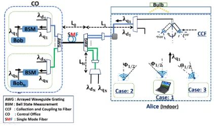
The end user is connected to the access network via a wireless link. Here, we focus on the quantum side of the story and investigate how such an end user can exchange a secret key with the central office. Three scenarios are proposed in this work. In the first scenario, see Fig. 1, the secret key exchange between Alice and Bob, at the central office, is accomplished in two steps using the decoy-state BB84 protocol. A secret key,K1, is generated between Alice and the Rx box in Fig. 1, and independently, another key,K2, is exchanged between Tx and the relevant Bob in the central office. The final secret key is then obtained by XORing K1 and K2. Note that, in this scenario, the two links are completely run separately, and, therefore, the wavelength used in the wireless link does not need to be the same as the wavelength used in the fiber link. In fact, for the wireless link, we use 880 nm range of wavelength, for which more efficient single-photon detectors are available. In the second and third scenarios, we use the MDI-QKD technique to directly interfere the quantum signal sent by the users with that of the central office. This can be accomplished by, if necessary, coupling the wireless signal into the fiber, and performing a Bell-state measurement (BSM) on the photons sent by Alice and Bob at either the user’s end (scenario 2), or the service provider’s end (scenario 3) as shown in Figs. 2 and 3. Scenarios 2 and 3 are of interest whenever the indoor environment we are working at is not trustworthy. For instance, if we are working at a public place, such as a coffee shop or an airport, we may not necessarily trust the owners of the local system. In such scenarios, MDI-QKD provides us with a solution to exchange a key with the service provider without trusting the local node. Scenario 1 is applicable whenever such a trust exists. For instance, in home networks, we can physically secure both Tx and Rx boxes, hence secure the data communication between them.
[image:3.612.337.541.50.171.2]We consider a particular indoor environment, in which it has been shown that wireless QKD is feasible [8], [9]. We consider a window-less room ofX×Y×Z dimensions, which is lit by an artificial light source. The possibly mobile QKD transmitter is placed on the floor and it transmits light toward
[image:3.612.330.545.254.374.2]Fig. 1. The first scenario, where secret key exchange between Alice and Bob is achieved in two steps.K1 is generated between Alice and Rx, whileK2 is generated between Tx and Bob. The resultant final key is computed by taking the XOR ofK1 andK2. Three cases are examined according to the position of the QKD transmitter, as well as the alignment and directionality of the light beam.
Fig. 2. The second scenario, where secret keys are exchanged between Alice and Bob using the MDI-QKD protocol. The BSM is performed at the user’s end in this scenario.
Fig. 3. The third scenario, where secret keys are exchanged between Alice and Bob using again the MDI-QKD protocol. The QKD signals are collected and coupled to the fiber and sent to Bob, where the BSM is performed.
[image:3.612.332.543.427.552.2]systems with minimal beam steering. In case 3, the light beam is narrowed and is directed toward the QKD receiver or the coupling element with semi-angle at half power of Θ1/2, so the system performance is improved. Note that in scenarios 2 and 3, we need to interfere a single-mode signal traveling in fiber with a photon that has traveled through the indoor channel. In order to satisfy the indistinguishibility criterion, we then need to collect only one spatial mode from the wireless channel as well. That would necessitate the use of some flexible beam steering for the telescope employed on the ceiling. Here, we assume that in all three cases such a telescope can be dynamically rotated to focus on the beam of light coming from the QKD source. In practice, one can alternatively use techniques reported in [15].
For our key-rate analysis, we need to estimate the loss and background noise within the wireless indoor environment, as well as through the optical fiber. With respect to the indoor environment, the background noise induced by the artificial lamp is calculated. The amount of background noise in the room depends on the power spectral density (PSD) of the employed light source. The receiver’s FOV is also important, since it limits the amount of background noise that may sneak into the QKD receiver. Here, we account for the reflected light from the walls and the floor that would be collected at the ceiling. We use OWC models for loss and background noise to calculate relevant parameters. In this paper, we follow the same methodology and assumptions, as presented in our recent work in [8], [9], to calculate the indoor channel transmittance,
H(0), and the corresponding background noise. For the sake of brevity, we do not repeat that analysis here. As for the optical link, we make the following assumptions. We consider a loss coefficient α in dB/km in the single-mode fiber. We also assume that the loss contributed by each multi-port (with more than two ports) DWDM multiplexer (labeled as AWG (Arrayed Waveguide Grating) in Figs. 1–3) is Λ in dB. We neglect the loss associated with two-to-one multiplexers. We have an additional coupling loss in scenarios 2 and 3 because we have to perform a BSM on photons traveling through different environments. In these scenarios, we assume that the wireless photon is coupled into a single-mode fiber, and will interfere with the photon sent by the central office in a fiber-based BSM module. In both scenarios, we consider a coupling loss ofξin dB. The implicit assumption here is that we collect only a single spatial mode of the wireless photon. In order to couple this photon efficiently to fiber then the effective FOV at the collection point should match the acceptance angle of a single-mode fiber. That requires us to use FOVs roughly below
6◦.
The main source of background noise on QKD channels in a fiber link is Raman scattering. The Raman noise generated by a strong classical signal spans over a wide range of frequencies, hence can populate the QKD receivers with unwanted signals [11]. Depending on the location of the QKD receiver, it may be affected by forward and backward scattered light [16]. For a classical signal with intensityI, at wavelengthλd, the Raman
noise power at a QKD receiver with bandwidth ∆λcentered
at wavelengthλq is given by [11] [12]
IRf(I, L, λd, λq) =Ie−αLLΓ(λd, λq)∆λ, (1)
for forward scattering, and
IRb(I, L, λd, λq) =I(1−e
−2αL)
2α Γ(λd, λq)∆λ, (2)
for backward scattering, where L is the fiber length, and
Γ(λd, λq)is the Raman cross section (per unit of fiber length
and bandwidth). The latter can be measured experimentally. We have used here the results reported in [11] for λd =
1550nm, and have used the prescription in [16] to adapt it to any other wavelengths in the C band. The transmitted power
I is also set to secure a BER of no more than 10−9 for all data channels.
III. KEYRATEANALYSIS
In this section, the secret key rate analysis for our proposed setups is presented considering non-idealities in the system. Without loss of generality, we only calculate the rate for user 1 assuming that polarization encoding is used. in practice, one can use time-bin or phase encoding techniques, which better suit our channel characteristics, and obtain similar results. The decoy-state BB84 protocol [17] is used for the first scenario, while the MDI-QKD protocol [18], [19] is employed for scenarios 2 and 3.
A. Scenario 1 with Decoy-State BB84 protocol
The decoy-state protocol enables weak coherent laser pulses to be used in QKD systems, while being robust against the photon-number-splitting attack [20]. The lower bound for the key generation rate, in the limit of an infinitely long key and infinitely many decoy states, is given by [17]
R≥q{−Qµf h(Eµ) +Q1[1−h(e1)]}, (3) whereqis the basis-sift factor, which is assumed to approach 1 in the efficient BB84 protocol [21] as employed in this work; the error correction inefficiency is denoted by f; and µ is the average number of photons per pulse for the signal state. Moreover, in (5),Qµ,Eµ,Q1,e1, and h(x)are, respectively, the overall gain, the quantum bit error rate (QBER), the single-photon gain, the error rate in single-single-photon states, and the Shannon binary entropy function, and they are given by [22]:
Qµ= 1−e−ηµ(1−nN)2, (4)
Eµ =
e0Qµ−(e0−ed)(1−e−ηµ)(1−nN)
Qµ
, (5) wheree0= 1/2 anded is the misalignment probability;
Q1=Y1µe−µ, (6)
e1=
e0Y1−(e0−ed)η(1−nN)
Y1
, (7) where
and
h(x) =−xlog2x−(1−x) log2(1−x). (9)
In the above equations, η and nN are, respectively, the
total system transmittance and the total noise per detector. As for nN, in the case of K1 in scenario 1, we assume that the background noise due to the artificial lighting source is denoted by nB1. The latter has been calculated using the
methodology proposed in [8]. As a result, the total noise per detector is nN = 12nB1ηd1 +ndc, where ηd1 is the detector
efficiency and ndc is the dark count rate per pulse for each
detector in the Rx box in Fig. 1. We neglect the impact of the ambient noise in our windowless room [8]. As forK2, the background noise is induced by the Raman scattered light. In this scenario, forward scattered light is generated because of the classical signals sent by the users, and backward scattered light is due to the signals sent by the central office. The total Raman noise power, at wavelength λq1, for forward and
backward scattering are, respectively, given by
ITf1= [IRf(I, L0+L1, λd1, λq1) +
N X
k=2
IRf(Ie−αLk
, L0, λdk, λq1)]10
−2Λ/10 (10)
and
ITb1= [IRb(I, L0+L1, λd1, λq1) +
N X
k=2
IRb(I, L0, λdk, λq1)]10
−2Λ/10, (11) whereL0is the total distance between the central office to the AWG box on the users’ end, andLk is the distance of thekth
user to the same AWG in the access network. In the above equations, we have neglected the out-of-band Raman noise that will be filtered by relevant multiplexers in our setup. The total background noise per detector, at the Bob’s end in Fig. 1, is then given by
nN =
ηd2λq1Td
2hc (I
f T1+I
b
T1) +ndc, (12)
whereηd2 is the detector efficiency at the Bob’s receiver,Td
is the time gate duration,his the Planck’s constant, and c is the speed of light in vacuum.
Similarly, in order to calculate the total transmissivity η, we use the following procedure. As for K1, η is given by
H(0)ηd1, whereH(0)is the path loss between Alice and Rx.
As for K2, η is given by ηchηd2, where ηch is the optical
fiber channel transmittance including the loss associated with AWGs, and it is given by 10−[α(L1+L0)+2Λ]/10
.
B. Scenarios 2 and 3 with MDI-QKD
The MDI-QKD protocol provides an efficient method of removing all detector side-channel attacks. This is done by performing the measurement by a third party, Charlie, who is not necessarily trusted. In this protocol, Charlie performs a BSM on Alice and Bob’s states prepared in X or Z
basis. Then, he announces the measurement outcomes of the
successful events over a public channel. Alice and Bob will also announce the bases used to encode the transmitted qubits. The rest of the protocol is similar to the BB84 protocol [23] in terms of sifting and privacy amplification procedures. We employ the MDI-QKD protocol [18] in scenarios 2 and 3.
In the limit of infinitely long keys, the key generation rate for an MDI-QKD protocol that uses ideal single-photon sources and the one that uses the decoy-state protocol are, respectively, lower bounded by
RMDI−QKD=Y11[1−h(e11:X)−f h(e11:Z)] (13) and
RMDI−QKD=Q11(1−h(e11;X))−f Qµν;Zh(Eµν;Z), (14) whereY11andQ11are, respectively, the yield and the gain of single-photon states given by [22]
Q11=µνe−µ−νY11, (15) whereµ(ν) is the mean number of photons in the signal state sent by Alice (Bob), and
Y11=(1−nN)2[ηaηb/2 + (2ηa+ 2ηb−3ηaηb)nN
+ 4(1−ηa)(1−ηb)n2N], (16)
where ηa and ηb are, respectively, the total transmittance
between Alice and Bob sides and that of Charlie and nN
represents the total noise per detector. In (13) and (14),e11;Z,
e11;X,Qµν;Z, andEµν;Z, respectively, represent the QBER in
theZ basis for photon states, the phase error for single-photon states, the overall gain, and the QBER in theZ-basis, and they are given by [22]:
e11;XY11=Y11/2−(0.5−ed)(1−nN)2ηaηb/2
e11;ZY11=Y11/2−(0.5−ed)(1−nN)2(1−2nN)ηaηb/2
Qµν;Z =QC+QE
Eµν;ZQµν;Z=edQc+ (1−ed)QE,
where
QC =2(1−nN)2e−µ
′
/2[1−(1−n
N)e−ηaµ/2] ×[1−(1−nN)e−ηbν/2]
QE= 2nN(1−nN)2e−µ
′
/2[I
0(2x)−(1−nN)e−µ
′
/2]
x=√ηaµηbν /2, µ
′
=ηaµ+ηbν, (17)
whereI0 is the modified Bessel function. In the above equa-tions,ed models possible errors due to polarization distortion,
which make the arriving photons distinguishable at the BSM module.
In the second and third scenarios, both Raman noise and indoor-channel background noise are present. The forward and backward scattered light is generated by the classical signals of users and the central office. The total Raman noise power, at wavelengthλq1, for forward, denoted byI
f
TABLE I
NOMINAL VALUES USED FOR OUR SYSTEM PARAMETERS.
Parameter Nominal value
Room size,X,Y,Z (4×4×3) m3
Φ1/2,Θ1/2 30◦,4◦
Average number of photons per signal pulse,µ=ν 0.5 Fiber attenuation coefficient,α 0.2 dB/km Loss due to each AWG (Λ), Coupling loss (ξ) 2 dB, 3 dB
Error correction inefficiency,f 1.16
Number of users,N 32
Dark count rate,ndc 10−7ns−1
Time gate duration,Td 100 ps
Misalignment probability,ed 0.033
Quantum efficiency,ηd1,ηd2 0.6, 0.3
denoted byIb
T3, scattering of scenario 3 are, respectively, given by ITf1 andIb
T1. For the second scenario, they are given by
ITf2= [IRf(I, L0+L1, λd1, λq1)
+e−αL1
N X
k=2
IRf(I, L0, λdk, λq1)]10−
2Λ/10 (18)
and
ITb2= [IRb(I, L0+L1, λd1, λq1)
+e−αL1
N X
k=2
IRb(Ie−αL
k
, L0, λdk, λq1)]10
−2Λ/10. (19) As a result, considering the background noise from the wire-less channel, the total noise per detector, nN, for scenario
s= 2,3 is given by
nN = 1
4
ηd2λq1Td
hc
IT sf +IT sb
+ηd2nB1ηcs
+ndc (20)
where ηc2 and ηc3 are, respectively, the loss in the
cou-pling element and the total loss that the indoor back-ground photons, generated by the bulb, will undergo before reaching the QKD receiver, and are given by 10−ξ/10 and
10−[α(L1+L0)+2Λ+ξ]/10
.
IV. NUMERICALRESULTS
In this section, we provide some numerical results for the secret key generation rates in the three proposed scenarios. We use a DWDM scheme with 100 GHz channel spacing in the C-band with 32 users. We defineQ={1530.8 nm, 1531.6 nm,...,1555.62 nm}andD={1560.4 nm, 1561.2 nm,...,1585.2 nm} for quantum and classical channels, respectively. We assume that λq1 is 1555.62 nm and the corresponding λd1 is
1585.2 nm. The classical data is transmitted with launch power
I = 10(−3.85+αL/10+2Λ/10)mW, which corresponds to a receiver sensitivity of -38.5 dBm guaranteeing a BER<10−9. In the three scenarios, we assume that L1 =L2=· · ·=LN
all equal to 500 m. We vary L0 to evaluate the rate versus distance behavior. The nominal parameter values used in our simulation are summarized in Table I.
In each scenario, three cases are considered for the light beam orientation of the QKD source. In the first case, the semi-angle at half power of the QKD source is Φ1/2 = 30◦,
10 20 30 40 50 60 70 80 90 100 10−10
10−8 10−6 10−4 10−2
Fiber length (km)
Secret
key
rate
per
pulse
Scenario:2 (MDI−QKD: Single−photon pulse) Scenario:3 (MDI−QKD: Single−photon pulse)
PSD=10−6W/nm Scenario:1 (Decoy−state BB84)
PSD=10−6W/nm
PSD=10−5
[image:6.612.48.298.75.188.2]W/nm
Fig. 4. Secret key generation rate versusL0+L1in case 1, when the QKD source is at the center of the room facing the QKD receiver, for scenarios 1 to 3.
10 20 30 40 50 60 70 80 90 100 10−10
10−8 10−6 10−4 10−2
Fiber length (km)
Secret
key
rate
per
pulse
Scenario:2 (MDI−QKD: Single−photon pulse) Scenario:3 (MDI−QKD: Single−photon pulse)
Scenario:1 (Decoy−state BB84)
PSD=10−7W /nm
Fig. 5. Secret key generation rate versusL0+L1in case 2, when the QKD source is at the corner of the room, but not fully aligned with the receiver, for scenarios 1 to 3.
and the QKD source is placed at the center of the room’s floor. With the same Φ1/2, the QKD source is moved to the corner of the room in the second case. We use Θ1/2 = 4◦ in the third case where the QKD source is located at the corner of the room as in the second case, but the beam in case 3 is directed and focused toward the QKD receiver or the collection element. A full alignment is assumed in the third case, while in the other two cases the QKD source is sending light upward toward the ceiling with a wider beam angle. We assume that at the receiver, the telescope is dynamically rotated to collect the maximum power from the user in the room. We assume that the effective receiver’s FOV would correspond to the acceptance angle of a single-mode fiber. Here, the QKD receiver’s FOV is assumed to be 6◦, which roughly corresponds to a numerical aperture around 0.1.
Figure 4 shows the secret key generation rate in case 1 for all three scenarios. In scenario 1, the key rate is given by the minimum of the key rates forK1 andK2. That is why it is constant up to a certain distance, at which point the rate for
[image:6.612.327.543.208.315.2]10 20 30 40 50 60 70 80 90 100 110 120 10−10
10−8 10−6 10−4 10−2
Fiber length (km)
Secret
key
rate
per
pulse
Scenario:2 (mdiQKD: Single−photon pulse) Scenario:2 (mdiQKD: Weak coherent pulse) Scenario:3 (mdiQKD: Single−photon pulse) Scenario:3 (mdiQKD: Weak coherent pulse) Scenario:1 (Decoy−state BB84)
[image:7.612.69.277.49.157.2]PSD=10−5 W /nm
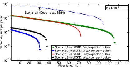
Fig. 6. Secret key generation rate versusL0+L1in case 3, with full beam alignment, for scenarios 1 to 3.
weak laser pulses. The same conclusion is held in case 2, as shown in Fig. 5, but, here, we even need lower PSD values on the order of10−7W/nm in order to achieve positive key rates. One may conclude that under the weak alignment conditions in cases 1 and 2, it may not be realistically practical to implement a trust-free wireless QKD access network.
The situation is, however, much more optimistic if full alignment between the wireless QKD receiver and transmitter is attained. Figure 6 compares the three scenarios in case 3 when such a full alignment is held. It can be seen that we can now achieve positive key rates in all three scenarios, even if we use the decoy-state protocol, with PSD values on the order of 10−5 W/nm, which correspond to white LED sources. It is interesting to note that the choice between the trust-free setups in scenarios 2 and 3 is driven by different factors. In Fig. 6, it can be seen that while scenario 2 has a better performance than scenario 3 for single-photon sources, the opposite is the case if weak laser pulses are used at the user’s source. This is associated with the relevance of the background noise generated by the bulb in the room. In scenario 2, this background noise will directly enter the BSM module, whereas, in scenario 3, it will be attenuated by the channel loss. It then turns out that for very low PSD values, scenario 2 offers a better performance than the setup in scenario 3. Once the PSD value grows, the opposite will be the case. This switching point happens earlier for the decoy-state system than the single-photon one, but it eventually happens for the latter as well. It can also be seen that all setups offer secure key exchange for up to tens of kilometers. This is compatible with the typical range of distance in many passive optical networks.
V. CONCLUSIONS
We proposed and studied three configurations that would enable wireless access to hybrid quantum-classical networks. All these setups would include an initial wireless indoor link that connects the quantum user to the network. Each user, in the access network, could also communicate classically with the central office via another wavelength in the same band. We considered setups in which a local relay point could be trusted, as well as scenarios that such a trust could not be held. We showed that, with proper beam alignment, it would be possible to achieve positive key rates in both cases in certain indoor
environments. The choice of the optimum setup would depend on various system parameters. Our analysis could identify the winner in realistic scenarios, where background noise from the environment as well as the Raman noise in fiber were both taken into account. This would enable high-rate wireless access to future quantum networks. This research is partly funded by the UK EPSRC Grant EP/M013472/1.
REFERENCES
[1] N. Gisin, G. Ribordy, W. Tittel, and H. Zbinden, “Quantum cryptography,” Rev. of Mod. Phys., vol. 74, pp. 146-195, 2002.
[2] B. Korzhet al., “Provably secure and practical quantum key distribution over 307 km of optical fibre,” Nature Photon., vol. 9, pp. 163-168, Feb. 2015.
[3] T. Schmitt-Manderbachet al., “Experimental demonstration of free-space decoy-state quantum key distribution over 144 km,” Phys. Rev. Lett., vol. 98, p. 010504, 2007.
[4] M. Peev et al., “The SECOQC quantum key distribution network in Vienna,” New J. Phys., vol. 11, p. 075001, 2009.
[5] M. Sasaki et al., “Field test of quantum key distribution in the Tokyo QKD Network,” Opt. Exp., vol. 19, no. 11, pp. 10387-10409, 2011. [6] F. X. Xu,et al., “Field experiment on a robust hierarchical metropolitan
quantum cryptography network,” Chinese Sci. Bull., vol. 54, p. 2991, 2009.
[7] See, e.g., http://www.idquantique.com/
[8] O. Elmabrok and M. Razavi, “Wireless quantum key distribution in indoor environments”, arXiv:1605.05092 [quant-ph].
[9] O. Elmabrok and M. Razavi, “Feasibility of wireless quantum key distribution in indoor environments,” 2015 IEEE Globecom Workshops (GC Wkshps), San Diego, CA, 2015, pp. 1-2.
[10] J. L. Duligallet al., “Low cost and compact quantum key distribution,” New J. Phys., vol. 8, p. 249, Oct. 2006; see also, arXiv:1608.07465. [11] P. Eraerds, N. Walenta, M. Legre, N. Gisin, and H. Zbinden., “Quantum
key distribution and 1 Gbps data encryption over a single fibre,” New J. of Phys., vol. 12, no. 6, p. 63027, 2010.
[12] K. Patelet al., “Coexistence of high-bit-rate quantum key distribution and data on optical fiber,” Phys. Rev. X, vol. 2, p. 041010, 2012. [13] K. Patelet al., “Quantum key distribution for 10 Gb/s dense wavelength
division multiplexing networks,” Appl. Phys. Lett., vol. 104, no. 5, p. 51123, 2014.
[14] S. Bahrani, M. Razavi, and J. A. Salehi, “Crosstalk reduction in hybrid quantum-classical networks,” to appear in Scientia Iranica, 2016. [15] A. Gomezet al., “Beyond 100-Gb/s indoor wide field-of-view optical
wireless communications,” IEEE Photon. Technol. Lett., vol. 27, p. 367, Feb. 2015.
[16] S. Bahrani, M. Razavi, and J. Salehi, “Orthogonal frequency division multiplexed quantum key distribution in the presence of Raman noise,” Proc. SPIE 9900, Quantum Optics, 99001C, 2016.
[17] X. Ma, B. Qi, Y. Zhao, and H.-K. Lo, “Practical decoy state for quantum key distribution,” Phys. Rev. A, vol. 72, p. 012326, 2005.
[18] H. K. Lo, M. Curty, and B. Qi, “Measurement-device-independent quantum key distribution,” Phys. Rev. Lett., vol. 108, p. 130503, 2012. [19] X. Ma and M. Razavi, “Alternative schemes for
measurement-device-independent quantum key distribution,” Phys. Rev. A, vol. 86, 062319, Dec. 2012.
[20] G. Brassard, N. L¨utkenhaus, T. Mor, and B. C. Sanders, “Limitations on practical quantum cryptography,” Phys. Rev. Lett., vol. 85, no. 6, p. 1330, 2000.
[21] H.-K. Lo, H.-F. Chau, and M. Ardehali, “Efficient quantum key distri-bution scheme and a proof of its unconditional security,” J. Cryptol., vol. 18, no. 2, pp. 133165, 2005.
[22] C. Panayi, M. Razavi, X. Ma, and N. L¨utkenhaus, “Memory-assisted measurement-device-independent quantum key distribution,” New J. Phys., vol. 16, p. 043005, Apr. 2014.