Theses Thesis/Dissertation Collections
6-1-2009
Testability of a swarm robot using a system of
systems approach and discrete event simulation
Matthew R. Hosking
Follow this and additional works at:http://scholarworks.rit.edu/theses
This Thesis is brought to you for free and open access by the Thesis/Dissertation Collections at RIT Scholar Works. It has been accepted for inclusion in Theses by an authorized administrator of RIT Scholar Works. For more information, please [email protected].
Recommended Citation
Using a System of Systems Approach
and Discrete Event Simulation
by
Matthew R. Hosking
A Thesis Submitted in Partial Fulfillment of the Requirements for the Degree of Master of Science
in Computer Engineering Supervised by
Associate Professor Dr. Ferat Sahin Department of Electrical Engineering
Kate Gleason College of Engineering Rochester Institute of Technology
Rochester, New York June 2009
Approved by:
Dr. Ferat Sahin, Associate Professor
Thesis Advisor, Department of Electrical Engineering
Dr. Shanchieh Jay Yang, Associate Professor
Committee Member, Department of Computer Engineering
Dr. Andreas Savakis, Professor and Department Head
Rochester Institute of Technology Kate Gleason College of Engineering
Title:
Testability of a Swarm Robot Using a System of Systems Approach and Discrete Event Simulation
I, Matthew R. Hosking, hereby grant permission to the Wallace Memorial Library to reproduce my thesis in whole or part.
Dedication
To my friends and family.
Of making many books there is no end,
and much study wearies the body.
Now all has been heard;
here is the conclusion of the matter:
Fear God and keep his commandments,
Acknowledgments
I am grateful for my advisor’s continual direction in completing this work as well as the friendship developed over the past year. I also appreciate my committee, Dr. Yang and Dr. Savakis, for their review and insights into this thesis. I acknowledge
my colleagues in the lab, Ryan and Eyup, for helping me and providing the opportunities to enjoy engineering together. Finally, I owe many thanks to my brothers, sisters, parents, friends, and family for remaining patient with my schedule
Abstract
Testability of a Swarm Robot Using a System of Systems Approach
and Discrete Event Simulation
Matthew R. Hosking
Supervising Professor: Dr. Ferat Sahin
Contents
Dedication . . . iv
Acknowledgments . . . v
Abstract . . . vi
Glossary . . . xiv
1 Introduction . . . 1
2 Background Review . . . 6
2.1 Cooperative Robotics . . . 6
2.2 Modeling and Simulation (M&S) . . . 10
2.2.1 Discrete Event System Specification (DEVS) . . . 12
2.2.2 DEVSJAVA . . . 15
2.3 System of Systems (SoS) . . . 16
2.3.1 Integration Property . . . 17
2.3.2 Interoperability Property . . . 18
2.4 Extensible Markup Language . . . 19
3 State of the Art Simulation Tools . . . 23
3.1 Simulators . . . 23
3.1.1 Robotics Simulators . . . 24
3.1.2 HIL Support. . . 25
3.2 SoS and DEVS Applied to Net-Centric Design . . . 27
3.2.1 DEVS/Service-oriented Architecture(SOA) . . . 28
3.2.2 DEVS/HLA . . . 28
3.3 Testing Methodology . . . 29
3.3.1 Formal Methods. . . 30
4 Discrete Event Based SoS Simulation Framework . . . 33
4.1 Initial Framework Support . . . 34
4.2 XML Architecture . . . 37
4.3 Interfacing Two Worlds. . . 40
4.3.1 Communication . . . 42
4.3.2 Synchronization . . . 43
4.4 Analysis of Systems . . . 43
4.4.1 Performance of A Single Robot . . . 44
4.4.2 Evaluating Emergent Behavior in SoS . . . 44
4.4.3 Measurement Methodology . . . 45
5 Robust Threat Detection Example. . . 46
5.1 Modeling the Other Systems . . . 47
5.1.1 Threat . . . 47
5.1.2 Radar Stations (Sensors) . . . 48
5.1.3 Command Center . . . 49
5.1.4 Virtual Environment . . . 50
5.2 Mobile Agent Model . . . 52
5.2.1 Communication Layer . . . 53
5.2.2 Control Layer (Synchronization) . . . 56
5.3 Simulations in Model Continuity Process . . . 60
5.3.1 Simulation Experiment . . . 61
5.3.2 Agent-in-the-Loop Simulation . . . 63
6 Testability Results & Discussion . . . 71
6.1 Aggregating Data for Analysis . . . 72
6.2 Measuring the Communication Statistics . . . 75
6.3 Measuring the Response to a Threat . . . 78
6.4 Measuring the Swarm Behavior . . . 80
6.5 Scalability . . . 84
7 Conclusion . . . 87
7.1 Summary . . . 87
7.2 Future Work . . . 89
7.2.1 AIL Framework . . . 89
7.2.2 Applications . . . 90
List of Tables
4.1 XML Tag Translation. . . 40
4.2 Summary of XML Identifiers . . . 41
List of Figures
2.1 A photo of assembled Groundscout . . . 8
2.2 Levels of Conceptual Interoperability Model (LCIM) . . . 20
3.1 Abstraction Layers in DEVS Net-centric Approach . . . 27
4.1 AIL Simulation Framework Abstraction View . . . 34
4.2 Correlation between an SoS and DEVS Models. . . 36
4.3 Interaction between atomic model and activity . . . 37
4.4 An XML based SoS architecture . . . 38
4.5 An XML based SoS architecture implementation . . . 40
4.6 Supervisor Functionality . . . 45
5.1 DEVS Phase Diagram of Threat Model . . . 48
5.2 Radar Station (Sensor) Model . . . 49
5.3 DEVS Block Diagram of Command Center Model . . . 50
5.4 DEVS Block Diagram of Virtual Environment Model . . . 51
5.5 DEVS model of gsRobot(Groundscout) . . . 53
5.6 Layers of AIL Communication Plug-in . . . 54
5.7 DEVS model of communication layer . . . 55
5.8 Data flow in DEVS Model . . . 57
5.9 DEVS model of control layer . . . 58
5.10 Threat Detection Control Unit. . . 59
5.11 Synchronization Control Unit . . . 60
5.12 Graphics used in virtual and AIL simulations . . . 61
5.13 Initial positions of agents in the SoS. . . 62
5.14 Scout helicopters intercept enemy tank . . . 62
5.15 Initial position of SoS (AIL Simulation) . . . 64
5.16 Real agent investigates threat (AIL Simulation) . . . 66
5.17 Virtual agent investigates threat (AIL Simulation) . . . 67
5.18 Groundscout in lab (AIL Simulation) . . . 68
5.19 Larger Swarm Cooperating (AIL Simulation) . . . 69
6.1 Analyzing the SoS: Input and Ouput Files . . . 73
6.2 Initial positions of robots in threat detection scenario . . . 75
6.3 Transmitted Packets Dropped per Minute . . . 77
6.4 Percentage of Dropped Transmitted Packets vs. Swarm Size . . . 78
6.5 Percentage of Successful Threat Investigations vs. Swarm Size . . . . 79
6.6 Average Response Time to Investigate a Threat . . . 80
6.7 Formation Violations per Minute vs. Swarm Size . . . 81
6.8 Formation Violations As Percentage of All Moves . . . 81
6.9 Average Distance between Robots during a Formation Violation . . . 82
6.10 Critical Violations per Minute vs. Swarm Size . . . 83
6.11 Critical Violations As Percentage of All Moves . . . 84
List of Listings
4.1 XmlStrEntity class declaration . . . 39
5.1 XML Message from Radar to Command Center . . . 65
5.2 XML Message from Command Center to Robots . . . 65
5.3 XML Message from Robot to Robot. . . 65
5.4 XML Message from Radar to Command Center . . . 67
Glossary
ACIMS Arizona Center for Integrated Modeling and Simulation.
AIL agent-in-the-loop.
AIS Artificial Immune System.
DDMS Department of Defense Discovery Metadata Specification.
DEVS Discrete Event System Specification.
DEVSJAVA A Java implementation of the DEVS formalism used as a simulator
for models. Developed by ACIMS.
DEVSML DEVS Modeling Language.
DoD Department of Defense (United States).
GIG Global Information Grid.
GPS Global Positioning System.
Groundscout A modular micro robot for swarm intelligence and cooperative
robotics research and applications. Developed by Dr. Ferat Sahin at RIT.
HIL hardware-in-the-loop.
IDE Integrated Development Environment.
IEEE Institute of Electrical and Electronics Engineers.
integration process of combining multiple entities to for a larger component.
interoperability a property referring to the ability of multiple entities to work
together to achieve a goal.
LCIM Levels of Conceptual Interoperability Model as proposed by Dr. Andreas Tolk.
liveness As presented by Dr. Winfield, a characteristic of swarm behavior in which
the swarm is exhibiting desirable behaviors.
MAC Medium Access Control.
model continuity a seamless migration from initial experimental simulations to
deployed systems in the field.
net-centric participating as a part of a continuously-evolving, complex community of
devices, information and services interconnected by a communications network.
PIC Programmable Intelligent Computer - a family of micro-computer chips devel-oped and manufactured by MicroChip, Inc.
RAM Random Access Memory.
RF Radio Frequency.
RIT Rochester Institute of Technology.
RS232 Recommended Standard 232 is an Electronic Industries Association standard
for asynchronous serial binary data signals.
RX abbreviation for “receive” in the communications field.
safety As presented by Dr. Winfield, a characteristic of swarm behavior in which
the swarm is not exhibiting undesirable behaviors.
SDK Software Development Kit.
SOA Service Oriented Architecture.
SoS Systems of Systems or System of Systems.
TCP/IP Transmission Control Protocol / Internet Protocol.
TDMA Time Division Multiple Access.
TX abbreviation for “transmit” in the communications field.
UAV Unmanned Aerial Vehicle.
XML Extensible Markup Language.
XPath XML Path Language.
Chapter 1
Introduction
Systems of systems (SoS) are comprised of systems which themselves are independent and complex systems that interact among each other to achieve a common goal. This goal requires a functionality greater than the functionality offered by any individual member of the SoS. For example, a Boeing 747 airplane is a system of an SoS, but an airport is an SoS. The goal of the airport is to check in passengers and luggage as well as provide security checks in addition to transporting them to another airport. The SoS concept is still in the developing stages and several formal definitions are available [1, 2]. For this work we considered the following definition: SoS are large-scale concurrent and distributed systems that are comprised of complex systems
working towards a larger, common goal. This is an information systems view as it
emphasizes the interoperability and integration properties of an SoS [3].
requirements. These stovepipe systems were created by vertical integration techniques which connected them functionally but without the flexibility of reuse or concern of future growth. This creates a barrier to data aggregation and meeting goals of the SoS as the systems cannot interact and communicate with new systems that become available unless those systems are coupled directly to the present ones. The sources of different data and the detriments to the interoperability requirements introduced by stovepipe systems are discussed in [4].
One solution to achieve interoperability is to standardize the communication medium among the systems. Interoperability is discussed in more detail in Section2.3
but conveys the ability of multiple systems to work seamlessly towards a goal. Two possible methods to standardize communication are [5]:
• Create a software model: each component in the SoS talks to the module embedded in itself
• Describe the data in a common language: each component in the SoS can understand and parse data from another system
data-driven approach avoids the risk of potentially large overhead and more readily supports legacy components which may not have a software model available [6]. A common understanding of the data exchanged among the members of the SoS can also be captured and processed later to determine the degree of success which the SoS completes its goal.
In a multi-agent system, the agents operate autonomously but it is important they cooperate with other agents to take better actions for the overall goal of the SoS. Interoperability in this work is achieved when each system exchanges data according to an XML standard commonly understood in the SoS. A system correctly communicates within the SoS if other systems can receive, parse, and interpret the transmitted data as the sender intended.
The integration property implies that systems can connect and interact with the SoS components regardless of their hardware and software characteristics, operating systems, and internal data format. Integration permits a dynamic SoS in which systems may join or leave the SoS at any time. Other systems need to be aware of this change to effectively and efficiently use the available resources in the SoS to meet the larger goal.
rebuilding a whole component. As the simulation model provides data increasingly close the observed implementation data, future test results can be expected with greater accuracy.
A seamless migration from initial experimental simulations to deployed systems in the field is referred to in general as model continuity. A simple four step process describing model continuity is found in [7]: conventional simulation, real-time simulation, hardware-in-the-loop (HIL) simulation, and implementation. A HIL simulation step allows part of the final system to be implemented and debugged before more resources are directed towards a flawed product.
The goal of this work is not to research new swarm intelligence algorithms but rather create a viable platform that is robust enough to aid in the development and testing of these algorithms and systems. AIL simulation also enables the examination of run time issues that may not be foreseeable in theoretical considerations.
This thesis has resulted in multiple conference publications: the initial XML com-munications framework [8], an extension to include hardware-in-the-loop simulation [9], and a more focused look on the framework along with initial results [10].
Chapter 2
Background Review
This chapter begins with an overview of cooperative robotics including the complexi-ties that arise from their control algorithms. Modeling and simulation is often used to examine and verify algorithms and is also studied in this chapter. Some focus is given to discrete event systems simulation and DEVSJAVA before discussing the growing field of Systems of Systems. Systems of systems is an approach to address the issues arising in large interconnected systems. The abilities of XML used in this work to aide in the simulation process ends the chapter.
2.1
Cooperative Robotics
Robots have become smaller and more cost effective over the past few years and are now being deployed in cooperative teams. A team may be homogeneous with multiple instances of the same robot or the team may be heterogeneous and made up of robots with different characteristics. Research into cooperative robotics requires multiple functioning robots. The research and development time to design and test a robot for production usually comes at a high price.
lower cost than proprietary ones, efforts have been documented which utilize lower cost, off the shelf components to create a community of robots [11]. There are also commercially available miniature robot platforms, such as the Khepera robot, used in swarm robotics research [12].
Another important aspect for a robotic platform used in cooperative research is the flexibility to be changed, updated, or expanded with new functionality. To this end, the Groundscout modular micro robotic platform was developed at RIT [13]. These robots place each functional resource on a different modular layer that connects to a common bus. The addition or removal of sensors involves connecting or disconnecting a layer from the robot. Ongoing research may require more or less functionality, but a new robot design can be avoided with this modular approach. Groundscout robots exhibit the following features: small footprint, differential drive mobility layer, wireless communication, ultrasonic sensors, infrared emitters and receivers, proximity sensors, GPS, and high level programming support.
A microprocessor and auxiliary PIC module for the wireless MAC protocol allow freedom in deploying control and communication algorithms to the platform. With cooperative robot teams, these algorithms must take into account the interaction and functionality of the group in addition to local navigation and task procedures.
Figure 2.1: A photo of assembled Groundscout
formations can vary as much as the imagination; a thorough overview of general considerations for formation control and different situations is presented in [14]. Graph theory is applied as an analysis tool create mathematical models and examine stability in groups [14,15]. The goal of any approach arises from the need to know a vital set of information: the positions of the robots.
specify the goal formation is discussed in [20] and uses a distributed algorithm. A second type of distributed control where no leader exists is referred to in literature as behavioral methods or emergent control. There exists early work with behavioral methods and examples of different techniques and static formations applied to autonomous vehicles for the military [21]. In a behavioral-based formation control each robot follows a set of rules, or behavioral constraints, related to its current role in the team. Flocking, schooling, and herds are all examples of emergent behavior in nature. In these situations, each member operates in an almost independent manner. The goal is achieved only when the team is viewed as a whole. Robot swarms designed to mimic this natural phenomenon have been shown to be successful in different applications. Ant colony swarm intelligence [22] and an artificial immune system (AIS) approach [23] have been applied to mine detection.
Swarm intelligence is well fitted to threat detection schemes or surveillance of an area. The robot teams have loose requirements for communication and cooperation while scanning for land mines, chemical spills, or any other disaster that is being monitored. When the threat or spill is detected and the robot team is also designed to contain the threat, cooperation shifts to a formation based control algorithm. Thus, as the robot team becomes more autonomous and robust in its actions and dynamic goals, the complexity increases and different control approaches may be more well suited than others for a given state of the system.
and evolving team goals is well suited to be better understood through simulation. Some robots may achieve increased performance by changing the control algorithm deployed. Much work has been done on control algorithms and it is important to have a suitable modeling and simulation framework to test the various approaches.
2.2
Modeling and Simulation (M&S)
Modeling a system entails describing a real system in some way as to generate data similar to the real world. Simulation is the process of executing the descriptions of the system to generate the data given some specific set of inputs. An experimental frame defines and bounds the set of inputs, or circumstances, for which the model is a valid representation of the real system. A computational approach to evaluating systems and models is provided as well. Theory of Modeling and Simulation, authored by Dr. Ziegler, is a classic text in this field [24]. The DEVS formalism invented by Ziegler, as well as a Java based simulator, are reviewed later in this section.
simulation environment.
The dynamic complexity present in cooperative robotics places additional value on using modeling and simulation practices to understand the system at hand and examine interactions that are not apparent before deployment.
Modeling and simulation can be used to understand the emergent behavior of an SoS if systems are modeled. Emergent behavior cannot be exactly predicted before run-time even if a single system operates with a known control algorithm. For example, one cannot predict the actions of an ant colony based on the understanding of individual ants. The behavior is affected by the environment and it is constantly evolving. Simulation can help explore the possible resulting behavior of an SoS or examine how that behavior may change if a new system or new capability is added to the existing SoS.
the next step in the development. System testing is accelerated with the ability to dynamically change the test input based on the current state. This attempt to break the system with more precise tests is not always possible in the physical deployment. The proposed work uses activities as part of a framework for flexible AIL simulation to support systems that do not have their own DEVS software. A data driven approach using XML reduces the need for detailed modeling of all components in a simulated SoS and enables easy integration and interoperability of heterogeneous systems.
2.2.1 Discrete Event System Specification (DEVS)
Discrete event system specification (DEVS) originated as a formalism for discrete event modeling and simulation but the methodology has grown to a wider use for systems theory within the research community [33]. It is a computational framework to support systems concepts and separates the model and the simulator. An abstract interface describes a model and a simulator and allows for different languages to implement them and provides for varying ways of simulating the model [34].
Event-driven models are an intuitive process humans use and understand. For example, a visitor arrives at your house and later leaves. A light bulb burns out and causes a replacement to be ordered and installed. These are all discrete events that cause a change in the current state of the system.
in a continuous domain can be simulated using event-driven methods, the complexity and overhead associated with this paradigm are generally more than a time-driven counterpart. However, if the simulation is time-driven and no state changes occur for extended periods of time, computing resources and execution time are wasted in evaluating each delta time period.
The event-driven paradigm and discrete event simulation method fit cooperative robotics system well, as much time could elapse between encountering obstacles, detecting a threat, or otherwise changing the behavior of the deployed team. The event driven architecture of DEVS enables the modeling of systems as naturally perceived by humans. This increases efficiency of simulating systems that may have extended time lapses between successive events as is sometimes the case in teams of robots working together to detect threats. A full explanation of modeling and simulation theory and the presentation of the DEVS formalism can be found in [24]. In DEVS, basic models, called atomic models, can be connected together to form larger, more complex models called coupled models. As stated for-mally using set theory notation, an atomic model in DEVS is a structure M =
X: is the set of input values
S: is a set of states
Y: is the set of output values
δint:S →S is the internal transition function
δext:Q×Xb →S is the external transition function, where Q={(s, e)|s∈S,0≤e ≤ta(s)} is total state set and e is the time elapsed since last transition
Xb denotes the collection of bags overX
(bags are sets in which some elements may occur more than once)
δcon :Q×Xb →S is the confluent transition function
(to resolve simultaneous internal and external events)
λ:S →Yb is the output function
ta:S →R0+,∞ is thetime advance function
Couplings among models are the connections which specify the relationships between
2.2.2 DEVSJAVA
There are a few software packages that implement the DEVS framework. JDEVS [35], OMNeT++ [36], ADEVS [37] are general simulation environments for various systems. DEVSJAVA is a Java based implementation of the DEVS formalism from the Arizona Center of Integrative Modeling & Simulation (ACIMS) co-directed by Dr. Zeigler [38].
The DEVSJAVA software supports and provides a portable framework to simulate models conforming to the DEVS formalism. DEVSJAVA enjoys widespread use across the research community from its robust modeling and simulating capabilities: understanding how children and humans reason [33], monitoring industrial steel production to lower costs [39], researching wild fire containment methods [40], and the cooperative robotics arena [3]. There is little to limit the use of DEVSJAVA as a general purpose simulation environment because of its generic implementation and support for additional extensions as needed.
DEVSJAVA supports a message passing communication scheme among the models in the system. Message passing is an intuitive architecture to facilitate couplings between models as well as modeling the peer to peer communication links within an SoS. Thus, XML data encapsulation can be implemented more readily using this existing message passing scheme.
change based on the external transition function, δext, or state changes can happen
internally according to the internal transition function δint and the time advance
function ta. It is possible that an external message arrives at the same time an internal transition is scheduled to occur. This conflict is resolved according to the confluent transition function δcon. Further implementation details of DEVS modeling
and simulation with Java is found in [38].
2.3
System of Systems (SoS)
Systems engineering is moving towards finding ways to make the sum of the parts greater than the whole. Systems can work together to share information, or specialized abilities, instead of repeating and duplicating capabilities in less efficient ways. Tasks are complex and span across disciplines and geographic area and it is too cumbersome to design a single system with the task of accomplishing the goal. Existing systems, or new systems, are made to work together to accomplish the goal instead of designing a new independent system.
Definitions of key terms for this field as used within U.S. Department of Defense (DoD) specifications follow.
System definition: a functionally, physically, and/or behaviorally related group of regularly interacting or interdependent elements; that group of elements forming a
unified whole [41].
SoS definition: a set or arrangement of systems that results when independent and
useful systems are integrated into a larger system that delivers unique capabilities [41].
integrating the capabilities of a mix of existing and new systems into an SoS capability
greater than the sum of the capabilities of the constituent parts [41].
The main goal of the SoS approach is to achieve greater performance from multiple systems and even find new capabilities not previously existing on any one system. There is a migration from end-to-end systems communication to global sharing of information among systems. Singular systems that have customized interfaces to other systems are no longer cost effective and flexible enough for the new net-centric infrastructure started by the growth of the Internet. The Global Information Grid (GIG) is the U.S. DoD’s concept for a unified communications framework among all systems across branches of the armed forces and intelligence communities [42, 43]. Net-centric design exposes the necessary interfaces for different systems to interact while maintaining a hidden view of the actual implementation technology. Network theories begin to play a greater role in understanding the interactions among the systems.
For this work we considered an SoS definition similar to the one presented: SoS are large-scale concurrent and distributed systems that are comprised of complex
systems working towards a larger, common goal. This is an information systems
view. An information system view focuses on the available data and it emphasizes the interoperability and integration properties of an SoS [3].
2.3.1 Integration Property
“Integration is the process of combining different components to form a subsystem or the integration of subsystems to a chain of systems, also known as system integration [45].”
Just as subsystems are integrated to form a single system, such as an automobile, multiple independent systems need to be integrated into a single SoS which provides functionality beyond that of any individual system. The discrete systems should work together for this new functionality despite hardware or software structures, operating systems, and internal implementation. Integration implies a connection to the system is possible, but it does not imply that the connection method is flexible to include future systems.
2.3.2 Interoperability Property
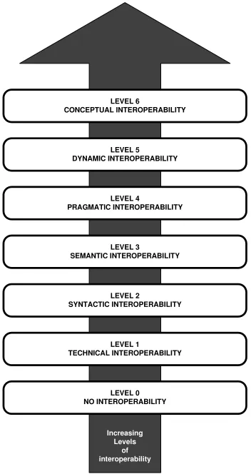
The base levels of interoperability in the Levels of Conceptual Interoperability Model (LCIM) [46] require data to be shared among systems in an unambiguous manner.
This technical interoperability is differentiated from the substantive interoperability
[47] required to achieve automated re-use of simulations over a network architecture. Interoperability is a term which is applied in varying degrees and is often left as an ambiguous statement. The LCIM attempts to clarify this broad and widely used term.
Composability is the highest abstraction of interoperability shown in Figure2.2. This figure is adapted from [49]. An explanation follows.
Interoperability at Level 1 is supported by the underlying technology standard used as a communication link between the systems. This channel, such as TCP/IP, enables the possibility of sending data. Level 2 syntactic interoperability defines a common data structure for the systems and is directly enabled through the use of XML to wrap data. If the meaning of XML tags are well defined, such as through XSL,
Level 3 semantic interoperability is also achieved. Level 4 pragmatic interoperability
defines and presents an interface of the model to other systems and Level 5 dynamic interoperability exists when systems can adapt to other systems entering and leaving the scope so that the available functionality evolves over time.
This work, an implemented framework for AIL testing, addresses the first three levels of LCIM for the systems in the simulation. The framework itself needs also to be interoperable with other systems and simulations as part of a larger M&S testing and verification methodology. Generic languages, such as XML, are often used to achieve interoperability at various levels of the LCIM.
2.4
Extensible Markup Language
LEVEL 6 CONCEPTUAL INTEROPERABILITY
LEVEL 5 DYNAMIC INTEROPERABILITY
LEVEL 4 PRAGMATIC INTEROPERABILITY
LEVEL 3 SEMANTIC INTEROPERABILITY
LEVEL 2 SYNTACTIC INTEROPERABILITY
LEVEL 1 TECHNICAL INTEROPERABILITY
LEVEL 0 NO INTEROPERABILITY
Increasing Levels
[image:37.612.222.398.89.421.2]of interoperability
Figure 2.2: Tolk’s Levels of Conceptual Interoperability Model (LCIM)
DEVS Modeling Language (DEVSML) [52] is built on XML to provide transparent simulator implementation. That is, a model is not restricted to a simulator based on the same programming language, but the model is described in a generic manner using XML which can be automatically implemented in the programming language of the available simulator.
SoS in this case, but must remember that it is discrete event based and the systems may not transmit data on a regular basis.
Parsing techniques for Java, as described in [53], summarize the different options for implementing the XML parser in the simulator. The Document Object Model (DOM) parsing technique will be used to efficiently have support for updating, adding, and removing information nodes. The XML document for the SoS will be changing as new data is received from components and the DOM is well suited for updating this changing information.
Extensible Stylesheet Language Transformations (XSLT)[54] assists parsers in understanding the meaning of each XML tag. Tags in XML are user defined unlike a markup language such as HTML where all tags are standardized and well defined. XLST is used to transform one XML document into another document. This document can be an XML file with different tags, or another type of document that is supported.
XML Path Language (XPath) is a query language used to find nodes in an XML document [55]. It allows easy navigation of the hierarchical tree structured nodes in the XML document. In simple terms, each level of the XML document defined by tags creates a node. XPath is a necessary component to successfully transform an XML document into another. An alternative method is to use code which traverses the DOM but this is a cumbersome procedure. Java 5 and later releases contain the
javax.xml.xpathpackage to provide a standard API to an XPath engine. Advanced
Chapter 3
State of the Art Simulation Tools
Robots were historically expensive and it was considered dangerous to deploy a field unit without careful verification of the control algorithm. Simulated environments have become more detailed and robots themselves more powerful over the years. Lower cost robots, such as Lego Mindstorm™, are available, but robotics research can also use more expensive systems; either choice may rely on simulation to verify algorithms.
Networks have also continued to expand and are prevalent in most systems. The current state of simulations over a network is also discussed. Testing methodologies, including rigorous formal methods and empirical observations, have increased in comprehensiveness but still remain largely customized for each application.
3.1
Simulators
3.1.1 Robotics Simulators
There exist robotic simulation platforms but they generally do not easily integrate or interoperate with other general systems. Webots™[56] provide the ability to interact with external controllers via TCP/IP. However, there is no guarantee to maintain consistent simulation steps across a larger network. Webots™ also does not support AIL simulation but jumps from simulation experiment to deployment.
As the robotics simulation field continued to mature and reach a wider audience there became open source collaborative simulation environments available. The Player Project [57] provides free software for robots including Stage, a 2D multi-robot simulator, and Gazebo, a 3D multi-robot simulator. Virtual models can be simulated, but references to migrating this control code to “hardware” are misleading. Player uses a client-server approach, where the client resides on the robot and interfaces with the actuators and sensors and provides a communication link back to the host computer which runs the control algorithm. Gazebo provides realistic feedback based on a physics engine but no real hardware is deployed.
Microsoft Robotics Studio provides a proprietary framework for simulating robots, their environment, and creating 3D visuals as well as remote operation over the web [58]. Using what the company calls Decentralized Software Services (DSS) and Concurrency and Coordination Runtime (CCR) it is possible for a simulation to span across a network. Robot control algorithms are deployable in autonomous hardware only if the robot is running a MS Windows based operating system and the studio software.
robotics simulators to researchers. However, to the systems designer, they fail to provide an effective way to implement AIL testing as part of the simulation to deployment transition.
Standalone, specialized simulation programs are no longer sufficient as we are now moving towards unified, distributed simulations of systems using web services and networks [59]. The systems we want to simulate now are increasingly complex, large scale, distributed systems. An SoS may be too large to practically simulate on a centralized computer system and need the computing power of a network. A distributed simulation inherently accounts for delays and transmission errors just as the deployed SoS may encounter. This locally distributed SoS simulation may then need to interoperate with other SoS simulations, or as the child of a parent who is part of a larger SoS. A simulation framework needs to be scalable and interoperate with systems across a network and share data among simulations in an SoS because an SoS is not limited to robotic systems.
3.1.2 HIL Support
existing systems in the SoS.
A thorough look at model continuity using discrete event simulation is found in [7]. The additions to the DEVSJAVA simulator infrastructure presented here are also fundamental to the AIL framework presented in this thesis. This work proposes the use of XML to encapsulate the data among systems and provides a method for including systems not running DEVSJAVA.
Early environments created to study a robot used overhead cameras and slow communication links to transfer virtual sensor data [60]. In [61], a special rig is built to perform HIL testing of an aerial vehicle’s sensors and flight algorithms without the need to fly the UAV. RAVE introduced a multi-robot simulator with support for real and virtual environments but no updated literature is found on the project [28].
A simulation based virtual environment to study cooperative robotics is discussed in [30] and robot-in-the-loop simulations are presented in [31]. An integrated test bed for robots utilizing an overhead camera system for monitoring the system is presented in [32]. In these frameworks, each robot is running a DEVS compliant simulator to create a distributed simulation. Synchronization is achieved at the DEVS simulator level and decisions can be made through knowledge of the global locations of each system.
3.2
SoS and DEVS Applied to Net-Centric Design
The U.S. military has been the biggest proponent for net-centric operations through-out its organization. The U.S. DoD believes sharing all information abthrough-out a situation with its individual forces will give greater awareness, increased effectiveness, and even fewer friendly casualties [63]. This all depends on the Global Information Grid (GIG) to provide a reliable net-centric environment through which data is shared. Fast testing and evaluation methods are required to make timely deployment possible [63]. As the GIG continues to realize an interconnected physical network an efficient means to test systems’ functionality on this new infrastructure is required. Figure3.1 shows an abstraction of the software layers in a DEVS net-centric framework to address this need.
MIDDLEWARE Net-centric Infrastructure
DEVS Modeling Language (DEVSML)
Atomic Models
DEVS Simulator
DEVS Simulator Coupled
Models
Language A Specific ML Language B Specific ML
. . .
. . .
[image:44.612.199.418.387.576.2]Real World Net-centric Applications
3.2.1 DEVS/Service-oriented Architecture(SOA)
Service-oriented architecture (SOA) is a collection of self-describing modules which can communicate with one another. From a programmers’s perspective, an ap-plication can be built from these modules by defining calls to their functions and subsequent transfers of data to other services. This promotes re-usability of existing technology while continually updating functionality with the addition of new services. Its framework can be used to create new systems and simulations. DEVS-based simulation web services using SOA in distributed simulations is presented in [64]. This approach adds a layer on top of the actual simulator but allows the user to create systems using models described in DEVSML from various web-enabled repositories using open standards. The additional layer allows greater automation to achieve interoperability across a network of computers to address the DoD’s systems level net-centric testing and evaluation goals.
3.2.2 DEVS/HLA
test organization responsible for certifying simulation systems as interoperable with existing and planned future net-centric operations of the DoD. RTSync [67], a commercial spin-off of ACIMS, is a corporation focused on providing professional M&S products for military and industrial applications using a DEVS/HLA framework.
3.3
Testing Methodology
The goal of modeling and simulating in this work is to test proposed systems’ and/or algorithms’ ability to meet the goals of the SoS. Automated methods of comparing results to the desired results is necessary in large and/or complex simulations. When the expected result is straightforward, comparing to a golden algorithm is possible. With emergent systems with diverse and dynamic goals and multiple solutions possible, analyzing the “success” of a system becomes more difficult. It is still possible to determine final outcomes, such as “Did the agent reach the destination in the allotted time frame?”, but more difficult to answer questions as “Did the systems work together in an efficient manner to disable the threat?” or “Under what circumstances will the system fail to achieve any further goals?”
3.3.1 Formal Methods
The field of cooperative systems and their formal analysis is still in infancy and no standard approaches have been developed. Ideally, systems’ interactions can be proven mathematically to give a desired outcome, or shed light on boundary conditions which should be considered when specifying a system’s ability. Some work has been done to provide formal verification methods of complex distributed systems; the subject has been approached by Winfield [68,69,70] for naive swarm algorithms but has not been applied to an SoS with heterogeneous and complex systems. There is a call for a more rigid design methodology for emergent systems and development of methodologies and practices for testing swarm systems.
Winfield’s approach discusses liveness, or exhibiting desirable behaviors, and
safety, not exhibiting undesirable behaviors [68]. The swarm behavior will not cease
3.3.2 Empirical Analysis
Empirical methods rely on testing as many different situations as possible and aggre-gating the results into a metric of performance or expected reliability. Documenting the experimental results of simulations is the most plausible method for analyzing an SoS simulation. The results have greater impact if the models closely match the real world systems.
The use of an overhead camera, or any similar setup, to synchronize systems or provide global state data for analysis is not always practical for a geographically distributed SoS. It may not even be an option if we are considering, for example, UAVs or an entire military division. Satellite could be available for large scale operations by the military. Aerial surveillance can provide higher resolution updates but this would be costly and still may not provide the desired frequency for covering the entire SoS picture.
Other means of analysis, such as tracking and aggregating interactions and communications from the other systems in the SoS, must be employed. In perhaps the most subjective example, human ‘systems’ provide the feedback for localized systems. A human’s complex judgment and perception abilities can be employed to determine whether the desired behavior was exhibited or if the swarm failed to meet the requirements. In addition to this metric of pass/fail given a certain experimental setup, data from other systems could be used to more objectively verify the agent in the loop.
Chapter 4
A DEVS Based SoS Simulation
Frame-work for Testing
The framework is presented in three conceptual areas: metadata and data require-ments, discrete event system specification, and the interface between real and virtual worlds. All steps of the model continuity method (simulation experiments, real time simulations, and agent-in-the-loop simulations) are supported, although the focus of this work will be on connecting the simulated world to the real system for AIL setups. The overview of this AIL simulation framework is contained in Figure 4.1 and shows the real world and virtual environment. They are connected through the agent model and a communications module. These modules each contain a driver to enable connections through the underlaying operating system and hardware devices. The agent model resides in a virtual environment which contains information about the location of all agents and obstacles and resembles the surroundings of the real system.
R
S
2
3
2
T
C
P
/I
P
.
.
.
Real World
AgentModel
Virtual Environment
[image:51.612.131.493.88.312.2]DEVS SoS
Simulator
Figure 4.1: AIL Simulation Framework Abstraction View
is provided by the underlying DEVSJAVA implementation which executes any model conforming to the DEVS formalism. An approach to interfacing and synchronizing real and virtual systems eliminates the requirement that all systems execute a common simulator or operating system. The interface between non-DEVS compliant robotic systems is abstracted to a software layer using activities to link with the hardware communication protocol of the robot. A prototype virtual environment and XML engine provide the conceptual proof of the viability of this approach.
4.1
Initial Framework Support
simulations is reduced, models and their relationships can be added and removed during runtime, and a generic interface declaration supports external Java Thread
execution.
The DEVS simulator interface allows the models to be executed in different ways.
A fast mode simulator executes the models for initial simulation experiments. The
simulation time advances as fast as the host can compute it. In contrast, a real time simulator synchronizes with wall time. Simulators are also categorized as
centralized or distributed. A distributed simulator coordinates time and messages
among simulators running on nodes connected by TCP/IP whereas a centralized simulator runs on a single workstation. These various simulators are used for the different stages of model continuity [7].
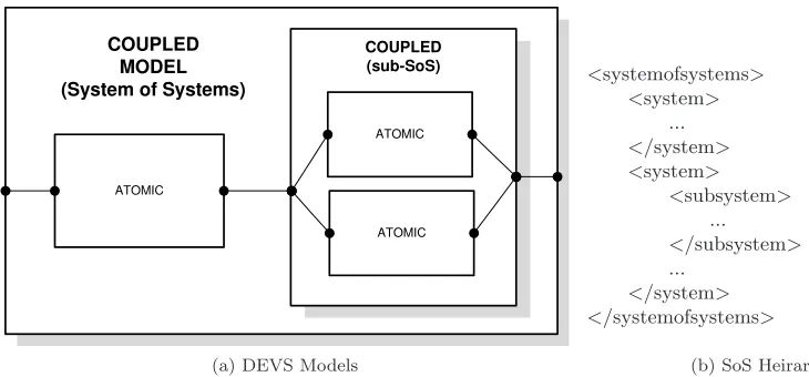
The system-subsystem hierarchical organizational view in a system of systems approach is intuitively supported by coupling DEVS atomic models. Figure 4.2maps an SoS hierarchy to DEVS models and demonstrates the organization of simulated models. At the topmost hierarchical level, the SoS is represented by a DEVS coupled model containing one or more instances of each of the models describing the independent systems. Each dot represents an input or output port where data enters or leaves the system. Figure4.2b lists the structure of the XML corresponding to this SoS. Communication links are implied by coupling the models together. The method
addCoupling(src,"portOut",dst,"portIn")
creates a directional communication channel from src’s portOut port to dst’s
ATOMIC
ATOMIC
ATOMIC COUPLED
MODEL (System of Systems)
COUPLED (sub-SoS)
(a) DEVS Models
<systemofsystems>
<system>
...
</system>
<system>
<subsystem>
...
</subsystem>
...
</system>
</systemofsystems>
[image:53.612.98.463.88.258.2](b) SoS Heirarchy
Figure 4.2: Correlation between an SoS and DEVS Models
added to a DEVSJAVA simulation and also removed by calling addModel(m) and
removeModel(m), respectively. These dynamic methods handle creating a new
simulator to bind to the model and updating all affected simulators when couplings are affected by changing models. Adding or removing models may also change the couplings. Couplings can be added or removed directly, as well. This may be the case when communication links among the models (systems) changes during the simulation as the result of some interaction or distance. A DEVSJAVA message, in basic structure, is one or more port-value pairs. A message which appears on a model’s outport is transferred to all inports connected by a coupling. A more generic class, entity, is used to provide a basic interface to most objects within DEVSJAVA. These objects, whether included in the DEVSJAVA library or user defined, are then compatible with DEVSJAVA storage containers and interfaces.
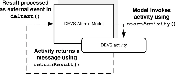
DEVS ActivityInterface provides an interface for external computations to
Threadanactivitycan complete any task independently of the simulator. “Results” of the task are returned to the model in a message via the interface’s methods. Figure 4.3 illustrates the sequence of interaction.
DEVS Atomic Model
Model invokes activity using
startActivity()
Activity returns a message using
returnResult()
Result processed as external event in
deltext()
DEVS activity
Figure 4.3: Interaction betweenatomicmodel andactivity
An activity can be used to drive a system actuator or receive signals from a sensor and create a message for the atomic control model if the system supports a DEVS simulator. A virtual model of this same sensor or actuator should have an interface similar to the real device. Adhering to this principle of model continuity, a common interface to a component in both real and virtual worlds, enables seamless migration from experiments to testing the new component in the field. abstractActivity
implements the same interface but runs as an atomic model, not a Thread, in the simulation. The ActivityInterface is used in this work to create communication drivers for any system to enter into the loop as well as interacting with the virtual world just as a system would in the physical realm.
4.2
XML Architecture
[image:54.612.170.452.168.289.2]<!–Created 11/8/2006 Author @Ferat Sahin–>
<?xml-stylesheet type=”text/css” href=”genericxml.css”?>
<systemofsystems>
<id>ID of the SoS</id>
<name>name of the SoS</name>
<system>
<id>ID of the first system</id>
<name>name of the first system</name>
<description>...</description>
<dataset>
<output>
<id>ID of the first output</id>
<data>Data of the first output</data>
</output>
<output>
<id>ID of the second output</id>
<data>Data of the second output</data>
</output>
</dataset>
<subsystem>
<id>ID of the subsystem of the 1stsystem</id>
<name>name of the subsystem</name>
<description>...</description>
<dataset>
<output>
<id>ID of the first output</id>
<data>Data of the output</data>
</output>
</dataset>
</subsystem>
</system>
</systemofsystems>
Figure 4.4: An XML based SoS architecture
Listing 4.1: XmlStrEntityclass declaration p u b l i c c l a s s XmlStrEntity e x t e n d s GenCol . e n t i t y {
p r o t e c t e d S t r i n g v a l u e ; . . .
}
defined its own set of tags, data exchange can occur, and the system can interoperate with the SoS. Extensible stylesheet language transformations (XSLT) would define a conversion method to adapt the data into the standard used by the larger SoS.
Within the DEVSJAVA software, XML string data is wrapped as XmlStrEntity
objects to inherit the properties of an entity. This allows the data to be sent as
messagesamong models in the simulation. XmlStrEntityalso provides basic parsing
<!–Created 12/01/2008 Author @ Matt Hosking–> <q>
<y>
<i>ID of the system</i> <s>
<i>ID of the first sensor</i> <d>sensor data</d> </s>
<s>
<i>ID of the second sensor</i> <d>sensor data</d>
</s> </y> <y>
<i>ID of the 2nd system</i> <s>
<i>ID of the sensor</i> <d>sensor data</d> </s>
</y> </q>
[image:57.612.226.394.346.477.2]Figure 4.5: An XML based SoS architecture implementation
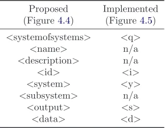
Table 4.1: XML Tag Translation
Proposed Implemented
(Figure4.4) (Figure4.5)
<systemofsystems> <q>
<name> n/a
<description> n/a
<id> <i>
<system> <y>
<subsystem> n/a
<output> <s>
<data> <d>
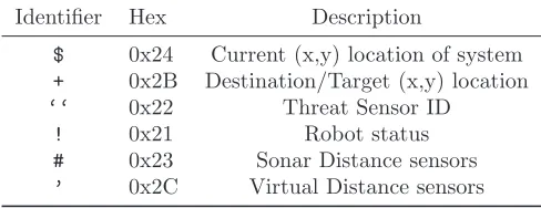
These include position and destination integer coordinates, threat detection status, ultrasonic distance sensors and corresponding “virtual distance” sensors.
4.3
Interfacing Two Worlds
Table 4.2: Summary of XML Identifiers
Identifier Hex Description
$ 0x24 Current (x,y) location of system + 0x2B Destination/Target (x,y) location
‘‘ 0x22 Threat Sensor ID
! 0x21 Robot status
# 0x23 Sonar Distance sensors
’ 0x2C Virtual Distance sensors
real agent is included in the simulation environment the real agent becomes another model from the simulated SoS’s point of view. The environment database and model representations of real systems works in conjunction with plug-in communication drivers to establish a connection and synchronize the state of the physical systems with the virtual SoS.
system sends is used to update its virtual representative model in the simulation. It is assumed the system has some type of communication, otherwise it would be very limited in its usefulness as part of an SoS. This framework for an AIL simulation supports various communication medium and standards using a plug-in approach.
Synchronization between the real system’s operation and the virtual agents in the SoS must also be considered. The virtual representation of the system in the simulation interacts with the virtual environment on behalf of the external system. This model representation, however, does not need to provide any control or implementation details of the system. The model, along with the communication plug-in, creates a means to transfer data back and forth between the simulation environment and the real world to both synchronize states and cooperate as an SoS.
4.3.1 Communication
4.3.2 Synchronization
The data communicated among the systems is used to synchronize the external agent with the SoS simulation. Synchronization is achieved when the virtual representation of the agent in the virtual environment accurately reflects the state of the agent in the physical world. It is the virtual representation which is used for generating sensor readings and location data related to the other simulated systems. For this reason, the virtual representation of an agent-in-the-loop also includes a “control” layer just as a virtual model does. This control layer, however, does not affect the behavior of the real agent. It interacts with the virtual environment based on the data made available to it by the communication layer. As coordinate data is received, for example, the synchronization control layer requests the virtual representative model be relocated within the virtual environment. This happens in much the same manner as a virtual system would initiate a move. The updated sensor data based on the inclusion of virtual objects can then be forwarded back to the external agent in a reverse process.
4.4
Analysis of Systems
4.4.1 Performance of A Single Robot
The performance of a robot is closely related to the technical specifications claimed by the unit. Position, heading, speed of travel, rate of communication, and accuracy of sensor readings can be measured very objectively. These factors may or may not affect the emergence of swarm behavior depending on the desired goal of the swarm and the algorithm deployed on the agents.
Convoy speed, number of adjustments, formation coherence, scalability, and sensitivity as performance metrics for the robot following convoy example in [29]. In the threat detection example of Chapter 5, there is no predefined formation to expect. Consistent communication, both a valid link and correct interpretation of data, is important for the system.
4.4.2 Evaluating Emergent Behavior in SoS
The desired swarm behavior of the mobile systems in the threat detection scenario is to converge on a given target location, yield to and hold the current position when encountering a teammate who is closer to the threat target, and return toward a home position when a threat no longer exists.
4.4.3 Measurement Methodology
Data is captured from each system as it becomes available to the SoS. This data is aggregated and recorded by a specialized command center, referred to in this work
as a supervisor, as a record of the data interactions in the SoS simulation. This
supervisor, depicted in Figure 4.6, compiles the data for comparison against a set of specified metrics. These metrics can be adapted as the SoS or experimental test requires. The results of this analysis, a summary of both desirable and undesirable events, are then presented to the user.
The scalability of the swarm SoS is viewed by comparing the supervisor’s summary across multiple runs with increasing numbers of agents. It is also possible, by comparing the same metrics, to evaluate different configurations of the SoS. Configurations involve the deployed locations of systems in the SoS but could also examine different systems’ ability to cooperate.
SUPERVISOR
Virtual Environment Data
Agents Command Center Requirements Testing Parameters M e a s u re m e n ts & T e s t R e s u lt s
Chapter 5
Robust Threat Detection Example
A robust threat detection scenario serves as the case study for the framework presented in this work. The scenario follows that of [8, 9, 62]. In this example there is a team of helicopters which can detect enemy tanks. The helicopters are dispatched by a command center to a location of the threat.
The helicopters are each stationed at a unique location in the map to provide a faster response time for detecting the enemy tank. It is expensive to continuously operate the team of scout helicopters. Sensors have been deployed in the area to create a sensor network to alert the presence of the tank.
a mobile robot on the ground is acceptable for testing.
Through this example application of the DEVS based AIL framework the work is shown to be a valid approach to simulation and analysis of SoS. The results of the threat detection simulation illustrate the behaviors of the components in the SoS and the successful communication using XML data messages. Next, we explore the individual components of the robust threat detection scenario. Then the simulations will be presented.
5.1
Modeling the Other Systems
The tank threat, radar station sensors, and command center are modeled in DEVS and together with the team of helicopters form the example threat detection SoS. The virtual environment model is also presented before focusing on the DEVS model for the robot. The control and names are specific to this example, but the general approach to modeling the Groundscout can be extended to any mobile system in order to be tested as an agent-in-the-loop using the DEVS based AIL simulation framework.
5.1.1 Threat
phase to move randomly as seen in Figure 5.1.
An arrow pointing to a rectangle signifies a message is created in the output function while in the given state. Inside the message rectangle the outport and specific object type of the message is listed in the form of outport : object type. A short description of the XML data contained in the message follows the arrow symbol (→). A number next to a dashed arrow is sigma, the time until the next internal event. Figure 5.1 shows the threat relocates every five time units using its internal transition function. A dark arrow from one state to another represents an external event transition. In the threat’s phase diagram, this arrows shows an XmlStrEntity
message object type on the startIn inport causing the event (inport : object type). Again, a description of the XML data in the message follows the arrow.
terrorizing init
Out : XmlStrEntity current location
5.0
startIn : XmlStrEntity
initial position of MobileThreat
Figure 5.1: DEVS Phase Diagram of Threat Model
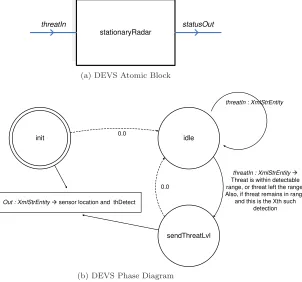
5.1.2 Radar Stations (Sensors)
threat remains within its range. The exact threat location cannot be determined by the sensor itself, so only the location of the station is sent to the command center. A block view and a phase diagram are shown in Figure 5.2.
stationaryRadar
statusOut threatIn
(a) DEVS Atomic Block
idle 0.0
sendThreatLvl
Out : XmlStrEntity sensor location and thDetect
0.0 init
threatIn : XmlStrEntity
Threat is within detectable range, or threat left the range. Also, if threat remains in range
and this is the Xth such detection
threatIn : XmlStrEntity
[image:66.612.184.486.173.455.2](b) DEVS Phase Diagram
Figure 5.2: Radar Station (Sensor) Model
5.1.3 Command Center
systems in the SoS, but each system decides what it will do with this information. The block diagram view of the model, in Figure 5.3, also shows aserialPortThread
contained in the command center. This is the thread responsible for handling operating system level calls to the serial port. Incoming and outgoing packets are each stored in a buffer monitored by the virtual robot model’s communication activity. The flow of data operates independently of the command center control logic; this is just an intuitive place to locate this part of the communications framework.
cmdOut sensorsIn txBuffer :: ArrayBlockingQueue
serialPortThread rxBuffer :: ArrayBlockingQueue
basicBaseStation
Figure 5.3: DEVS Block Diagram of Command Center Model
5.1.4 Virtual Environment
associated with the model and the spatial coordinator. The spatial coordinator does the computations necessary to update the internal database of locations and sensor readings of the system. After a time delay, emulating the time it would take the robot to move in the real world, the time coordinator notifies the spatial coordinator. At this point a message containing the new location and sensory data is sent back to the robot model.
.
.
.
Time Coordinator Spatial Coordinator Time Coordinator M o v e R e q u e s ts U p d a te d S e n s o r/ L o c a ti o n D a ta.
.
.
.
.
.
5.2
Mobile Agent Model
Swarm agents receive target coordinates from the command center and navigate autonomously from their current location to the destination. They communicate with one another to more efficiently use the resources in the SoS when going to a threat’s purported location. When no threat is present in the area, the swarm agents return to their respective home positions.
The AIL simulation framework’s interface to real agents is also presented here using the Groundscout robot as an example. This will highlight the structures and methodology to provide support for AIL simulation and testing of systems not executing a distributed DEVSJAVA simulator. The similar model design between a real and virtual agent reflects model continuity principles as well as the goal of testing swarm behavior of the robot. It is possible to add control to the virtual representation of a real agent to test the affects of deploying new functionality on the model.
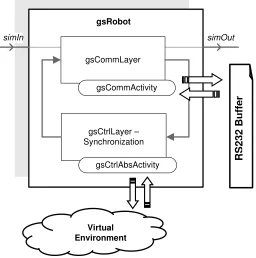
The DEVS model of a swarm agent is a coupled model as shown in Figure5.5. A coupled model allows the swarm agent model to more closely represent the hardware architecture of the Groundscout robot as it processes data. The Groundscout robot has separate control and communication modules which are modeled in the
communication and control layers. The layers work together to communicate and
synchronize the real robot with the virtual systems.
gsCommLayer gsCommActivity
gsCtrlLayer – Synchronization
gsCtrlAbsActivity
simOut simIn
gsRobot
Virtual Environment
R
S
2
3
2
B
u
ff
e
[image:70.612.185.441.250.508.2]r
Figure 5.5: DEVS model ofgsRobot(Groundscout)
5.2.1 Communication Layer
A hardware driver library containing aserialPortListenerinterface enables the operating system to interact with the underlying RS232 hardware. AserialPortThread
implements this interface and runs in the background to manage the RX and TX buffers. An activity associated with the communications layer model provides the backend DEVS support to the hardware driver’s buffers. The communications layer, an atomic DEVS model, implements the behavioral functions of the layer. The communications layer is explained from both a virtual system’s point of view and from the view of a model representing a real system. This highlights the similarities and differences between the models.
Robot Model (Coupled)
HARDWARE Hardware Driver (RXTX) Communications Module (DEVS Backend)
Simulated Model (DEVS)
serialPortThread :: Observable :: serialPortListener
RX Buffer TX Buffer
Communications Layer (Atomic) activity
Base Station
[image:71.612.153.465.326.572.2]Groundscout
Virtual System Model
A closer view of the communications layer is illustrated in Figure 5.7. There is an inport, rxMsg, and an outport, txMsg to facilitate communication with other systems in the simulation. The communication layer also must connect to the control layer in order to forward data to it and transmit any requested information to other systems. fromCtrlLayer and toCtrlLayer provide this path. The virtual systems’ communication layers contain an abstract activity (gsCommAbsActivity) associated with them to maintain the same control. A virtual system does not need access to any hardware devices; the abstract activity functions only as a place holder where the model representing a real system would use an activity (gsCommActivity).
gsCommLayer
txMsg
toCtrlLayer rxMsg
fromCtrlLayer
outputFromActivity
gsCommActivity
*txBuffer :: ArrayBlockingQueue
*rxBuffer :: ArrayBlockingQueue
Figure 5.7: DEVS model of communication layer
Real System Model
To facilitate the connection with the Groundscout robot the DEVS model includes
gsCommActivity. The activity previously illustrated in Figure 5.7 is now explained.
if the packet destination matches the model’s ID. It also places outbound data packets in the transmit buffer. The understanding of the data transfer enabled by the activity further emphasizes the data driven approach of describing the behavioral model of the robot.
The communication layer’s activity listens for updates to the incoming serial packet queue using the Java Observer-Observable API. The activity is an Observer to the
Observable serial port packet buffer accessed by the communication layer’s activity.
The data packets arrive as well-formed packets of bytes containing header information and a data envelope with XML encapsulated data. Then the activity extracts the XML messages from the packets and makes them available to the communication layer via the DEVS external transition function. The communication layer forwards the message to the control layer and/or broadcasts the message to other virtual systems. The control synchronization layer then makes a request to the virtual environment when a new location or sensor data from the real r