DESIGN AND TIMING ANALYSIS OF VARIABLE VALVE TIMING (VVT) FOR INTERNAL COMBUSTION ENGINE
MOHD EFENDI BIN HUSIN
This report are submitted to the Faculty of Mechanical Engineering As a partial to fulfill the requirement of
Bachelor of Mechanical Engineering (Automotive)
Faculty of Mechanical Engineering Universiti Teknikal Malaysia Melaka
ii
“I hereby to declare that the work is my own except for summaries and quotations which have been duly acknowledged “
Signature : ………
Author : MOHD EFENDI BIN HUSIN
iii
iv
ACKNOLEDGEMENT
Alhamdulillah, thanks to God because with His blessing, I can finish this project with successful. I would like to express my gratitude and appreciate to my PSM
supervisor, Mr. Herdy Rusnandi because he gives many valuable suggestion and advice throughout the project. He also help in obtaining the reference and read through the manuscript of this report.
Thanks should also to be forwarded to UTeM for their cooperation especially to staff and librarian because give support and provide facilities and references in
completing this research.
Also to take this opportunity to thanks my family and friends who have been my sides throughout this time for their moral support and loyalty. Thanks to you all.
v
ABSTRACT
vi
ABSTRAK
vii
TABLE OF CONTENT
CHAPTER CONTENT PAGE
DECLARATION ii
DEDICATION iii
ACKNOWLEDGEMENT iv
ABSTRAK v
ABSTRACK vi
TABLE OF CONTENT vii
LIST OF TABLE xi
LIST OF FIGURE xii
CHAPTER I INTRODUCTION
1.1 Project overview 3
1.2Problem statement 3
1.3 Objective 4
1.4 Project scope 4
CHAPTER II LITERATURE REVIEW
2.1 Introduction of VVT 5
2.2 The conventional valve timing 7
2.3 Categories of VVT 8
viii
CHAPTER CONTENT PAGE
2.3.2 Combined valve lift and phase
control (VLPC) 8
2.3.3 Variable event timing (VET) 9
2.4 Principles of current VVT 10
2.4.1 Axial movement of a piston with
helical gear teeth 11
2.4.2 Camshaft chain adjustment 11
2.4.3 Vane Type Systems 12
2.5 Advantages of VVT 13
2.6 Application of VVT 13
2.6.1 MIVEC by Mitsubishi 13
2.6.2 Valvetronic by BMW 15
2.6.3 VTEC by Honda 16
2.6.4 VVTL-i by Toyota 16
2.7 Mechanism of VVT 18
2.7.1 Rocker Arm 18
2.7.2 Camshaft 19
2.7.3 Poppet Valve 20
CHAPTER III METHODOLOGY
3.1 Introduction 21
3.2 Research on the problem involving
4G92 engine. 21
3.3 Analysis of engine system 23
3.3.1 Car specification 23
ix
CHAPTER CONTENT PAGE
3.4 Research on the problem involving
conventional 4G92 SOCH engine. 25
3.5 Research for VVT system 25
3.6 Research the potential VVT system 25 for existing engine
3.7 Design cam profile 25
3.7.1 Prescribed rocker arm motion 27
3.8 Conceptual Design 29
3.8.1 Example drawings with
Catia software 29
CHAPTER IV RESULT AND DISCUSSION 31
4.1 Introduction 31
4.2 Concept of VVT design 31
4.3 Timing analysis 32
4.3.1 Timing of opening and closing
exhaust valve 32
4.3.2 Timing of opening and closing
intake valve 34
4.3.2.1 Intake valve for
conventional timing 34 4.3.2.2 Engine speed at low RPM 38 4.3.2.3 Engine speed at high RPM 41 4.3.3 Comparison of conventional,
low speed and high speed RPM 44
4.4 Cam profile design 45
x
CHAPTER CONTENT PAGE
4.5Full design 49
CHAPTER V CONCLUSION AND RECOMMENDATION 51
5.1Conclusion 51
5.2 Recommendation 52
5.2.1 Fully variable valve timing
without camshaft 52
5.2.2 Variable Valve Event and Lift (VVEL) 53
REFERENCES BIBLIOGRAPHY APPENDICES
xi
LIST OF TABLE
NUMBER TITLE PAGE
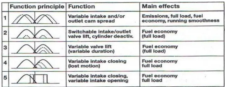
2.1 Basic function principle of variable valve 7 timing concept
3.1 Proton Wira Specification 23
3.2 4G92 SOCH Engine Specification 23
4.1 Exhaust valve displacement for conventional 32
4.2 Valve timing for conventional 34
4.3 Intake valve displacement for conventional engine 35
4.4 Valve timing at low engine speed 38
4.5 Intake valve displacement for low engine speed 39
4.6 Valve timing at high speed engine 41
xii
LIST OF FIGURES
NUMBER TITLE PAGE
2.1 VVT diagram 6
(Source: Ed. M, (2000))
2.2 Valve timing diagram 7
2.3 The inlet opening point for VPC 8
(Source: Garrett, T. K. (2001))
2.4 Stepped cams provide variable lift and 9
timing (VLTC) with rocker actuated valve (Source: Garrett, T. K. (2001))
2.5 Curves of variable event (VET) timing 10
without phase change
(Source: Garrett, T. K. (2001))
2.6 Helical spline system 11
(Source: Jost, K. (2002))
2.7 Camshaft chain adjuster 12
(Source: Jost, K. (2002))
2.8 Vane Type system 12
(Source: Jost, K. (2002))
2.9 Mivec mechanism 14
2.10 Vanos VVT mechanism 15
xiii
2.12 Rocker arm 18
2.13 Camshaft 19
2.14 Poppet valve 20
3.1 Flow chart project 22
3.2 Cam profile design – flat face follower. 29
3.3 Poppet valve 29
3.4 Rocker arm 30
3.5 Camshaft 30
4.1 Valve timing diagram for conventional engine 35 4.2 Timing diagram for conventional engine 37 4.3 Timing diagram at low engine speed 38
4.4 Timing diagram for low engine speed 40
4.5 Timing diagram at high engine speed 41
4.6 Timing diagram for high engine speed 44
4.7 Comparison between conventional,
low speed and high speed engine 45
4.8 Cam profile for low engine speed 47
4.9 Cam profile for high engine speed 48
4.10 The full mechanism of VVT 49
1
CHAPTER 1
INTRODUCTION
Nowadays, technology in automotive was blooming. Many automotive manufacturer produce may invention to conquer the market. These inventions are including producing the engine. Many consumer want cars with low capacity engine but have high performance and low fuel consumptions. As example, VVT (Variable Valve Timing) can give the small engine the high performance.
Variable valve timing is a system that allows for more efficient engine operation by varying the time at which valves opens, duration of opening, and valve overlap period. Some manufacturer called this mechanism in various name such as VVT-i, i-Vtec, Mivec, VTC, CVVT and others. Common camshaft was designed with the tolerance between low RPM for better fuel economy and high RPM for better performance.
2 For maximum engine performance at low engine speeds, the valves need to open longer and close differently than they do at higher engine speeds.
So, VVT engine have an ability to vary the valve timing and opening duration in both low and high speed operation. New technology such as i-Vtec mechanism allow camshaft to operate at best performance on any speed.
3
1.1 Project Overview
This project is about to design the new variable valve timing (VVT) system which wants to applied for internal combustion engine. The design must be suitable for spark ignition(S.I) engine.
To design this VVT, the mechanisms must be design first. To design this mechanism, all of aspect must be known to ensure mechanisms can be applied to the system.
Beside that to design this system, all the calculation for the mechanism must be calculate to get the theoretical result and the graphs.
1.2 Problem statement
In Malaysia, Proton Wira is the most seller car. It maybe this car is cheap and comfortable. But according to fuel consumption and power, it left out compare to other similar car because this car is using more fuel and its power is lower.
The factor of this problem is this car used regular engine with old technology. Now, almost of new car used the new technology such as turbocharged, VVT, hybrid and others. This technology will give the car’s engine more energy in performance and used low fuel consumption.
Now, Proton Wira must use the new engine to walk together with other cars. The engine must more powerful with low consumption like VVT system. VVT can be applied at Proton Wira engine because that engine is based on Mitsubishi engine (4G92). Now Mitsubishi have Mivec which is one of VVT type system.
4
1.3 Objective of Project
The main objective of this study is:
To design and timing analysis VVT mechanism for Spark Ignition Engine (SI engine).
1.4 Scope of Project
The scopes of this project generally involve the following: Analyze the valve timing
5
CHAPTER 2
LITERATURE REVIEW
2.1 Introduction of VVT
Variable valve timing (VVT) is a generic term for an automobile piston engine technology. VVT allows the lift or duration or timing of the intake or exhaust valves to be changed while the engine is in operation. Two-stroke engines use a power valve system to get similar results to VVT.
6
Figure 2.1: VVT diagram (Source: Ed. M, (2000))
At high engine speeds, an engine requires large amounts of air. However, the intake valves may close before all the air has been given a chance to flow in, reducing performance. On the other hand, if the cam keeps the valves open for longer periods of time, as with a racing cam, problems start to occur at the lower engine speeds. This will cause unburned fuel to exit the engine since the valves are still open. This leads to lower engine performance and increased emissions. Pressure to meet environmental goals and fuel efficiency standards is forcing car manufacturers to turn to VVT as a solution. Most simple VVT systems advance or retard the timing of the intake or exhaust valves. Others like Honda's VTEC switch between two sets of cam lobes at a certain engine RPM.
[image:19.612.159.518.538.677.2]7
TDC
BDC DC
00
1800
2700 900
160 ATDC
140 BTDC
580 ABDC
520 BBDC
Intake valve Intake
valve
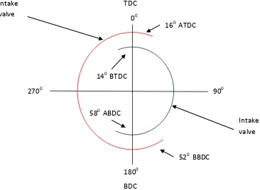
2.2 The conventional valve timing
[image:20.612.159.525.230.498.2]The valve timing for the conventional engine is fixed and not variable. It’s that means the valve timing is same when the engine run in low RPM and high RPM. For the 4G92 SOCH engine, the valve timing open 140 before top dead center (BTDC) and close at 580 after bottom dead center (ABDC). For the exhaust valve, it open at 520 before bottom dead center (BBDC) and close at 160 after top dead center (ATDC).
8
2.3 Categories of VVT
Variable valve timing (VVT) has three main categories. They are variable phase control (VPC), combined valve lift and phase control (VLPC), and variable event timing (VET) systems.
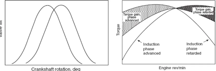
2.3.1 Variable phase control (VPC)
[image:21.612.105.540.290.434.2]Variable phase control, VPC implies varying the overlap so that low speed torque and, with it, specific fuel consumption is improved over most of the speed range. Since the duration of opening remains constant, wide-open throttle power is unaffected.
Figure 2.3: The inlet opening point for VPC. (Source: Garrett, T. K. (2001)) The inlet opening point can be retarded to reduce the overlap which, during idling, ensures stability and low emissions with VPC. For good low-speed torque and low fuel consumption, the inlet opening should be advanced, to increase the overlap.
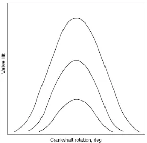
2.3.2 Combined valve lift and phase control (VLPC)
9 cam is extremely difficult to manufacture. Moreover, the axial loading introduced is about 10% of the force between the cam and follower, so a powerful controller is needed.
Figure 2.4: Stepped cams provide variable lift and timing (VLTC) with rocker actuated valves. (Source: Garrett, T. K. (2001))
From the figure above, at the lower lifts, friction is reduced, charge swirl enhanced and fuel consumption improved. The curves represent three steps, though up to ten are practicable
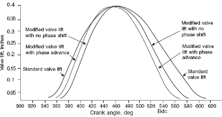
2.3.3 Variable event timing (VET)
10 that the ramps on the cam remain effective both as the valve begins to lift and when it re-seats.
Figure 2.5: Curves of variable event (VET) timing without phase change. (Source: Garrett, T. K. (2001)).
Valve lift remains constant and the variation is effected continuously. Part-load emissions and economy are improved, and the wide-open throttle condition is unimpaired
2.4 Principles of current VVT
11
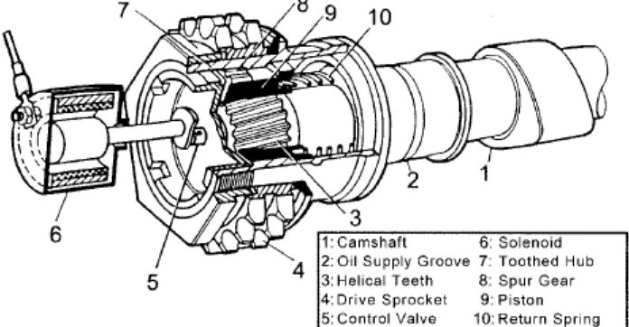
2.4.1 Axial movement of a piston with helical gear teeth
[image:24.612.151.499.239.420.2]The system is obtained from the functional principle of a spur/helical gear sleeve. When the engine was in idle mode, a return spring keeps the system safely in the first valve timing position. When engine oil pressure acts on the piston against the load exerted by the spring, the helical cut gear spline teeth will translate the axial displacement of the piston into a rotational movement. This causes rotation of the camshaft relative to the drive sprocket and thus relative to the crankshaft.
Figure 2.6: Helical spline system (Source: Jost, K. (2002))