mural
A Formal Development Support System
C. B. Jones
K. D. Jones
P. A. Lindsay
R. Moore
With contributions from J. Bicarregui, M. Elvang-Gøransson, R. E. Fields, R. Kneuper, B. Ritchie, A. C. Wills
printed: March 17, 2011 c
Contents
Foreword ix
Preface xi
1 General introduction 1
1.1 Formal methods 1
1.2 VDM development 4
1.3 TheIPSE 2.5 project 8
1.4 Proof assistant requirements 9
2 Introduction tomural 13
2.1 General introduction 13
2.2 The proof assistant 14
2.3 The VDM support tool 25
2.4 Reasoning about developments 27
3 Instantiation 33
3.1 Symbolic logic inmural 33
3.2 Classical first order predicate calculus 42
3.3 Some common data types 57
3.4 More complicated formulations 63
3.5 The theory of VDM 70
3.6 Some other logics 95
4 Foundation 107
4.1 Preamble 107
4.2 Syntax 108
4.3 Natural Deduction rules 119
4.4 Rule schemas and instantiation 125
4.5 Themural store 130
4.6 Syntactic contexts and well-formedness 134
4.7 Proofs 137
4.8 Morphisms 150
4.9 Pattern matching 155
4.10 Reading the full specification 163
vi Contents
5 The tactic language 171
5.1 Mechanising proof inmural 171
5.2 The language 172
5.3 The implementation of tactics 188
5.4 Examples 193
6 Implementing themural proof assistant 199
6.1 The process of implementation 201
6.2 The implementation 202
6.3 Lessons learnt and advice to the young 205
6.4 The future 208
6.5 The final word 209
7 Supporting formal software development 215
7.1 Abstract specification 215
7.2 Relating specifications 218
7.3 Support for reasoning about formal developments 219
8 Themural VDM Support Tool 221
8.1 Specifying VDM developments in VDM 221
8.2 Theories from specifications 230
8.3 Scope for growth 238
9 Foundations of specification animation 241
9.1 Approaches to animation 241
9.2 Denotational semantics of symbolic execution 245 9.3 Operational semantics of symbolic execution 249
9.4 Theories to support symbolic execution 257
9.5 Conclusions 261
10 Case Studies 263
10.1 Specifications in VDM 264
10.2 Transformation of VDM intomural-theories 264
10.3 A watchdog for a reactor system 267
10.4 An algorithm for topological sorting 281
10.5 Theories for VDM inmural 297
11 Conclusions 301
11.1 Experimental use ofmural 301
11.2 Detailed observations 302
11.3 Further developments 305
APPENDICES 308
A Summary of VDM Notation 309
B Glossary of terms 313
C The Specification of the Proof Assistant 319
C.1 The Raw Syntax 319
C.2 Subterm Access and Editing 327
C.3 Sequents and Rules 338
C.4 Instantiation and Pattern-matching 344
C.5 Signatures 349
C.6 Theories 357
C.7 Morphisms and Theory Morphisms 359
C.8 Proofs 368
C.9 The Store 395
D The specification of the animation tool 399
D.1 Data structure and some auxiliary functions 399
D.2 Operations 404
E The Theorem Prover’s House 411
Foreword
Programs and software constitute the most formal products known today since they must be processed by actual automata. Yet this software should solve problems in many areas, not all of which are supported by adequate scientific descriptions, let alone formalized ones. This major challenge of software design and engineering is often taken up in two phases which are logically distinct but can be carried out in parallel: in the first one, a clear and truthful formalization, viz. the ‘requirements specification’, of the problem at hand is built up; in the second one, a correct and efficient software system for the solution is designed on the basis of that formal specification. The first phase may well require the elaboration of adequate scientific models or theories, as close as possible to the semantic universe of the problems considered: bias towards specific solutions is thus usually minimized.
The present book focusses on the second phase, including the issue of correctness. The viewpoint it adopts is that the final programs are derived from the initial specifications through a design process which is decomposed systematically into manageable design steps. Each such step yields (on the basis of the previous version) a new intermediate formal version of the system under construction; the correctness of each new version is ensured by its correct derivation from, or by a verification against, the previous one. The composition of the records of the design steps serves as a record of the entire design process; the latter is correct providing each step and the overall composition are correct.
This viewpoint clearly restricts the scope of software design: the problem of building up an adequate problem description is played down; the design process is assumed to be decomposable into well-defined steps, each of which can be validated completely and on its own. These restrictive assumptions actually characterize ‘software design by formal methods’ which may use property-based formalisms, such as specific logics or abstract data types, or model-based formalisms such as function algebras, VDM, or Z. Significant industrial applications have been developed using such precise approaches.
x Foreword respect to a previous one is akin to proving a proposed conclusion can be derived from given assumptions; hence, the correctness of design steps may need the proof of theorems. Hand proofs of machine-generated texts risk becoming inhuman, or being boiled down to proofs by trust; it is thus tempting also to support precise design steps by computer. In fact, once computer aid enters the design process somewhere, it tends to propagate everywhere.
The problem is to ensure this computer ‘aid’ really aids: computers must serve minds, not conversely. Effective aid depends on the ease of using the notations associated with a given method, on the help provided in elaborating derivations and proofs, and on the speed. As a matter of fact, not many useful computer support systems are currently avail-able. Moreover, most assist designers in editing rather than in reasoning, and each gener-ally supports only one variant of one method; intellectual communication between related methods is thus handicapped.
The work reported in the present book aims at building and using a system which supports not only the strict verification of design steps, but also a reasonable range of for-mal methods. Indeed, design choices and correctness arguments are often similar across different methods. A generic system could in principle support complementary methods in different parts, for different levels, or at different times of the same design project; remember the mindpower required by industrial projects may exceed tens of mind/years. This aim of genericity is shared by related projects on ‘logical frameworks’ which es-sentially focus on theorem proving; little research on generic support systems is carried out for precise and scalable software design. The present book guides us in an unchar-tered ocean where navigation could become active and attractive. A much needed chart should indicate reasonable boundaries for the domains of human ideas and for the areas of mechanizable arguments.
The results reported herein must be seen as careful observations from a scientific ex-periment rather than as definitive, indisputable answers. They certainly provide valuable contributions in areas as varied as logical foundations, syntactical context-sensitivity, exe-cution of specifications as prototypes, interactive proof generation, organized composition of formal texts, efficient recording and accessing of such texts, pleasant mind-computer interface, support of specific methods and of specific system designs. Each of these issues deserves a book or a project of its own; many alternatives can be imagined at various lev-els. The originality and importance of the present work is in presenting an entire system approach which integrates all these aspects consistently and which already proves usable, albeit with some initial sweating.
A number of related systems are under experiment, for instance the generic logical frameworks for theorem proving. All experiments on such systems must benefit from one another, so that a gradual consensus emerges on the basis of the best technical character-istics. It is an essential merit of the present book to be indeed a remarkably substantial step in this crucial direction of scientific cooperation.
Preface
Formal methods bring mathematical precision to the development of computer systems. This book describes the outcome of a project which designed and built a support tool for formal methods such as VDM. The tool is known asmural and is so named because it was developed jointly by (the Computer Science department at) Manchester University and (the Software Engineering Division at SERC’s) Rutherford Appleton Laboratories. The major component ofmural is an interactive proof assistant; another component helps with the creation of formal specifications and designs. Work on the animation of specifications is also reported.
The so-called software crisis has been recognised for many years. Software develop-ment is claimed to be unpredictable and often results in products which are ‘bug ridden’. In fact there is no reason to confine the criticism to software: the task of developing any major digital system often appears to be beyond the methods employed by its developers. ‘Formal methods’ are seen as one way of bringing order and precision into the devel-opment of systems where errors cannot be accepted lightly. The importance of formal methods is becoming widely recognised. Brian Oakley, who was Director of the UK Alvey Programme, is quoted as saying:
. . . the main achievement of the Alvey Software Engineering Programme is the success with which ‘Formal Methods’ from the academic world have been pulled through to industrial use. The implications of this achievement are difficult to overestimate, for these Formal Methods are the route to much better software writing, and the economic consequences will be considerable – on a par with those of the revolution in civil engineering in the last century. The industrial relevance of one particular formal method, VDM, can be gauged from the series of CEC-funded international symposia [BJMN87, BJM88, BHL90].
The term ‘formal methods’ embraces the use of precise notation in specifications, and verification in design, of computer systems. Such precise specifications employ mathe-matical notation extended to make it easier to present specifications of computer-related concepts like programs. These extensions are given a precise semantics in terms of more basic mathematical concepts. Examples of such specification languages are ‘Meta-IV’ (the specification language of VDM) [BJ78, Jon80], ‘Z’ [Hay87, WL88, Spi89, MN89], ‘Larch’ [GHW85], COLD-K [Jon88], VVSL [Mid90] and RSL (the specification lan-guage of the RAISE project) [HH90]. Having a formally-based specification lanlan-guage makes it possible to convert the claim that an implementation (or even a design) satisfies a specification into the statement of a mathematical theorem. Proof of such a theorem establishes satisfaction for all cases. Examples of formal development methods with doc-umented proof obligations include VDM [BJ82, Jon80, Jon90c] and RAISE [BG90].
xii Preface managers and engineers because – in an industry as young as computing – few have been exposed to a systematic engineering approach to the design of computer systems. A major commitment to education is the only way to overcome this obstacle. The lack of standards is also a brake on the adoption of formal methods although work is now underway within both BSI and ISO towards a standard for VDM.
One of the consequences of the lack of standards has been the limited availability of support for formal methods. Of all of the supposed inhibitors to the wider use of formal methods, this is the most over-estimated! Although this book is about the provision of such support tools, it is worthwhile trying to identify the real needs if only to avoid the trap of assuming that the appearance of tools will, of itself, result in the widespread adoption of the methods which they support. Large specifications, such as [BBH+74, Ped87] have been handled with nothing more powerful than a text processing system. This historical fact is not to be seen as an argumentforunder-provision. In fact, relatively simple parsers and type checkers (e.g. ‘SpecBox’ [BFM89] for VDM or ‘fuzz’ for Z) certainly detect many simple errors in specifications. Furthermore, they help minimize the dangers of what is undoubtedly the most difficult task with formal specifications: errors are far more likely to creep in during changes to a specification than during its initial creation. A system to support formal methods must therefore provide tools to enter and type check specifications.
Millennia of mathematics, and even a century of formal logic, show that proofs can be constructed with pencil and paper. Given today’s technology, it is not difficult to become more productive at a full-screen editor, if only because of the ability to insert lines in proofs. This is especially true of so-called ‘natural deduction’ proofs because of the way they grow from the outside boxes to fill in the internal lines. Providing it is done conscientiously, theprocess of constructing even an outline proof should detect most errors in the statement of a supposed theorem because of the way it cross-checks the original claim (an obvious example is the way that, in proving that the body of a loop preserves an invariant, the invariant provides a sideways look at the purpose of the loop; such an alternative point of view is likely to uncover any error in coding the body).
But the formal development of computer systems can involve large specifications and many proofs of considerable size. In business environments, requirements are likely to change part way through development (cf. [Leh89]). Appropriate support tools can greatly improve the productivity of engineers who are employing formal methods. The project which is reported in this book addressed the provision of such tools.
This book has been produced by revising a collection of the papers which were written during the project. They have been edited to make a more coherent text and material has also been specifically written for this book. In some places, this gives rise to repetition; this has been left in the hope that the reader can read separate chapters independently of one another. A good overview of the work can be obtained by reading Chapters 1–3, 6, 7 and 11. Chapters 1 and 2 are introductory. The main component of themural system is a proof assistant – this is described in detail Chapters 3 to 6 of this book; Chapters 7 and 8 describe the work on a VDM support tool (VST); and Chapter 9 describes a novel approach to the animation of specifications. Chapters 10 and 11 are again relevant to all components ofmural: the former describes some applications and the latter draws some conclusions and sets out further research goals.
The mural system is available for both research and commercial use; it is written in Smalltalk’80 and requires a large workstation to run. Details of how to obtainmural are available from Dr. Richard Moore, PEVE Group, Department of Computer Science, Manchester University, M13 9PL, U.K. In addition to this book, an introductory video and a ‘User Guide’ are available.
The specific contributions to this book are given in the following table. In addition, the four main authors took responsibility for editing the whole work and all authors read other parts of the book in various drafts.
Preface C. B. Jones Chapter 1 C. B. Jones Chapter 2 R. Moore Chapter 3 P. A. Lindsay Chapter 4 P. A. Lindsay Chapter 5 R. E. Fields Chapter 6 K. D. Jones
Chapter 7 J. Bicarregui and B. Ritchie Chapter 8 J. Bicarregui and B. Ritchie Chapter 9 R. Kneuper
Chapter 10 M. Elvang and R. E. Fields Chapter 11 C. B. Jones
Appendix A C. B. Jones Appendix B omnes
Appendix C P. A. Lindsay and R. Moore Appendix D R. Kneuper
Appendix E A. C. Wills
Acknowledgements
We should like to express our gratitude to John Fitzgerald, who contributed to the instan-tiation of themural proof assistant and who also provided many valuable comments on the various drafts of this book. Thanks are also due to Lockwood Morris, a senior visiting fellow involved with the project for one year, who contributed to the development of the proof model (‘boxes-and-lines’) for an early prototype ofmural, and to Michel Sintzoff, who provided invaluable external criticism of our evolving ideas.
We are grateful to SERC and the Alvey Directorate for providing funding for the IPSE 2.5 project. In addition, CBJ would like to thank SERC for support under the Se-nior Fellowship Grant and the Wolfson Foundation for its grant, and MEG acknowledges partial support of a grant from the Danish Technical Research Council (STVF).
Chapter 1
General introduction
This chapter describes the context in which the scientific work reported in later chapters was undertaken. After a general description of formal methods, VDM is used as an ex-ample to make the sort of tasks involved in formal development more precise. Section 1.3 outlines the overall project in which the work on formal methods was undertaken. The last section in this chapter deduces a number of requirements for the support of the theorem proving process. Chapter 2 offers an introduction to themural system itself.
1.1
Formal methods
Before focusing on formal methods for the development of computer systems, it is worth looking at what the adjective ‘formal’ indicates when applied to notations and proofs. To be called formal, a notation must have some understood meaning or semantics. For example, in the logic of propositions, the expressionA∧(B∨C)depends in a precise way on what the identifiersAetc. denote. Exactly how such meaning can be defined need not be discussed here. The important fact is that a claim that the expressionsA∧(B∨C)and
A∧B∨A∧Chave the same meaning is, in any given logic, either true or false.1 Unlike in what computer scientists call ‘natural languages’, expressions in a formal language have a formal semantics which can settle disputes about their intended interpretation.
One might then expect that a formal specification language for computer systems should be such that the precise meaning of any particular specification can only be dis-puted through ignorance. This expectation can be fulfilled. But, without the additional bonus of being able to reason about such specifications, the cost of their construction might be hard to justify. Fortunately, formal specification languages, at least for sequen-tial computer systems, are also tractable in the same way as logic notation: proofs can be constructed.
The essence of what makes a proof formal is that its steps rely only on symbol ma-nipulation. Consider the claim made above about the two propositional expressions. One half of what needs to be proved is that the second expression can be deduced from the first. This can be written as a sequentA∧(B∨C) ` A∧B∨A∧C. One rule of deduc-tion about∧is that from a conjunction either of its conjuncts can be deduced. Thus both
A∧(B∨C)`AandA∧(B∨C)`B∨Care valid steps in a proof. An entire proof of the required result can be built from such simple steps. More remarkably, any true statement
1Of course, in classical logic it is true; as it is in VDM’s LPF – see below; but the symbols like∧could
in propositional logic can be proved using a small repertoire of basic rules.
Rather than imbed proofs in text, it is possible to make them more readable by dis-playing them. In the style known as ‘natural deduction’ the required proof is
fromA∧(B∨C)
1 A ∧-E(h)
2 B∨C ∧-E(h)
3 fromB
3.1 A∧B ∧-I(1,h3)
inferA∧B∨A∧C ∨-I(3.1) 4 fromC
4.1 A∧C ∧-I(1,h4)
inferA∧B∨A∧C ∨-I(4.1) inferA∧B∨A∧C ∨-E(2,3,4)
Proof that and distributes over or (one direction)
In this proof, steps 1 and 2 are shown as being justified by a rule known as ‘and elimina-tion’ (∧-E). It can be expressed by a deduction rule
∧-E E1∧E2
Ei 1≤i≤2
Such rules are really schema for an infinite set of possible deductions. If known (proven) expressions can be found to match the hypotheses above the line, then a conclusion which matches what is written below the line is valid. The matching process in this instance linksE1withAandE2withB∨C. Thus line 2 of the proof is justified by eliminating the left conjunct from the overall hypothesis of the proof.
A more interesting rule is that which facilitates the elimination of disjunctions. This can be thought of as providing a way of reasoning by cases. The rule is
∨-E E1∨E2; E1 ` E; E2 ` E
E
The final conclusion of the boxed proof above uses this rule withE1substituted byB,E2
byC, andE byA∧B∨A∧C. Notice here that, as well as an expression B∨Cwhich is needed as a hypothesis, two subsidiary proofs are required. To apply the or-elimination rule, the facts thatB ` A∧B∨A∧C andC ` A∧B∨A∧Care required. In the given proof, these are shown by the inner boxes 3 and 4. The required proofs for these two boxes are easy to complete. Step 3.1 follows from the hypothesis of box 3 and the already proven line 1 by the and-introduction rule (∧-I).
∧-I E1; E2
E1∧E2
The conclusion of box 3 follows from the rule of or-introduction
∨-I Ei
E1∨E2 1≤i≤2
1.1 Formal methods 3 can be completely checked by symbol manipulation. There is no room for debate about whether a formal proof does or does not follow the rules.
In passing, it is also worth mentioning that the steps of such a proof can be understood either forwards from the hypotheses to the conclusion or backwards from the goal to sub-goals. In fact, it is frequently useful to attempt both directions when trying to discover a proof. It is explained below that the freedom to work in any order was a major design goal of themural proof assistant.
Having established a benchmark of ‘formality’, the topic of formal methods can be explored more carefully. It is claimed above – and the claim is illustrated in the next sec-tion – that specificasec-tion languages exist which deserve the adjective ‘formal’. Is it then possible to prove that a program satisfies a specification? Under certain assumptions the answer is yes. The programming language itself can be regarded as a formal language be-cause it has a precise semantics. In an ideal world, this semantics is given by something like the definition of ALGOL 60 in [BJ82]; at the other extreme it can be given by the code of the compiler. In practice, neither of these texts would be usable in a proof and what is needed is a series of proof rules for program constructs which are designed in the same spirit as those for logics. The strongest assumption then – under which programs are proven to satisfy a specification – is that the implementation (compiler2and machine) re-flect the proof rules used in such proofs. There is also an assumption of practicability: the size of programs for whichpost factoproof is practical is severely limited. Methods like VDM respond to this observation by offering ways of decomposing a design into stages which can be separately justified. This has the additional advantage that errors made early in design are detected long before running code is created. In traditional software devel-opment, such errors might well be detected only when the code is available for testing. Since ‘scrap and rework’ is a major cause of lost time in software development, carefully applied formal methods such as VDM can actually improve the productivity of the devel-opment process. One further caveat about proving facts about programs is in order: what is (theoretically) possible is to show that one formal text – the program – satisfies another – the specification; this can neverprovethat the specification describes the system desired by some user.
There are, within the formal approach to system development, three more-or-less dis-tinct3paradigms; implementations can be developed by:
• iterative specification, design, and verification; • program transformation; or
• constructive mathematics.
VDM [Jon90c] is taken as the principal example of the first paradigm in this book. The early Floyd/King style of verification condition generation leads to proof obliga-tions called ‘verification condiobliga-tions’. These are, however, open to the criticism [Cra85] – when appliedpost-facto– that it is often hard to relate the verification conditions to the program. Methods of ‘data reification’ and ‘operation decomposition’ in VDM provide
2The unavoidable reliance on a compiler is the reason that so much of the early work on formalization
focussed on defining programming languages – see [McC66, JL71, Jon79b].
3Of course these paradigms overlap, and it could be argued that the first and the third are different
many instances of proof obligations which are made intelligible to the user by having the steps of development convey the structure of the correctness argument.
The ‘program transformation’ approach is typified by CIP [CIP85, B+87]. The basic idea is to transform inefficient – but clearly correct – ‘implementations’ into runnable programs. A transition from recursive functions to iterative procedures is an example of such transformations. But many transformations have associated applicability conditions which give rise to proof obligations when used.
The most direct use of formal reasoning is in the ‘constructive mathematics’ paradigm. Specifications are recast as statements that an implementation exists; and a ‘program’ is extracted directly from a constructive proof of the claim. NuPRL [C+86] is an example of a system supporting this paradigm.
1.2
VDM development
In order to provide more specific examples of the sort of proofs which are required in the formal development of software, an outline of parts of VDM is given. Appendix A provides a glossary to VDM notation. For a fuller, and more pedagogic description of VDM the reader is referred to [Jon90c].
1.2.1
Specification
A VDM specification describes the behaviour of a system in terms of the operations which can be performed by the system. The meaning of these operations is specified by pre- and post-conditions. Pre-conditions describe under what circumstances the system is required to perform and post-conditions describe what function is to be performed. In very simple systems, it is sometimes possible to describe the behaviour by considering only inputs and outputs; most interesting systems also have a state which reflects the effect of ear-lier operations. In VDM, pre-conditions define which input and initial state combinations must be handled by an operation while post-conditions relate inputs and initial states to outputs and final states. In general, post-conditions are shorter than constructive algo-rithms to achieve the desired result. Moreover, the use of abstract objects makes even more dramatic abbreviation possible by allowing a specification to be written in terms of objects which match the application rather than the intricacies of the final implementation machine.
The notion of state is then central to a specification in VDM. If one were to be de-scribing a system4 which handled a collection of signals (Sig is the name of the set of these objects), one might define the (abstract) state (Abs) as
Abs :: poss : Sig-set
curr : Sig-set inv(mk-Abs(p,c))4c⊆p
Here the sets of possible (poss) and current (curr) signals are stored as fields of the composite object Abs; furthermore, the data type invariant constrains any valid object
mk-Abs(p,c)∈Absto have itscset contained in itspset.
As has been claimed, VDM offers a formal language (sometimes known – in order to distinguish it from the method – as ‘Meta-IV’): its expressions can be expanded into
1.2 VDM development 5 standard mathematical ones. It is convenient here to present a partial expansion since this is necessary to present specifications to themural system. The stateAbscan then be defined viaAbs0 as follows
Abs0 :: poss : Sig-set
curr : Sig-set
Abs={a∈Abs0|inv-Abs(a)}
inv-Abs:Abs0→B
inv-Abs(a) 4 curr(a)⊆poss(a)
For most systems that are specified in VDM, there are many operations affecting the same state. These operations represent the external interface of the system. They are gathered together with the state into a module. The state itself is considered to be hid-den within the module and can only be manipulated by the operations. Here, only one operation is given. Furthermore, in order to minimize the discussion of VDM’s module construct, its specification is given in a way which ignores some of the sophistication of VDM.5 An operation (ADD) which adds a new signal to the field curr within the state could be specified
ADD(new:Sig) ext wra : Abs
prenew∈poss(a)
postcurr(a) =curr((a−)∪ {new} ∧poss(a) =poss((−a)
The post-condition relates the fields of the initial state(−a to those of the final statea; the pre-condition invites the developer to ignore cases where thenewsignal is not in theposs
field of the initial state (ahere).
Paradoxically, one test of a specification language is whether it can be used to write nonsense! VDM’s pre- and post-conditions can be used to specify operations which can-not be built. But one can make mathematically precise the claim that this has can-not hap-pened. An operation issatisfiableif for any possible starting condition (as given by the pre-condition) there is a possible state and result which satisfies the post-condition. For the current example, this can be written in the predicate calculus as
∀new∈Sig, (−a ∈Abs·
pre-ADD(new, (−a) ⇒ ∃a∈Abs·post-ADD(new, (−a,a)
This is the first example of a proof obligation from VDM. Its proof is straightforward and is not pursued here but it is worth noticing the way in which the data type invariant (inv-Abs) expands for the differing quantifiers
5TheADDoperation could be specified as follows
ADD(new:Sig) ext rdposs:Sig-set,
wrcurr:Sig-set prenew∈poss
∀new∈Sig, (a−∈Abs0·
inv-Abs((−a)∧pre-ADD(new, (a−) ⇒
∃a∈Abs0·inv-Abs(a)∧post-ADD(new, (a−,a) Satisfiability proof obligations are a check on the internal consistency of a specification. For complex systems, a user might use the mural proof assistant to provide proofs for those proof obligations which are automatically generated by the VST. Another sort of proof which might be undertaken before the process of design begins is to prove properties about combinations of operations. This can, to some extent, ameliorate doubts as to whether the formal specification does describe a system whose behaviour will be accepted by users. Chapter 9 of this book describes an alternative approach to the animation of specifications.
1.2.2
Reification
Development in VDM proceeds by data reification (making more concrete) and/or opera-tion decomposiopera-tion. In order to illustrate the sort of proof obligaopera-tion which arises during developments, a simple step of reification of theAbsstate is considered. Thepossset is represented by a sequence (without duplicates)posl; the currset is represented by a list
curl, of the same length as posl, which contains Boolean values – atrue value in curl
indicates that the corresponding element ofposlis considered to be in the set6
Rep0 :: posl : Sig∗ curl : B∗
Rep={r∈Rep0|inv-Rep(r)}
inv-Rep:Rep0→B
inv-Rep(r) 4 lenposl(r) =lencurl(r)∧is-uniquel(posl(r))
is-uniquel:X∗→B
is-uniquel(l) 4 ∀i,j∈indsl·i6=j ⇒ l(i)6=l(j)
In VDM, the precise relationship between Abs and Rep is normally7 documented by a ‘retrieve function’ which maps elements of the latter to elements of the former. For the simple example in hand this is
retr-Abs:Rep→Abs retr-Abs(r) 4
mk-Abs0(elemsposl(r),{posl(r)(i)|i∈indsposl(r)∧curl(r)(i)})
6Again VDM offers the more compact notation
Rep :: posl:Sig∗ curl:B∗
inv(mk-Rep(pl,cl))4lenpl=lencl∧is-uniquel(pl)
7Chapter 9 of [Jon90c] does, however, describe the use of the more general rules presented in [Nip86,
1.2 VDM development 7 The direction of this function is important. As can be seen in this case, there can be more than one representation for each element of the set of abstract states. This is typical of steps of reification where representations become more intricate and redundant as the constraints of the target machine and goals of efficiency are considered.
There is a need to check that the retrieve function is defined over all elements of its domain. Showing the totality (overRep) ofretr-Absis not difficult but the reader should note the way in which the definedness of the expression{posl(r)(i)|i∈indsposl(r)∧
curl(r)(i)}depends on the invariantinv-Rep.
Experience in large scale applications of VDM has shown that the adequacy proof obligation is a cost-effective check on design steps of reification. It is observed above that there can be more than one element ofRep for each element of Abs; adequacy requires that there must be – at least – one! Formally, for the step of reification considered here
∀a∈Abs· ∃r∈Rep·a=retr-Abs(r)
Here again, expansion showing the invariants explicitly is revealing ∀a∈Abs0·inv-Abs(a) ⇒ ∃r∈Rep0·inv-Rep(r)∧a=retr-Abs(r)
Only becausea(∈Abs0) is restricted byinv-Abscan representations be found (consider
mk-Abs0({a},{a,b})). Whereasinv-Absbeing the antecedent of an implication makes the task easier,inv-Repis conjoined to the consequent and therefore checks that the designer has not inadvertently ruled out needed representations. The adequacy proof obligation corresponds to one’s intuition; experience shows that in non-trivial steps of reification it identifies mistakes early in the design process; it is inexpensive in the sense that only one proof is required for a complete reification step.
Once this overall check on a design step has been performed, it is time to consider each of the operations. In this illustrative example there is only one operation (ADD) shown on the abstract state and an operation which should exhibit the same behaviour on
Repcan be specified.
ADDR(new:Sig) ext wrr : Rep
pre∃i∈indsposl(r)·posl(r)(i) =new
post∃i∈indsposl(r)·
posl(r)(i) =new∧posl(r) =posl((−r )∧curl(r) =modl(curl((−r ),i,true)
modl(l:B∗,i:N1,v:B)r:B∗ prei≤lenl
post lenr=lenl∧r(i) =v∧ ∀j:N1·j≤lenl∧j6=i ⇒ r(j) =l(j)
For each such pair of abstract/representation operations there aredomainandresultproof obligations. The former checks that the pre-condition of the reified operation does not rule out any states which were required to be handled on the abstract level; formally
fromnew∈Sig,r∈Rep
1 frompre-ADD(new,retr-Abs(r))
1.1 new∈poss(retr-Abs(r)) h1,pre-ADD
1.2 new∈elems(posl(r)) 1.1,retr-Abs
1.3 ∃i∈inds(posl(r))·posl(r)(i) =new LIST, 1.2 inferpre-ADDR(new,r) 1.3,pre-ADD
2 δ(pre-ADD(new,retr-Abs(r))) pre-ADD inferpre-ADD(new,retr-Abs(r)) ⇒ pre-ADDR(new,r) ⇒-I(1,2)
Domain proof obligation forADDR
In this proof there is only one step which is justified by an inference rule of logic: the final step uses
⇒-I E1 ` E2; δ(E1)
E1 ⇒ E2
In classical logic, the ‘Deduction Theorem’ only needs the first hypothesis. VDM uses a ‘logic of partial functions’ (LPF) – see [BCJ84, CJ91]. This variant of classical logic was developed because of the preponderance of partial terms in proofs about computer systems. For example, the termretr-Abs(r)in the consequent of the expanded adequacy condition could be undefined when the antecedent is false. The rule for implication-introduction in LPF requires that the antecedent be proved to be defined. Most of the other steps rely on the folding or unfolding of definitions. Step 1.3 uses a lemma which would be proved in theLISTtheory. This proof actually hides some of the detail of the proof and should be regarded as ‘rigorous’ rather than completely formal. Themural proof assistant can be used to create fully formal proofs – such a proof of this result is about the right size to squeeze screen dumps ofmural onto the pages of this book (cf. Chapter 2).
Although it is not pursued below, the result proof obligation forADDRis ∀new∈Sig, (−r ,r∈Rep·
pre-ADD(new,retr-Abs((−r ))∧post-ADDR(new, (−r ,r) ⇒
post-ADD(new,retr-Abs((−r ),retr-Abs(r))
1.3
The
IPSE 2.5
project
The work described in this book was part of the IPSE 2.5 project which was funded by the UK Alvey directorate. The project ran from October 1985 to March 1990. The overall list of collaborators in the project was STC, ICL, Dowty, Plessey, British Gas, Manchester University and SERC (RAL). Of these, Manchester University and Rutherford Appleton Laboratory were the ‘academic partners’ responsible for the work described in this book. The people involved included Juan Bicarregui, Jen Cheng, Ian Cottam, David Duce, Neil Dyer, Bob Fields, John Fitzgerald, Julie Haworth, Jane Gray, Cliff Jones, Kevin Jones, Ralf Kneuper, Peter Lindsay, Richard Moore, Lockwood Morris, Tobias Nipkow, Brian Ritchie, Michel Sintzoff, Mark van Harmelen, Chris Wadsworth, and Alan Wills.
1.4 Proof assistant requirements 9 management. The project stalled on this level of ambition and it was decided to split it into a series of ‘themes’ two of which were to support formal reasoning. The academic part-ners in the project concentrated on the formal reasoning support. The industrial partpart-ners worked on providing support for the processes involved in the commercial development of software systems. The principle means underlying such provision was the development of an approach described as ‘process modelling’. An overview of this aspect of the project is given in [Sno89, War90].
The main effort of the academic partners has been on the construction of a generic proof assistant. It became clear during the project that the industrial partners were not going to provide a formal methods environment which would exercise the proof assis-tant and it was decided that the academic partners had to create an example specification support tool which would make it possible to input specifications and generate proof obli-gations. Since the main purpose was to create useful (software engineering) tasks for the proof assistant, it was considered acceptable to generate a tool which was specific in a number of ways. For example, an obvious decision was to support only VDM. The specification support tool is therefore known as the VDM Support Tool (VST): it is far less generic than the proof assistant. In fact, because the wholemural project has been built on Smalltalk’80, much of the VST code would be re-used if another specification language were to be supported.
1.4
Proof assistant requirements
Based on the original project proposal [DDJ+85], a series of ‘concept papers’ were writ-ten which set out the requirements for different aspects of the IPSE 2.5 project. The concept paper for formal reasoning [JLW86] contains a detailed rationale for the research which led to mural; a published overview of this material with an intermediate project report is given in [JL88]; this section provides only a sketch of the main requirements. It must be realized that, because of various pressures, not all of the project objectives were met (cf. Chapter 11).
the project8showed that users viewed most systems as something to wrestle with once a proof had been planned by hand. Even recently, the authors of [RvH89] describe their use of EHDM thus
One of us broke the published proof of Lamport and Melliar-Smith down into elementary steps, while the other encoded these in EHDM and persuaded the theorem prover to accept the proofs. . . . All this work was done by hand, and only cast into EHDM and mechanically verified towards the end.
A large part of the problem results from the fact that, in existing systems, the machine usually dictates (to greater or lesser extent) how the proof proceeds, and when – as often occurs – it leads down an obscure path, the user is left to work out what is happening and how to get back on the right track.
It is currently the case that very few proofs are written completely formally. There are a number of reasons for this. It must be clear that a comparison between proofs in mathematics – where what is provided is no more than a plan for a proof – and comput-ing can be confuscomput-ing. Many proofs required in program development are basically long and somewhat tedious. Rather than recording a brilliant insight, the proof is intended to cross-check that no details have been overlooked in a design. The sheer amount of detail involved renders machine support and formal verification essential.
Given this view of the sort of proof to be created, mural has to genuinely help with proof construction. A synergy of man and machine is required in which each performs the tasks to which it is best suited. The human guides the proof (based on insight into the reasons for belief in its truth); the machine makes faultless mechanical steps together with (constrained) searches. A proof assistant has to be designed so that the human, rather than the program, is in control of the proof creation. The key requirement is that the formal reasoning tools ofIPSE 2.5 facilitate proof ‘at the workstation’ rather than the machine being a challenge one faces after having planned a proof.
If proving that programs satisfy specifications is hark work, one is naturally prompted to see if the work can be re-used. An obvious example of the reuse of work is to employ the same module in more than one system. An overall project support environment can facilitate such reuse and there is here a clear need for formal methods because of the central role of specifications in such re-use. There are, however, severe limitations to the impact of the reuse of modules in standard programming languages: most modules are so specific that they are of use inat mostone system.
A requirement which we considered crucial was to support the gathering of results into ‘theories’. As seen in [Dah77, Jon79a, Hay89, Möl91], the development of ‘theories’ presents one of the major hopes for getting formal reasoning more widely used. Such theories become one way of establishing ‘levels’ in proofs: a detailed proof at one level becomes a simple inference rule at another. The use of such derived rules was seen as one of the essential ways of obtaining higher-level proofs inmural.
The need for generic formal reasoning tools has been alluded to above. A key area where the need for genericity was recognised from the beginning was that of logics. The
8One of the first steps taken towards writing a set of requirements for the proof assistant was to
1.4 Proof assistant requirements 11 framework provided enables users to instantiatemural for a wide range of logics. The process of going from generator to generated system should be one of parameter instan-tiation, in contrast to writing (procedural) programs. There is, however, a further re-quirement: the generated systems should not be significantly more difficult to use than hand-constructed ones.
We decided to stop short of the sort of searching implied in automatic theorem prov-ing. We did not believe, in any case, that automatic theorem proving is what was needed inIPSE 2.5. In particular, it seemed clear that the paradigm ‘write code plus assertions then do verification condition generation’ is unworkable even for quite small programs – see [Cra85]. At the same time, conducting proofs interactively very soon becomes impos-sibly tedious without some automated aids. There is a need to capture and import relevant automated tools. Some data types have decision procedures which, although often very costly (exponential), are worth implementing. Certainly, it has proved worthwhile to have a simple checker for propositional calculus; other examples might include finite lists and, possibly, Presburger arithmetic.
The aim to create a system in which the insight of the user as to why a result holds is used to steer proof construction puts the emphasis on interaction. It is important to realize that an incomplete proof is an object of interest. In fact, a proof is of interest while it is incomplete; once proved, only the statement of the theorem is needed for most purposes. The user might pursue different avenues until a proof is found. Keeping track of these threads and facilitating movement between them is essential. When the proof is finally completed there is the problem of ‘garbage collecting’ in a sophisticated way. Many interaction styles were considered (see [CJNW83, CJN+85, CJN+86, JM88])9before that implemented inmural was finally chosen.
In a useful instantiation ofmural, there are likely to be very many applicable infer-ence rules and tactics. Derived rules for the logic and underlying data types will also be present and, along with tactics and basic inference rules, will often be specific to certain theories. This leads to the problem of displaying such rules and tactics, since users cannot be expected to hold them all in their minds. Another (major) challenge is how help can be provided which displays only the applicable rules at the current (sub-)goal.
It should be clear from the above that UI considerations (of generated systems) are crucial to the success of the formal reasoning. A distinction can be made between surface and deep UI issues. The UI is designed so that the (generated) system is more like a helper than a master. It must, on request, show what needs to be done rather than try to dictate the order in which the user must work. There must also be alternative ways for a user (or different users) to view the status of an ongoing proof. Multiple views of different parts of proofs must be possible consistently and naturally across the whole of the UI.
It is essential that it be possible to project different – orthogonal – views of formal objects. The Veritas proof trees [Han83] are a nice test case for what should be possible. In general, it must be possible to view objects at different levels of detail.
It is clear that the user of any complex system will make mistakes. The effect of erroneous input and the control of its removal required serious study. A related need is the ability to invoke any system subroutines from the UI (e.g. substitution). We should even accept that it might be worth simplifying a formula with some (test-case) values before trying to prove that it holds.
9Even at the stage of the Muffin prototype [JM88] has a formal specification of the system – cf.
Chapter 2
Introduction to
mural
This chapter attempts to give a general overview of the whole of the mural system by working through the development described in Chapter 1. It should be noted, however, that, whilst most of what’s contained herein is the truth (and where it’s not the appropriate confession appears), it is by no means the whole truth – not only has much detail been omitted but the example development has been specifically chosen to make it possible to skip over, or even ignore completely, some of the more esoteric features of the system. These are largely covered in the more detailed descriptions of the separate components of mural to be found in Chapters 3 to 8.
2.1
General introduction
Themural system consists of two parts, a VDM support tool and a proof assistant. Both components were themselves specified in VDM (see Appendix C for the specification of the proof assistant) and together they provide support for the construction and refinement of VDM specifications and for the proof of the associated proof obligations. In addition, some research work was done on the symbolic execution of specifications, seen as a means of increasing the specification writer’s confidence in the initial formal specification by providing a way of ‘animating’ that specification, and on the basis of this a prototype system was built (see Chapter 9). This prototype was never developed sufficiently for integration with the other components ofmural, however.
Themural interface is based around a series oftools. Each tool occupies a separate window and provides a means of creating, inspecting and interacting with the different types of object within the system. Use of a tool generally proceeds via a series of opera-tions like selecting an item from a list of possible items, selecting an action from a menu of possible actions, pressing a “button” to indicate a choice between two alternatives, etc. etc. Most of the interaction is performed with the mouse, though some facilities (e.g. naming of identifiers, use of parsers) clearly require keyboard input1. The system tries to be as free as possible both by placing no restriction on the number of tools that can be active at any time and by allowing a task started in one tool to be set aside while still incomplete and the focus of attention to be switched to another task in a different tool. The basic philosophy of the system is that it enforces consistency constraints but permits and records incompletenesses. Thus, for example, it is possible to prove a given result
using some lemma without first being forced to prove the lemma, and the result is then proven modulo the lemma being eventually proven.
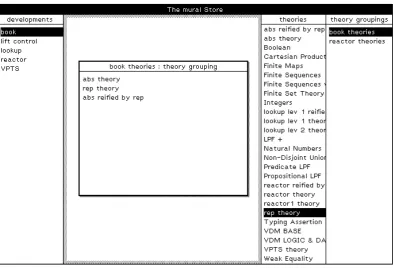
[image:24.595.88.483.248.516.2]The top-level access to both the proof assistant and the VDM support tool is provided by the store tool(Figure 2.1). Access to the proof assistant is via the right-hand side of this tool, whilst its left-hand side provides access to the VDM support tool.
Figure 2.1: The Store Tool
2.2
The proof assistant
The proof assistant essentially provides a way of creating and storing mathematical the-orieshierarchically such that information stored in one theory can be inherited by other theories. A list of (the names of) all the theories currently stored is displayed in the store tool, and new theories can be added or existing ones displayed, renamed or removed from there.
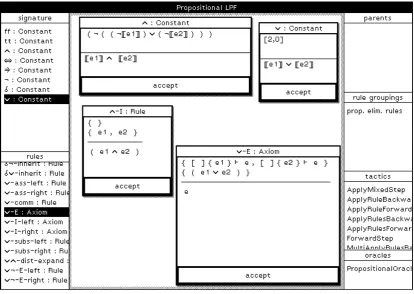
2.2 The proof assistant 15 components. Figure 2.2 shows the theory tool for propositional LPF2which will be used for illustration throughout the beginning of this chapter.
Figure 2.2: The Theory Tool for Propositional LPF
A theory has three main components: asignature, a set ofaxiomsand a set ofrules. The signature records the declarations of the symbols which can be used to construct valid formulae in the theory, whilst the axioms record the ‘primitive’ properties of these symbols, that is those properties which are accepted as being true without proof. Addi-tional properties of the symbols which do require proof are represented by the theory’s rules. Rules having a complete proof can be thought of asderivedrules, those having an incomplete proof asconjectures.
Symbols can be declared as ‘primitive’, in which case their declaration simply records their arity (the number of arguments they expect), or they can be defined in terms of
other symbols by giving the formula representing that definition. Thus, for example, the constants ¬ (not) and ∨ (or) are primitive constants in propositional LPF, having declarations(1,0)3 and(2,0) respectively. The constant ∧ (and), on the other hand, is defined in terms of¬ and∨via:
∧ 7→ ¬(¬[[e1]]∨ ¬[[e2]])
Theexpression placeholder[[ei]], i=1,2 represents theith (expression) argument of the defined symbol∧(you can think of the definition asa∧b4¬(¬a∨ ¬b)if you prefer – the placeholders simply represent arbitrary values ofaandb). The symbol∧thus expects two (expression) arguments according to this definition.
Axioms and rules represent valid logical deductions inmural. In general they consist of a set ofhypothesesand aconclusionand are to be interpreted as a statement that their conclusion is a direct logical consequence of their hypotheses, alternatively that if all their hypotheses are, or can be proved to be, true then their conclusion is, or can be proved to be, true also.
In mural axioms and rules are written with their hypotheses and conclusion respec-tively above and below a horizontal line. Thus, for example, the axiom ∨-I-right (‘or introduction on the right’) of propositional LPF is written as:
∨-I-right A
A∨B
and effectively states thatA∨Bis true ifAis true.
Axioms and rules can also have sequents as well as expressions4 amongst their hy-potheses. A sequent consists of a set ofpremises, each of which is an expression, and an
upshot, which is also an expression, and is generally written
premises`upshot
The axiom∨-E(‘or elimination’) in propositional LPF contains sequent hypotheses:
∨-E A∨B, A`C, B`C
C
Here the interpretation is that the conclusion C is true if A∨B is true and if C can be shown to be true by assuming first thatAis true and second thatBis true. The premises of each sequent thus represent additional local hypotheses which can be assumed to be true when attempting to show that the sequent’s upshot is true.
Actually, axioms and rules are considerably more powerful than the above might have implied as the symbols A, B and C appearing in the examples don’t stand for specific
objects but instead representanyobject, that is they can themselves be complex expres-sions. Inmural-speak they’remetavariables5 and the axioms∨-I-right and ∨-E in fact represent valid deductions for any expressionsA,BandC.
Generally axioms are only needed to express the primitive properties of primitive symbols – all properties of defined symbols are usually provable and thus appear as rules.
3The 1 represents the number ofexpressionarguments, the 0 the number oftypearguments. More about expressions and types later, but for the moment just ignore types.
4For a full description of how to construct expressions inmural see Section 4.2 or the full formal
specification in Appendix C.
2.2 The proof assistant 17 Thus, for example, the standard introduction and elimination properties for the symbol∧ appear as (derived) rules inmural when∧is defined in terms of¬ and∨as above:
∧-E-left A∧B
B
∧-E-right A∧B
A
∧-I A, B
A∧B
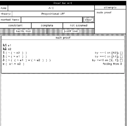
[image:27.595.103.528.307.728.2]These are proved from the definition of∧and the axioms for the primitive constants¬ and∨. As an example, the proof of the rule∧-Iis shown in Figure 2.3.
The proof assistant is extensible in that a user can at any stage add new theories to the store using the store tool or new symbol declarations, axioms and rules to an existing the-ory using the appropriate thethe-ory tool. This latter is particularly important as it means that the reasoning power of the system can be increased by adding (and hopefully proving!) more and more powerful rules. These can then be used in attempting to prove yet more powerful rules, and so on.
One rule that might be added to the theory of propositional LPF is the ∧∨-dist rule we’ve already met in Chapter 1:
∧∨-dist A∧(B∨C) (A∧B)∨(A∧C)
This can be added to the theory either by structure editing a template rule or by simply typing the required expressions into the template and invoking the parser. Its proof can then be attempted with the help of theproof tool.
A proof consists of a set ofhypotheses, which can include both sequents and expres-sions, a list of linesandboxes, and a conclusionwhich is also a line. A line consists of an expression and ajustificationof that expression in terms of some deduction applied to preceding lines, boxes and hypotheses. A box has the same components as a proof except that its hypotheses must all be expressions. The hypotheses and conclusion of a proof should be the same as those of the rule it purports to prove, and the proof is said to be complete if and only if its conclusion has been shown to be a direct logical consequence of its hypotheses.
The proof tool supports five different kinds of justification, though justification by the application of a rule is by far the most commonly used. It also supports three distinct modes of reasoning, namely forward, backward and mixed reasoning. These are best illustrated by returning to the example and showing how the proof of ∧∨-distmight be constructed inmural.
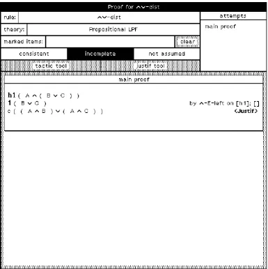
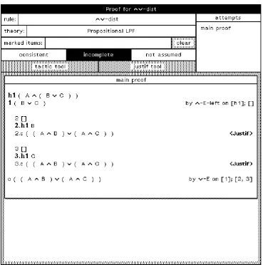
When the∧∨-distrule is added to the theory of propositional LPF a template proof is automatically attached to it. This is shown in Figure 2.4. The hypotheses and conclusion of this proof are the same as those of the rule, and it has no lines or boxes.
The bold-face (null!) justification<Justif>indicates that the justification of the con-clusion line is incomplete6. Bold-face line numbers, on the other hand, indicate knowns
of the proof, that is lines which have been shown to be direct logical consequences of the proof’s hypotheses. Currently the only known is the hypothesish1 itself!
The first step in the construction of the proof might be to apply the∧-E-left rule to the hypothesis h1. This can be done using thejustification tool, a sub-tool of the proof tool which essentially supports the construction of a single justification at a time.
The justification tool allows the user to designate some subset of the lines, boxes and hypotheses of the proof aslocal assumptionsand some line of the proof as alocal goaland to attempt to justify the local goal by some valid deduction applied to a set of lines, boxes and hypotheses including all the local assumptions. Additional lines and boxes which don’t appear amongst the local assumptions but which are needed as assumptions in order to make the deduction valid will be calledancillary assumptions. Cases where a local goal is designated but where the set of local assumptions is empty are instances of backward reasoning and correspond to the reduction of the local goal to subgoals. Cases in which no local goal is given and in which no ancillary assumptions are necessary constitute forward
2.2 The proof assistant 19
Figure 2.4: The Template Proof for∧∨-dist
reasoning. All other cases are instances of mixed reasoning.
Justifications built using the justification tool are only actually incorporated into the proof when the user presses an ‘update proof’ button within it. The justification tool thus provides a means of exploring the consequences of different sequences of actions before the actions are actually performed. In this way, the user might investigate the effect of changing the local assumptions, the local goal, the rule being applied, or indeed try to use a different type of justification altogether before selecting which seems to be the ‘best’ combination. In each case the tool will show both any necessary ancillary assumptions and, in cases where no local goal is designated, anew conclusion. When the user chooses to update the proof, the ancillary assumptions will be added to the proof as new unjustified lines and boxes. In addition, either the local goal will be justified by the justification just constructed or the new conclusion will be added to the proof justified by that justification, whichever is appropriate.
as-sumption and no local goal will be designated. Selecting the∧-E-left rule from the list of available rules will then cause the justification tool to display the expression B∨C
[image:30.595.91.477.224.611.2]as a new conclusion. This will be added to the proof as line 1, justified by applying the∧-E-left rule to the hypothesish1, when the proof is updated (see Figure 2.5). Note that the line has a bold-face line number, indicating that it is a known of the proof.
Figure 2.5: The Proof for∧∨-distafter first step
2.2 The proof assistant 21 of the proof, linec, as the local goal and invoking this facility shows that there is only one rule which could possibly be used to try to justify the conclusion line from a set of assumptions including line 1, namely the∨-Erule7.
Figure 2.6: The Proof for∧∨-distafter second step
Selecting this causes the justification tool to display two ancillary assumptions, in fact the two sequents
B`(A∧B)∨(A∧C)
C`(A∧B)∨(A∧C)
These appear as boxes when the proof is updated, the premises of the sequent forming
7Assuming that the theory of propositional LPF only contains its axioms and the introduction and
the hypotheses of the box and the upshot of the sequent the conclusion of the box. The proof after this step is shown in Figure 2.6. Note that the conclusion line does not have a bold-face line number as its justification depends on unproven assumptions, namely the two boxes 2 and 3 just added8.
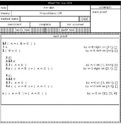
[image:32.595.92.480.214.610.2]A series of similar manipulations results in the complete proof shown in Figure 2.7.
Figure 2.7: The Complete Proof for∧∨-dist
2.2.1
Advanced topics
So far we’ve only considered building a simple proof by a series of applications of rules. In fact the proof assistant is much more powerful than this in many ways.
2.2 The proof assistant 23 Other kinds of justification
The proof assistant supports four other types of justification in addition to justifica-tion by the applicajustifica-tion of a rule:
justification by application of a sequent hypothesis
Sequent hypotheses can be used in justifications in a similar way to rules ex-cept that no substitution for their metavariables is allowed. Thus, for example, the sequent hypothesisA`Bmay be used as a valid justification of the lineB
from the lineAas in
n A
n+1 B by seq hypA`Bonn
but would not be a valid justification in any other case. justification by unfolding a definition
When a line in a proof contains an expression in which defined symbols occur, the definitions of those symbols may be expanded. The line with the expanded definition is justified by unfolding the definition on the other line, as in the ex-pansion of the definition of∧in
n A∧(B∨C)
n+1 ¬(¬A∨ ¬(B∨C)) by unfolding fromn
justification by folding a definition
The reverse of the above, that is the replacement of an expanded definition by its contracted form. Note that the system helps with the construction of both this and the previous kind of justification by highlighting the subterms of the expression which are foldable or unfoldable, whichever is appropriate. justification by oracle
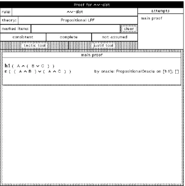
An oracle is essentially a piece of raw Smalltalk code which is attached to a theory and which can decide whether or not a particular deduction is valid in that theory. Oracles are based on the axioms of the theory but don’t make use of them in any real sense, so care has to be taken to ensure that oracles remain in step with changes to the axioms9. There’s actually not much we can do to enforce this automatically, just as there’s no way of enforcing that you don’t build a theory with an inconsistent set of axioms, unfortunately. However, there’s currently no interface to allow general users to add oracles to the system so you have to make do with the one that’s there. By an amazing coincidence, this is one for propositional LPF! Using this, all the hard work expended on that wretched proof of∧∨-distcould have been avoided and the proof could have been done in a single step! (see Figure 2.8).
Multiple proof attempts
If you get stuck whilst trying to do a proof you might like to set it aside and try a different approach. The proof tool supports this by allowing multiple attempts at a proof to coexist. One attempt is designated themain attemptand this is the one with
9In principle there would be nothing to stop one writing an oracle which simply returned ‘true’ for
Figure 2.8: The Proof for∧∨-distusing the Oracle
which the proof tool interacts. However, you can at any stage make new attempts, either as copies of existing attempts or as new template proofs, and you can switch the designation of the main attempt at will.
In-line lemma creation
2.3 The VDM support tool 25 justifications in the proof appeal to unproven lemmas10.
Naturally, the proof tool also provides a facility whereby all unproven lemmas on which a proof depends can be found. It also keeps track of the dependency rela-tionship between rules induced by this facility and doesn’t allow circularities in this dependency relationship to develop.
Tactics
So far we’ve only considered the process of building a single justification at a time. However,mural also provides atactic language, which allows users to writetactics
and attach them to theories, and atactic tool, another sub-tool of the proof tool, for running them.
Tactics effectively provide a means of encoding and parametrizing commonly used proof strategies; for instance, a tactic might be written which steps through a list of rules and attempts to apply each rule in turn somewhere in the proof. In this way it is possible for a tactic to perform many steps of a proof. However, it is also possible to make a complete mess of a proof with tactics, for instance by asking a tactic to apply a rule that is always applicable as often as it can11. For this reason the tactic tool copies the current main proof attempt before it runs the tactic and then works on the copy. It also displays some information as the tactic executes. If things do go awry you can always stop the execution and throw the copied attempt away. Removal of garbage
When (the main attempt of) a proof is complete, the proof tool offers a garbage collectionfacility which goes through the proof and throws out any redundant lines and boxes, that is lines and boxes which are not crucial to the logical completeness of the proof. It also throws out all other proof attempts.
2.3
The VDM support tool
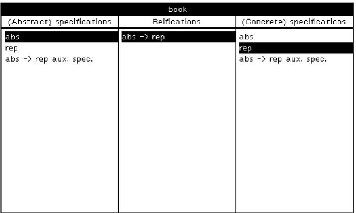
The VDM support tool provides facilities for creating and storing specifications and reifi-cations between specifireifi-cations in VDM12. Related13 specifications and their associated reifications are grouped together asdevelopments, which are added, accessed, renamed and removed via the store tool (see Figure 2.1). The left-hand column of the store tool displays a list of (the names of) all the developments currently stored in the system.
A development is built using thedevelopment tool, which lists the specifications and reifications making up a particular development and allows new ones to be added and old ones to be displayed, renamed or removed. Figure 2.9 shows the development tool for the development described in Section 1.2, which will be taken as the example development throughout the remainder of this chapter.
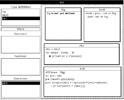
A general VDM specification consists of a set oftype definitions, a set ofconstant def-initions, a set offunction definitions, astate definition(optional), and a set ofoperations. These are built or edited with the help of the spec tool (see Figure 2.10). The various
10Note that this appeal might be direct or indirect, e.g. all lemmas used in the justifcations in the proof
itself might have complete proofs but these proofs might appeal to unproven lemmas, etc.
11I once created a line in a proof with 14¬’s in it by applying the¬ ¬-Irule in exactly this way! 12Actually a subset of BSI standard VDM.
Figure 2.9: The Development Tool
components of the specification are listed down the left-hand side of the tool under the appropriate headings, whilst the right-hand side of the tool provides an area for displaying and editing them. The various components are constructed by structure editing a template object of the appropriate kind.
The abstract specification in our example development contains three14 type defini-tions (Abs0, Abs and Sig) and one operation (ADD). These are shown displayed in the spec tool in Figure 2.10. Note that there is no need for a separate function definition describing the invariant inv-Abs on Abs as this is included as part of the definition of
Abs. If the form of the other declarations contains the least element of surprise, however, you are advised to go back and read Section 1.2 before continuing. On the basis of this, you should be able to work out for yourself what the components of the corresponding concrete specification look like15.
Having built the two specifications, you have to return to the development tool to designate the concrete specification as a refinement of the abstract specification. This is done by selecting the two specifications in the left and right portions of the tool as appropriate and adding a reification. You can then use the reif tool and the op model toolto build the retrieve function16 and to designate the operationADDRin the concrete specification as the concrete form of the abstract specification’s operationADD.
14Note that an alternative formulation would have been to makeAbsthe state and not a type definition. 15If not you might as well give up now!
2.4 Reasoning about developments 27
Figure 2.10: The Spec Tool
2.4
Reasoning about developments
It is, of course, perfectly feasible to reason informally about a development as it stands simply by using your knowledge of what its various components ‘mean’. Indeed, you probably do so, even though you might not think of it in those terms, when you’re writing each specification and reification, at least to the extent of trying to convince yourself that the whole thing hangs together properly. On the other hand, it is very difficult to reason formally about it in its current form as we have no formal language in which to do so. We thus have to somehow extract the ‘meaning’ we use in our informal reasoning in a form which does admit formal reasoning. This facility is provided inmural in the form of a mechanism whereby a specification or a reification in the VDM support tool can be ‘translated’ automatically into a theory supporting reasoning about it in the proof assistant17.
One thing we have to consider here is that the components of a particular development are built up not only out of user-defined type, constant and function definitions but also out of the ‘primitive’ constructors of the specification language itself. Thus, for example,