www.ijiset.com
279
Optimization of Fir Filters using MCM and CSE Techniques
P
1
P
Pankaj Gupta, P
2
P
Mandeep Kaur
R1R
Research Student, R
2R
Assitant Professor
Department Of Electronics and Communication Engineering, Punjabi University Patiala.
0T
Abstract
0T0T
The Finite Impulse Response (FIR) filter is a digital filter widely used in Digital Signal Processing applications in various fields like imaging, instrumentation, communications, etc.However, in realizing a large-order filter many complex computations are needed which affects the performance of the common digital signal processors in terms of Area, Power, speed, cost, flexibility, etc.Multiple Constant Multiplication (MCM) and Common Sub expression Elimination (CSE) techniques are extremely effective to improve overall system performance. The FIR filter implementation using MCM and CSE techniques reduce the Area of filter by reducing the number of operators.
0T
In this paper, FIR filter is implemented using MCM and CSE techniques. Direct-form approach in realizing a digital filter is considered. MCM and CSE approach gives a better performance than the common filter structures in terms of speed of operation, cost, and power consumption in real-time. The FIR filter simulated with the help of Xilinx ISE (Integrated Software Environment) 14.5.
For the realization of FIR filter using direct form, FDA (42TFilter Design and Analysis)42T tool can also be
used. For an N order filter the number of shift register and adders required is N and the number of multipliers required is N+1 in direct form. These filters can work in real time.
0T
Keywords: MCM, CSE, CSD, FIR, IIR, BSE
0T
1. INTRODUCTION
1.1 Filter: Filtering plays an important role in digital signal processing. The process of filtering is widely used in a number of electronic devices to remove a part of signal that damages the signal [16]. The following is the diagram of filter which gives the basic information:-
Figure 1: Block diagram of Filter
A Filter is a network which can change the wave shape, amplitude, phase, frequency and other characteristics of the signal in a desired manner. The main purpose of using the filter in digital signal processing is to improve the quality of a signal by reducing noise, to extract or to combine the desired portion of signal [17].
Filters are used for two purposes: one for separation of signal and for restoration of signal. Signals which are damaged by interference and noise require different techniques to get noiseless signal. A device is used to measure the electrical activity of heart of a baby inside the mother’s womb will be damaged by breath and heartbeat signal of the mother. Filters are used at that time to separate the signals and to analyze them individually. When the signal gets corrupted, then restoration of signal is used [16]. Recording of Audio signal which is made with poor equipment is filtered to give the better sound signal output than the originally it produced. When filters are implemented, the coefficient multiplier is the most complex and the slowest component. The cost of implementation of an FIR filter can be reduced by decreasing the complexity of the coefficients.
1.2 Types of Digital Filter: There are two types of digital filters in digital signal processing: one is Finite Impulse Response (FIR) and other is Infinite Impulse Response (IIR).
1.2.1 Finite impulse Response (FIR)
Finite Impulse Response (FIR) digital filter is mostly used in digital signal processing (DSP) applications that are speech processing, loud speaker equalization, echo cancellation, adaptive noise cancellation and various communication applications. FIR means “Finite Impulse Response”. If an impulse is given to filter which is a single "one (1)" sample followed by number of “zero (0)" samples then zeroes will come out after "one (1)" sample which makes the way through the delay line of the filter. So 1TFIR filter
1T
has1T1Tfinite1T1Tduration impulse response because it settles
www.ijiset.com
280
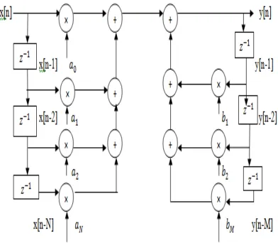
and are inherently stable [18].FIR filters are linearphase filters. There is a condition needed to achieve the Linear Phase. The condition is when the filter’s phase response is a linear function of frequency, which results in the delay through the filter is same at all frequencies. Thus the filter does not create any type of “phase distortion” or “delay distortion”. A FIR filter is linear phase if the coefficients of a filter are symmetrical around the centre coefficient. It means that first coefficient is same as the last coefficient. Similarly the second coefficient is same as the next to last. Therefore filter should have odd number of coefficients because a single coefficient which is at centre has no mate.FIR filters have great flexibility in shaping their magnitude response. The following is the block diagram of FIR filter which gives the basic idea:-
Figure 2: A direct form of FIR Filter
For a FIR filter of order M, each value of the output
sequence is the weighted sum of the most recent
input values:-
Where,
x[n] is the input signal, y[n] is the output signal, M is the order of filter 𝑎𝑖 is coefficient of filter
.
FIR filters are known as non recursive filters because filter output does not depend on previous output.
1.2.2. Infinite impulse Response (IIR) “IIR” means Infinite Impulse Response. If an impulse is applied to
filter which is a single "one (1)" sample followed by number of “zero (0)" samples then an infinite number of non-zero values will be come out. Filter’s impulse response will be infinite because of the presence of feedback in the IIR filter [19]. The following is the diagram of IIR filter which gives the basic idea:
Figure 3: A direct form of IIR Filter
For a IIR filter, each value of the output sequence is:-
Where x[n] is input signal,y[n] is output signal,M is the order of feedback filter,N is the order of feedforward filter, 𝑎𝑁 is cofficients of feedforward filter and 𝑏𝑀 is coefficients of feedback filter.
2. OPTIMIZATION OF FILTERS
FIR filters are inherently stable and require no feedback. Major factors that influence choice of a specific realization of filter are computational complexity, requirement of memory and finite word length effects. Filter optimization 1Tis1T the process of
designing a1T1Tsignal processing filter1T1Tthatsatisfies a set
www.ijiset.com
281
and Common Sub expression Elimination (CSE)Techniques [20].The multiple constant multiplication (MCM) is defined as a technique to find out the minimum number of adders and sub tractors required for the multiplication of multiple constants by an input variable. The CSE is defined as a technique to find out the minimum number of addition and subtraction operators by taking operators as common [21].
3. Literature Survey
There is a lot of work that has been done in the field of FIR filters. There is a lot of work has been done in this field by using different techniques and motives to provide the best system. Researchers have used the different techniques and parameters to provide the best output and performance in any situation. The literature survey of different researchers has been given
below:-Michael A.Soderstrand et al. (2000) in [1] proposed a hardware optimization technique based on minimum adder Canonical Signed Digit (CSD) multiplier blocks is combined with a technique for trading adders to reduce hardware requirements for FIR filter coefficients. Noise free filters can only be achieved using FIR filters because FIR filters can always designed by using sufficient number of bits in the multipliers that rounding or truncation after multiply is not necessary. Thus an idea is carried out by increasing the filter order and decreasing the bits to minimize the hardware requirement. This technique is implemented in Field Programmable Gate Array (FPGA) which is an integrated circuit and it requires high cost.
J. Yli-Kaakinen and T. Saramaki (2001) in [2]
have proposed a systematic Multiple Constant Multiplication (MCM) algorithm that minimizes a number of adders to implement an overall filter to meet amplitude criteria. This algorithm performed in two steps: First a Linear Programming algorithm is used to determine the parameter space of coefficients of filter. Second step involves finding the filter parameters to meet amplitude criteria. In this algorithm, it’s very difficult to maintain the amplitude. Small change in amplitude will create quantization error which affects the performance of FIR filter.
Paulo Flores et al. (2005) in [3] represented an exact algorithm which helps to maximize the sharing of partial terms in Multiple Constant Multiplication (MCM) technique. They model a Boolean Network which takes all possible partial terms by using AND and OR gates. An AND gate represents as an adder or a sub tractor. The output of AND gates is summed by OR gates. This algorithm uses binary and Canonical Signed Digit (CSD) representations to represent the
coefficients. Converting coefficients into Binary form, shifting and adding the partials and then converting into Canonical Signed Digit (CSD) will be more complex and take more time to represent a coefficient.
S.Vijay et al. (2007) in [4] represented the complexity of Finite Impulse Response (FIR) filters and reduced by using number of adders and sub tractors for implementation of coefficient multipliers. A Common Sub expression Elimination (CSE) algorithm with a based on the Canonic Signed Digit (CSD) representation of coefficients of filter for implementing low complexity FIR filters. In Common Sub Expression Elimination (CSE), first write the expression in binary form. According to bit position, shift the variable and added up the shifted variable. Then maximizes grouping of the sub expressions for the reduction of operators.Canonical signed digits used where there is occurrence of consecutive non zero digits. Steps of converting a binary number into canonical digits repeated again and again until there is no consecutive non zero digits. Thus it’s very difficult to deal with canonical signed digits
.
Oscar Gustafsson (2007) in [5] has represented Multiple constant multiplication (MCM), realizing a number of constant multiplications using a minimum number of adders and sub tractors. An adder graph type algorithm for solving the MCM problem was introduced .In MCM, multiplication of each constant was done by using addition, subtraction and shift operators. In MCM, first write expression in binary form. According to bit position, shift variable and added up the shifted variable. In Adder Graph, adding and shifting and random grouping of sub expressions is used to reduce the number of operators. By using MCM with Adder graph, numbers of operators are reduced but there is no rule to common the block to reduce the number of operators.
R.Mahesh and A.P.Vinod (2008) in [6] have represented the Common Sub expression Elimination (CSE) technique which is based on Canonical Signed Digit Coefficients (CSD).With the help of these, the number of operators can be reduced to realize the multipliers when the filter coefficients are represented in binary form. The reduction of operators can be achieved from this method but this is only for short filters .If there is large number of coefficients in a filter then it creates difficulty to represent coefficients in Canonical Signed Digit form. Because method to represent the coefficients into CSD form is very long.
www.ijiset.com
282
efficient Finite Impulse Response (FIR) having alinear phase .This algorithm finds the coefficients of filter with reduced number of signed power of two terms. In this algorithm, fix a coefficient up to a certain value which is determined by the coefficient’s boundary values using linear programming. This algorithm requires less number of operators and consumes less power. But this algorithm is used only when there is odd number of coefficients to fulfill the condition of linear phase Finite Impulse Response (FIR).
Levent Aksoy et al. (2008) in [8] have represented a exact Common Sub expression Elimination (CSE) for sharing terms in Multiple Constant Multiplication (MCM).This algorithm deals with the Boolean networks to cover the all terms which generate the set of coefficients in Multiple Constant Multiplication (MCM).Linear Programming is used to reduce the number of gates used in it. This algorithm handles the binary and Canonical Signed Digits (CSD) representations for the coefficients. This paper results the reducing in delay but area of filter is increased. So this algorithm is not efficient to decrease the number of operators.
Chip-Hong Chang et al. (2008) in [9] have presented a new methodology to reduce the number of operators in Finite Impulse Response (FIR) digital filters. An adder graph like data structure called Multiroot Binary Partition Graph (MBPG) in which a set of coefficients is partitioned into symbols for the common sub expression elimination. A minimum number of different pairs or group of symbols can be used to code a set of coefficients based on their probability and conditional probability of occurrence. This algorithm will reduce the critical path delay, complexity of a filter and consume power. But this algorithm will be lengthy for high order finite impulse response filters.
Mathias Faust and Chip-Hong Chang (2009) in [10] were proposed Transposed Direct form of FIR filter instead of simple Direct form of FIR filter to optimize the coefficients by reducing the number of operators in Multiple Constant Multiplication (MCM) technique. Transposed Direct form is used over Direct form because of its shortest path delay. In Direct form, input is delayed before the coefficient multiplication. In Transposed direct form, sum generated by the outputs of coefficient multiplier, are delayed. So large numbers ofregisters are required in Transposed direct form. The delay through the structural adders is reduced except last tap. The one
full adder delay increased for the last tap which will be tolerable and will not affect the performance of a filter. Area of filter reduced by reducing the delays through structural adders but require more number of
registers. Thus there is tradeoff between Area of filter and Cost of Filter.
Guifeng Liu et al. (2010) in [11] have represented an approach to reduce the quantization noise in Multiple Constant Multiplication (MCM) while maintaining the performance and reduce the area of filter. In Multiple Constant Multiplication (MCM), some of information is lost called round off noise due to the presence of adders and sub tractors. But the shifts do not contribute to any noise because they are realized using wiring. To reduce the round off noise, add more bits to the appropriate nodes. When numbers of bits are added to the nodes of Multiple Constant Multiplication (MCM) block then quantization noise will be decrease but there is increase in area of filter. More bits means more accuracy and more space is used. Thus there is effectively tradeoff between filter
performance
and implementation area.
Kenny Johansson et al. (2011) in [12] have represented a graph based minimum adder depth algorithm for Multiple Constant Multiplication (MCM) technique which reduces the area of filter and power. If adder depth will low then efficient area of filter and power consumption can be done. This algorithm uses shift operators, adders/sub tractors operators and graph adders to reduce the power and Area of filter. Graph based algorithm is efficient algorithm to get low adder depth but it is not used for Cascaded adders because they have large adder depth. The number of cascaded adders strongly effects the power consumption.
L.Aksoy et al. (2013) in [13] have represented the design of low complexity using bit-parallel multiple constant multiplications (MCM) operation which reduces the complexity of many digital signal processing systems. In digital-serial design, input data is divided into the number of bits. Then it processed the data serially bit by bit but applies each bit in parallel. Digital–serial computation plays an important role when bit serial implementations can’t meet the delay requirements then bits sends in parallel need more hardware. FIR filters which are under the shifts-adds architecture having significant area reduction as compared to that filter design which is implemented by using digital serial constant multiplier. Some attention had been given to the digit-serial MCM design which offers low complexity MCM operation at the cost of an increased delay. Thus it was a tradeoff between time and Area of filter.
www.ijiset.com
283
(MCM) operation. Multiple constant multiplicationsused Binary Signed Digit (BSD) number system to design the coefficients. The Binary signed digits (BSD) used in this paper which gives a better performance over Canonical Signed Digits (CSD).BSD representation is used to find the possible decompositions which results the possibility of finding MCM realizations with minimum logic depth is increased because the sub expression space becomes large. In BSD, first a decimal number is converted into binary digits. Each digit associated with a sign, positive or negative. So a decimal number can be represented in many ways using Binary Signed Digits. Thus BSD show redundancy.
Levent Aksoy et al. (2014) in [15] have represented Multiple Constant Multiplication (MCM) which realizes the multiplication of constants by a variable. It can be implemented by using generic multipliers and adders/sub tractors. This algorithm is implemented by Field Programmable Gate Arrays (FPGA) using Linear Programming Formulation and Graph Based algorithm. The use of Multiple Constant Multiplication (MCM) design leads to FIR filter design requiring less number of operators, having less delay and consuming less power with respect to those include only adders/sub tractors. But due to the further use of large number of algorithms this becomes more complex.
4. Multiple Constant Multiplications (MCM)
Existing optimization algorithms for the multiplier less realization of multiple constant multiplications (MCM) typically target the minimization of the number of addition and subtraction operations [23]. Multiple constant multiplication (MCM) is defined as a technique to find out the minimum number of addition/subtraction operations required for the multiplication of multiple constants by an input variable [24]. Multiplier Constant Multiplications is a straight forward way of realizing the constant multiplications under a shift-adds architecture. It is first to define the constants under a particular number representation, and second, for the nonzero digits in the representation of the constant, is to shift the input variable according to the digit positions and add/subtract the shifted variable with respect to the digit values [25].Taking a simple example, consider the constant multiplications 29x and 43x [26].Their decompositions in MCM are listed as follows
29x=(11101)binx=x<<x+2<<x+3<<x+4 (iii)
43x=(101011)binx=x<<x+5<<x+3<<x+1 (iv) These coefficients are implemented as follows using
Multiple Constant Multiplication (MCM):
Figure4: Implementation of coefficients in MCM form
In this, x is input signal.”<<” sign represents the shifting of variable. Its shifts the variable by two raised to the power. In this MCM technique only six adders are used to implement two coefficients instead of using a number of multipliers. However, the sharing of common partial products in the shift adds architecture allows for large reductions in the number of operations and also reduction in area and power dissipation of the MCM designs [22].
5. Common Sub expression Elimination (CSE)
A Common Sub Expression Elimination (CSE) technique is advanced technique of Multiple Constant Multiplication (MCM) in which maximum sharing of variable is done to reduce the number of operators so that area of filter can be reduced. Common Sub expression Elimination technique is simply a shifting and adding of variable to implement the coefficients. First a decimal number is converted into binary form. Shift the input variable according to the digit position and then add/subtract the shift variable according to the coefficient value. It can be explained clearly by taking the same example as in Multiple Constant Multiplication (MCM) technique. Taking a simple example, consider the constant multiplications 29x and 43x [26].Their decompositions in CSE are listed as follows
29x=(11101)binx=x<<x+2<<x+3<<x+4 (v) 43x=(101011)binx=x<<x+5<<x+3<<x+1 (vi) In above, 11 and 101 both are used for sharing of
www.ijiset.com
284
Figure 5: Implementation of coefficients in CSE form [13]
In this, x is input signal.”<<” sign represents the shifting of variable. Its shifts the variable by two raised to the power. In this CSE technique only four adders are used to implement two coefficients whereas in Multiple Constant Multiplication (MCM) six adders are used. However, the maximum sharing of common partial products in the shift adds architecture allows for great reductions in the number of operations. Use of sub tractor instead of adders will reduce the cost of FIR filter. Common Sub expression Elimination (CSE) technique gives the efficient decrease in the area of FIR filter which gives the better performance of FIR filter.
6. IMPLEMENTATION
In this, FIR filter is implemented using direct form. FIR filter’s Direct form uses large number of operators which increases the area of filter. In this, different parameters like area, delay and memory requirement are described using Xilinx.
6.1 Device Utilization Summary
Figure 6 describes the device utilization summary. This summary gives the idea about number of operators .It tells that how many operators are available, how many operators are used. Simply this gives the knowledge about area of filter. Area of filter can be finding by count the number of slice flip flops, number of input LUT’s and number of shift registers. Less number of these operators, less will be the area of filter.
Figure 6: Device Utilization Summary of FIR filter using direct form
In this, Total 408 operators are used to implement FIR filter using direct form.
Figure 7: Device Utilization Summary of FIR filter using MCM and CSE
In this, Total 152 operators are used to implement FIR filter using MCM and CSE
www.ijiset.com
285
Figure 8 shows memory used by these operators.Total memory used by operators is 278684 kilobytes .
Figure 9: Total memory used by FIR filter using MCM and CSE
6.2 Timing Summary
Figure 8 gives the timing summary. With the help of timing summary, delay and speed of filter can be calculated. If delay will be less then speed will be more. Minimum delay will give the better performance of FIR filter. Delay is calculated in nano seconds. Delay Period of FIR filter is 5.140 ns.
Figure 10: Timing Summary of FIR filter using direct form
Figure 11 gives the timing summary of FIR filter using MCM and CSE. Delay Period of FIR filter is 1.749 ns.
Figure 11: Timing Summary of FIR filter using MCM and CSE
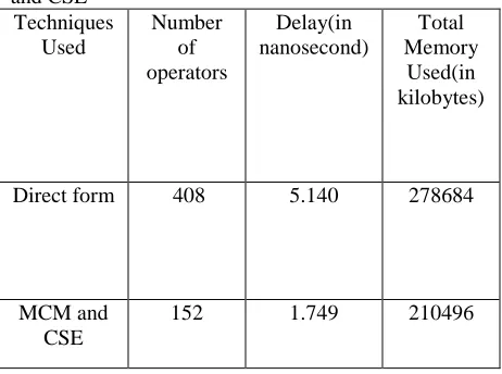
7. COMPARISON OF DIRECT FORM AND MCM, CSE
There is reduction of operators using MCM and CSE for the implementation of FIR filter. Thus the area of filter is reduced using MCM and CSE. Memory used and delay also decrease using MCM and CSE. In table 1, a comparison between direct form and MCM, CSE is given:
Table 1: Detailed dimensions of Direct form, MCM and CSE
Techniques Used
Number of operators
Delay(in nanosecond)
Total Memory
Used(in kilobytes)
Direct form 408 5.140 278684
MCM and CSE
152 1.749 210496
8. CONCLUSION
During the last decade, digital communication industry has grown at a very fast rate. With the rapid development of digital communication system, different techniques for the optimization of FIR filters have attracted considerable attention. They are commonly used in digital signal processing system. Due to these reasons the demand for FIR filters has increased. With the advancement of technology, communication devices such as radios in which more noise is present, thus the largenumber of filters to be used in such devices to remove the noise. Thus the purpose of this thesis work is to analyze and design the optimization techniques to reduce the area of filter, delay and power. So that signal can process at fast rate. A direct form, MCM and CSE techniques for the optimization of FIR filters are presented. Compare to many techniques, these techniques are designed based on a simple structure and suitable for optimization of FIR filters. The proposed techniques are considered to achieve minimum area, delay and power of filter using less number of operators, so it can give fast rate to process a signal. The measured results show that the in case of
www.ijiset.com
286
MCM and CSE, number of slice flip flops are 39,number of input LUTs are 32 and number of occupied slices are 23.Thus total number of operators used are 152.The minimum period is 1.749 ns.Total memory used by operators used to implement a FIR filter is 210496.
Thus the reduction of area, delay and power is there when Multiple Constant Multiplication (MCM) and Common Sub expression Elimination (CSE) are used. In addition, the proposed techniques are easily implemented and give a better response of FIR filter. These techniques can be used widely in digital signal processing.
REFERENCES
1. Michael A.Soderstrand ,Louis G.Johnson,Hary Arichanthiran,Mezbaul D.Hoque and Raja Elangovan,”Reducing Hardware Requirement In FIR Filter Design”in Proc.IEEE ISCAS,2000,pp.3275-3278.
2. J. Yli-Kaakinen and T. Saramaki, “A systematic algorithm for the design of multiplierless FIR filters,” in Proc. IEEE Int. Symp. Circuits Syst.,vol.2 May 2001, pp. 185–188.
3. Paulo Flores, Jos´e Monteiro and Eduardo Costa,” An Exact Algorithm for the Maximal Sharing of Partial Terms in Multiple Constant Multiplications” in Proc.IEEE ISCAS, 2005, pp.13-16
4. S.Vijay,A.P.Vinod,Edmund M-K.Lai, ”A Greedy Common Sub expression Elimination Algorithm for Implementing FIR Filters" in Proc. IEEE ISCAS,May 2007,pp.3451-3454
5. Oscar Gustafsson,”A Difference Based Adder Graph Heuristic for Multiple Constant Multiplication Problems" in Proc.IEEE ISCAS, May 2007, pp.1097-1100
6. 21. R. Mahesh and A. P. Vinod,” A New Common Subexpression Elimination Algorithm for Realizing Low-Complexity Higher Order Digital Filters” IEEE Trans.Very Large Scale Integration (VLSI) Syst.,vol.27, no.2,pp. 217-229,Feb.2008
7. Mustafa Aktan, Arda Yurdakul, and Günhan Dündar,” An Algorithm for the Design of Low-Power Hardware-Efficient FIR Filters” IEEE trans.ckts.syst.I, vol.55,no.6,pp.1536-1545,july 2008 8 .Levent Aksoy, Eduardo da Costa, Paulo Flores, and José Monteiro,” Exact and Approximate Algorithms for the Optimization of Area and Delay in Multiple Constant Multiplications,” IEEE Trans.Computer Aided Design of Integrated Ckts and Syst.,vol.27, no.6,pp. 1013-1026,June 2008
9. Chip-Hong Chang, Jiajia Chen and A. P. Vinod,” Information Theoretic Approach to Complexity Reduction of FIR Filter Design” IEEE trans.ckts.syst.I, vol.55,no.8,pp.2310-2321,Sept 2008
10. Mathias Faust and Chip-Hong Chang,” Optimization of structural adders in fixed coefficient transposed direct form FIR filters” in Proc.IEEE ISCAS,2009, pp.2185-2188
11. Guifeng Liu , Linda S. DeBrunner , Victor DeBrunner and Kenny Johansson,” Internal Quantization in FIR filters implemented using Multiple Constant Multiplications” in Proc.IEEE ISCAS,2010, pp.1284-1287
12. Kenny Johansson, Oscar Gustafsson, Linda S. DeBrunner and Lars Wanhammar,” Minimum Adder Depth Multiple Constant Multiplication Algorithm for Low Power FIR Filters” in Proc.IEEE ISCAS,2011,pp.1439-1442
13.L.Aksoy,C.Lazzari,E.Costa,P.Flores,andJ.Monteir o,”Design of digit-serial FIR Filters: Algorithms,architectures,and a CAD tool,”IEEE Trans.Very Large Scale Integration (VLSI) Syst.,vol.21, no.3,pp. 498-511,Mar.2013
14. Firas Al-Hasani, Michael P.Hayes, Andrew Bainbridge-Smith,”A Common Sub expression Elimination Tree Algorithm”IEEE Trans.ckts.Syst.I, vol.60, no.9, pp.2389-2400, September 2013
15. Levent Aksoy, Paulo Flores and Jose Monteiro,” Efficient Design of FIR Filters Using Hybrid Multiple Constant Multiplications on FPGA” ” in Proc.IEEE ISCAS,2014, pp.42-47
16.D.M. Kodek, “Design of optimal finite wordlength FIR digital filters using integer programming techniques," IEEE Trans. Acoust., Speech, Signal Process.,vol ASSP-28, pp. 304-308, June1980.
17. McClellan James H. and Thomas W. Parks, “A Unified Approach to the Design of Optimum FIR Linear-Phase Digital Filters”, IEEE proceeding-circuit theory, Vol.20, pp. 697 –701, Nov 1973. 18. Basant Kumar Mohanty and Pramod Kumar Meher,” A High-Performance FIR Filter Architecture for Fixed and Reconfigurable Applications” IEEE Trans.Very Large Scale Integration (VLSI) Syst.,vol.24, no.2,pp. 444-452,Feb.2016
19. L. R. Rabiner, M.T. Dolan and J.F. Kaiser, “Some Comparisons between FIR and IIR Digital Filters”, Vol-53, Feb.1973.
20.Indranil Hatai, Indrajit Chakrabarti and Swapna Banerjee,” An Efficient Constant Multiplier Architecture Based on Vertical-Horizontal Binary Common Sub-expression Elimination Algorithm for Reconfigurable FIR Filter Synthesis” IEEE trans.ckts.syst.I, vol.62,no.4,pp.1071-1080,April 2015.
www.ijiset.com
287
published in Integration,the VLSI journal, vol 45,Issue 3, pp. 294–306, June 2012.
22. Levent Aksoy,Eduardo Costa,Paulo Flores and Jose Monteiro,” Design of Low-Power Multiple Constant Multiplications Using Low-Complexity Minimum Depth Operations”,IEEE Trans.,pp.79-84, 23. Levent Aksoy , Eduardo Costa , Paulo Flores and Jose Monteiro,” Finding the optimal tradeoff between area and delay in multiple constant multiplications” published in Microprocessors and Microsystems,vol 35, Issue 8, pp. 729–741, November 2011.
24. M.B.Gately , M.B.Yeary , and C.Y.Tang , ”Multiple real-constant multiplication with improved cost model and greedy and optimal searches,”in Proc.IEEE ISCAS, May 2012,pp.49-52.
25. Levent Aksoy , Ece Olcay Gunes and Paulo Flores,” Search algorithms for the multiple constant multiplications problem: Exact and approximate” published in Microprocessors and Microsystems,vol 33T
34, Issue 533T, pp. 151–162, August 2010.
26. Levent Aksoy,Eduardo Costa and Paulo Flores,Jose Monteiro,”Multiple Tunable Constant Multiplications :Algorithms and Applications” in Proc.IEEE ISCAS,November 2012,pp.473-479
![Figure 5: Implementation of coefficients in CSE form [13]](https://thumb-us.123doks.com/thumbv2/123dok_us/7858468.1303468/6.612.72.287.89.296/figure-implementation-coefficients-cse-form.webp)