Performance of a Dye Sensitized Solar Cell
Utilizing a Magnet
Mildred Makokha
1, David Masabule Mulati
2, James Mbiyu Ngaruiya
3, Ngei Katumo
1P.G. student, Department of Physics, Jomo Kenyatta University of Agriculture and Technology, Kenya1
Professor, Department of Physics, Jomo Kenyatta University of Agriculture and Technology, Kenya2
Doctor, Department of Physics, Jomo Kenyatta University of Agriculture and Technology, Kenya3
ABSTRACT: A comparative study of dye sensitized solar cell (DSSC), one with a magnet and the other without a
magnet, has been carried out. The current (I)-voltage (V) characteristics of the cells have been determined. For the cell with a magnet, the short circuit current density (JSC) = 8.5 mA/cm
2
, open circuit voltage (VOC) = 0.7 V, fill factor (FF) =
46.6% and efficiency (ƞ) =2.82%. For the cell without a magnet, JSC = 10.58 mA/cm2, VOC = 0.7 V, FF = 42.9% and (ƞ)
=3.18% Therefore, Nd-Fe-B magnet directly affects the performance of the solar cell. The cells were continually exposed to sunlight after fabrication for 90 days and their long term stability studied. Though the photovoltaic performance of both cells reduced with time, the cell sealed with magnets recorded a better stability
KEYWORDS: Dye sensitized solar cells, long term stability, efficiency and performance.
.
I. INTRODUCTION
The world’s energy focus has shifted from burning fossil fuels to relatively less expensive, efficient and renewable resources especially the solar energy as indicated in [1]. This is due to the fact that fossil fuel is slowly, but inevitably vanishing and produces gases that have a negative effect on environment, health and climate as stated in [2, 3] . In addition, the worldwide energy consumption is expected to double in the next four decades due to rapid population increase and technological dynamism in many developing countries as stated by Hamann et al .[4] The authors in [5] states that as a consequence of dwindling fossil fuel resources, a huge power supply gap of 14 terawatts is expected by 2050. According to Gratzel [6] solar energy, being abundant, is expected to play a crucial role as a future energy source. In an attempt to utilize the energy from the sun, scientists have deployed photovoltaics, a field of technology and research related to the devices which directly convert photons of light of specific wavelengths into electricity. The solar cell is the elementary building block of the photovoltaic technology. The solar cell is made of semiconductor materials and they include wafer-based silicon solar cells, amorphous thin film, Cadmium Telluride and dye sensitized solar cell with silicon being the main area of focus. Silicon solar cells have some shortcomings with its biggest problem being cost since they require a relatively thick layer of doped silicon in order to have reasonable photon capture rates, and silicon processing is expensive as explained by Chung et al. [7]. There have been a number of different approaches to reduce this cost over the last decade, notably the thin-film approaches, but to date they have seen limited application due to a variety of practical problems. Another line of research has been to improve efficiency through the multi-junction approach, although these cells are expensive and suitable only for large commercial deployments. Energy conversion efficiency of a crystalline silicon-based solar cell is 24.4%, which is more than twice DSSC’s which is closer to 11%.
crystal Khan et al[9]. In theory, given low rates of production, the high-energy electron in the silicon could re-combine with its own hole, giving off a photon (or other form of energy) and resulting in no current being generated.
According to Khan in [10], DSSCs work under cloudy skies and non-direct sunlight, as opposed to traditional designs which suffer a "cut out" at some lower limit of illumination, when charge carrier mobility is low and recombination becomes a major issue. The cut off for DSSC is so low they are even being proposed for indoor use, collecting energy for small devices from the lights in the house. A practical advantage, which a DSSC share with most thin-film technologies, is that the cell's mechanical robustness indirectly leads to higher efficiencies in higher temperatures. DSSCs are normally built with only a thin layer of conductive plastic on the front layer, allowing them to radiate away heat much easier, and therefore operate at lower internal temperatures. The DSSC is transparent, has a low power generation cost and can be produced in various colours.
II.LITERATURE REVIEW
A DSSC is a low-cost solar cell belonging to the group of thin film solar cells Haiying in [11]. The cell is composed of four elements, namely, the transparent conducting and counter conducting electrodes, the nanostructured wide bandgap semiconducting layer, the dye molecules (sensitizer), and the electrolyte. The transparent conducting electrode and counter-electrode are coated with a thin conductive and transparent film such as fluorine-doped-tin dioxide (SnO2).
Figure 1 below shows the structure of the DSSC:
Figure 1: The structure of solar cell [12]
Both conducting electrode (photoelectrode) and counter electrodes are made from clear glass due to its relative low cost, availability and high optical transparency in the visible and near infrared regions of the electromagnetic spectrum. Conductive coating (film) in the form of thin transparent conductive oxide is deposited on one side of the substrate. The nanostructured wide bandgap oxide semiconductor (electron acceptor) is applied on the conductive side. The counter electrode is coated with a catalyzing layer such as graphite or platinum.
The use of sensitized wide bandgap semiconductors such as TiO2, or ZnO2 resulted in high chemical stability of the cell
Dye molecules of proper molecular structure are used to sensitize wide bandgap nanostructured photoelectrode. Upon absorption of photon, a dye molecule adsorbed to the surface of say nanostructured TiO2 gets oxidized and the excited
electron is injectedinto the nanostructured TiO2.Gratzel group developed the cis
-Di(thiocyanato)bis(2,2'-bipyridyl)-4,4'-dicarboxylate) ruthenium(II), coded as N-719 dye which is an outstanding solar light absorber and charge-transfer sensitizer. It also has relatively higher conversion efficiency as stated in [18]. Electrolyte containing I-/I-3 redox ions is
used in DSSC to regenerate the oxidized dyemolecules and hence completing the electric circuit by mediating electrons between thenanostructured electrode and counter electrode.
When the DSSC is illuminated, the dye absorbs the photons of light and one of the electrons in the dye goes from a ground state to an excited state as shown in equation 1. The excited electron jumps to the titanium dioxide layer and diffuses across the film. The dye molecule, having lost an electron to the titanium dioxide, is oxidized as shown in equation 2 by Khan [10]. The electron then diffuses to the conductive electrode, travels through the load, and reaches the counter-electrode as shown in equation 3. The oxidized dye obtains electron from the iodine electrolyte and the dye goes back to ground state as shown in equation 4. This causes the iodine to become oxidized according to Gratzel and Roh in [19] and [20] respectively. When the original lost electron reaches the counter electrode, it gives the electron back to the electrolyte as shown in equation 5.
1) Excitation process S+ photon→S*
2) Injection process S*+ TiO2→e-(TIO2)+ S+
3) Energy generation e-(TiO2)+C.E.→TiO2+e-(C.E.)+electrical energy
4) Regeneration of dye
5) e- Recapture reaction
A drawback of the dye sensitized solar cells filled with liquid iodide electrolyte is leakage, leading to reduction of cell’s lifespan. Many research groups have investigated the use of ionic liquids, polymer, and hole conductor electrolytes to replace the need of organic solvents in liquid electrolytes in an attempt to solve the problem of long-term stability with no promising outcome; though stable, these have relatively low cell efficiency of 4–7.5% compared with 12% of the liquid electrolyte. This has necessitated the need to stick to the iodide electrolyte despite it being volatile. This research explored the probability of neodymium-iron-boron permanent magnet (Nd-Fe-B) solving the problem of leakage.
Nd-Fe-B permanent magnet is compact, inexpensive and its current-voltage characteristics are diffusion controlled at conditions where noble metal electrodes of similar size are dominated by natural convection. One-electron oxidation of iodide generates the anion radical triiodide, whose concentration is higher at the electrode and fades away in the solution defining the diffusion layer. The magnetic field of Nd-Fe-B magnet has a potential to attract and retain this diffusion layer in contact; preventing the effect of natural convection that leads to leakage with reference to Bard and Faulker in [21]. By inclusion of the magnet, it was anticipated that lifespan of the cell would be prolonged.
III. METHODOLOGY
Preparation of the Photoanode
The glass substrate, a fluorine-doped-tin oxide(FTO) with a thickness of 2.2mm and electrical resistance of 7ohm/sq. mm , was thoroughly washed in acetone, ethanol and rinsed in deionized water. It was then dried using a hot-air drier. Titanium dioxide was pasted on the FTO by the doctor-blading method. After that the substrate was annealed at 450°c for 30 minutes to allow it to form a nanoporous, large surface area TiO2 layer according to [10]. Dye impregnation was
done by immersing the TiO2-coated FTO at 80°c in 0.5 mM N719 ethanol solution for 24 hours. The electrode at 80°c
greatly reduces its chance of absorbing any ambient moisture
Preparation of the Photocathode
The glass substrate, a fluorine-doped-tin oxide(FTO) with a thickness of 2.2mm and electrical resistance of 7ohm/sq. mm , was thoroughly washed in acetone, ethanol and rinsed in deionized water.
It was then dried using a hot-air drier. Platinum solution was pasted on the FTO by the doctor blading method. After that the TiO2 was annealed at 450°C for 30 minutes.
Assembly of the Solar Cell and Testing
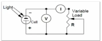
A dye-sensitized solar cell was assembled by sealing the dye-coated TiO2 electrode with the platinum-coated FTO counter electrode using a thermal plastic hot-melt sealant with a thickness of 50 µm leaving a small space for the electrolyte introduction. The electrolyte was then introduced into the space between the electrodes via the small space that was left during sealing, which was later sealed by already melted plastic hot-melt sealant. A second cell was sealed by simply placing the two electrodes together without the hot melt sealant. The electrolyte was then injected between the electrodes. The electrodes were then held together by two magnets, one on either side. The cells were kept in darkness for 24 hours to allow the electrolyte to dissolve before characterization. During characterization the cells were covered with a black-printed paper with a hole measuring 0.64 cm2 for the active area. The completed DSSC was illuminated with a 450 W halogen lamp placed 30 cm away and photovoltaic performance measured. The intensity of the lamp was 100 mW/cm2. The Voc and Isc were obtained by connecting the illuminated cell directly to the multimeter. The current density-voltage (J-V) characteristic curve was obtained by connecting the electrodes to a variable resistor as shown in the circuit below that was obtained from [22].
Figure 2: Experimental setup for measuring the current voltage characteristics of DSSC
The equations below obtained from [19] and J-V curve were used in calculating the fill factor and efficiency
(6)
Where the fill factor is given by;
Where ƞ is the energy conversion efficiency, PMAX is the maximum power produced by the cell, PIN is the power into
the cell, FF is the fill factor, VOC is the open circuit voltage, ISC is the short circuit current, IMAX is the current at the
maximum power and VMAX is the voltage at the maximum power.
IV. RESULTS AND DISCUSSION
The following graphs were obtained from the data collected by plotting current/power density against voltage as shown below:
Figure 3: A graph of power density /current density against voltage (a) cell without a magnet (b) Cell with a magnet.
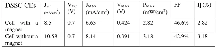
The cell without a magnet (figure 3 (a)) recorded an initial VOC=0.7 V, JSC = 10.58 mA/cm2, PMAX =3.18 mW/cm2,
VMAX = 0.391 V, JMAX = 8.14 mA/cm2, = 42.9%, FF= 3.18%. The cell with a magnet (figure 3 (b)) recorded its
initial values as follows: JSC=8.5 mA/cm2, VOC= 0.7 V, JMAX= 6.65 mA/cm2, VMAX = 0.434 V, PMAX = 2.82 mW/cm2, FF
= 46.6% and ƞ=2.82%. The JSC is slightly lower than the one for the cell without a magnet.
The Voc is a function of the semiconductor band gap and charge recombination in the cell which voltage generated
under illumination corresponds to the difference between the Fermi level of the electron in the solid and the redox potential of the electrolyte. JSC mainly depends on the light harvesting, eventual charge separation at the Dye/TiO2
interface and ambient temperature.
Table 1: The photovoltaic parameters of the DSSCS
The cell with a magnet as observed in figure 3 (b) had lower conversion efficiency due to the lower current density. When current flows in a conductor, there is a magnetic field built around it. If a magnet is brought near the conductor
DSSC CEs
JSC(mA/cm2)
VOC
(V)
JMAX
(mA/cm2
)
VMAX
(V)
PMAX
(mW/cm2
)
FF Ƞ (%)
Cell with a magnet
8.5 0.7 6.65 0.424 2.82 46.6% 2.82
Cell without a magnet
its magnetic field interacts with the field due to the conductor exerting a repulsive force on the current. Some work has to be done to overcome the force. As a result there is a reduction in the current flowing through the circuit. This explains why the cell with the magnet recorded a lower JSC and JMAX than the one with a magnet. The magnetic field
due to the Nd-Fe-B magnet interacted with the field due to the current in the circuit producing a repulsive force. Some current was used to do the work required to overcome the repulsive force, hence its low value. The magnet doesn’t have any effect on the open circuit voltage.
0 20 40 60 80 100 0 5 10 J SC (mA/ cm 2 )
# Days after fabrication
Cell with a magnet Cell without a magnet
(a)
0 20 40 60 80 100 0.0 0.1 0.2 0.3 0.4 0.5 0.6 0.7 0.8 O p e n ci rcu it vo lt a g e , Voc (v)
Days after fabrication
Cell without a magnet Cell with a magnet
(b)
Figure 4: (a) A graph of short circuit current against time and (b) a graph of open circuit voltage against time
As observed in figure 4 (a) the JSC for the cell with a magnet was initially at 8.65 mA/cm 2
which decreased with time and reached 2.37 mA/cm2 after 90 days. The short circuit current for a cell without a magnet also decreased from the initial 10.54 mA/cm2 and reached 0.01 mA/cm2 after 90 days. The open-circuit voltage for both cells was initially 0.7 V The voltage decreased with time reaching 0.03 V and 0.361 V for the cell without a magnet and the cell with a magnet respectively
.
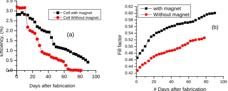
It can clearly be seen in figure 4 (b) that the open circuit voltage for the cell with a magnet a magnet reduced at a slower rate compared to the one without a magnet.The initial efficiencies were 2.82% and 3.18% for the cell with and without a magnet respectively. These values decreased with time with the cell without a magnet reaching almost zero at the 81st day as observed in figure 5 (a). The cell with a
magnet
was relatively stable recording an efficiency of 0.42% at the 90th day.0 20 40 60 80 100
0.0 0.5 1.0 1.5 2.0 2.5 3.0 3.5 E fficien cy, (% )
Days after fabrication
Cell with magnet Cell Without magnet
(a)
0 20 40 60 80 100
0.42 0.44 0.46 0.48 0.50 0.52 0.54 0.56 0.58 0.60 0.62 F ill f a ct o r
# Days after fabrication with magnet
Without magnet
(b)
The initial fill factors were 0.47% and 0.43% for the cell with and without a magnet respectively. The FF for the cell sealed with a magnet increased at a higher rate with time compared to the one without the magnet as shown in figure (b). The cell with a magnet showed a better photovoltaic performance with time. This could be due to the reduced rate of leakage. The magnet can therefore be termed to have reduced the rate of leakage. The FF of the two cells increased slightly with time, however this could be likely as a result of reduced resistive losses due to falling Isc and not
improvement of the photovoltaic performance.
IV. CONCLUSION
A comparative study was made on the I-V characteristics of a cell sealed with a magnet and another without a magnet over a period of 90 days. The initial JSC, JMAX and PMAX reduce considerably when a magnet is used
.
Findings of thisstudy indicate that the magnet does not have a significant effect on the initial VOC but it affects the JSC. The magnet
reduced the rate of electrolyte leakage
.
ACKNOWLEDGEMENT
I am so grateful to National Council of Science, Technology and Innovation, Kenya for their financial support.
REFERENCES
[1] Rho, W., Suh, J. S., Jeon, H., Kim, H., Jun, B. and Chun,g W., “Recent Progress in Dye-Sensitized Solar Cells for Improving Efficiency: TiO
Nanotube Arrays in Active Layer”, http://dx.doi.org/10.1155/2015/247689/ 20th August 2015
[2] Kwan, W. T., “ Commercialization Potential of Dye-sensitized Mesoscopic solar cells”, Master’s Thesis, Nanyang Technological University, Singapore ,2008
[3] Ziqi, S., Jung, H. K., Yue, Z., Fargol, B., Victor, M. and Shi, X. D., “ Improved photovoltaic performance of dye-sensitized solar cells with modified self-assembling highly ordered mesoporous TiO2 photoanodes”, Journal of Materials Chemistry, Vol. 22, issue 1, pp. 11711-11719, 2012.
[4] Hamann, T. W., Jensen, A. R., Martinson, F. B. A. and Hupp T. J., “Advancing beyond current generation dye-sensitized solar cell”, The Royal
Society of Chemistry, Vol.1, pp.66-78, 2008.
[5] Grätzel, M. and O’Regan, B., “A Low-Cost, High-Efficiency Solar Cell Based on Dye- sensitized Colloidal TiO2 Films”, Nature, Vol.353, pp. 737-740, 1991.
[6] Grätzel, M., “Photoelectrochemical Cells,” Nature, Vol. 414, pp. 338-344, 2001
[7] Chung, I., Byunghong, L., Jiaqing, H., Robert, P. H. C. and Mercouri, G. K., “All-solid-state dye-sensitized solar cells with high efficiency”, Nature, Vol. 485, pp. 486-487, 2012.
[8] Rho, W., Suh, J. S., Jeon, H., Kim, H., Jun, B. and Chung, W., “Recent Progress in Dye-Sensitized Solar Cells for ImprovingEfficiency: TiO
Nanotube Arrays in Active Layer”, http://dx.doi.org/10.1155/2015/247689/ 20th August 2015
[9] Khan, M. M. S., Khan, M. A., Mohammed, M. A., Sultana, S., Islam, M. M. J. and Uddin, J., “Sensitization of Nanocrystalline Titanium dioxide Cells using Natural dyes: influence of acids medium on coating formulation”, American academic and scholarly journal ,Vol 4, no. 5, 2012
[10] Khan I. M., “A study on the optimization of dye-sensitized solar cells”, Graduate thesis and dissertations, University of South Florida, 2013. [11] Haiying, W., “Dye Sensitized Solar Cells.” http://bama.ua.edu/chem/seminars/students-seminars/fall04/papersf04 20th August 2015. [12] Hardin, E. B., “ The dye sensitized solar cells”, In:Behind the scenes of Sunny memories, Swissnex San Fransisco, 21 April, 2010. [13] Karami, A., “Synthesis of TiO Nano Powder by the Sol-Gel Method and Its Use as a
[14] Photocatalyst”, Journal of Iranian chemical society, Vol. 7, pp. S154-S160, 2010.
[15] Gratzel, M. & Hagfeldt, A., “Molecular Photovoltaics”, Accounts of chemical research, Vol. 33, pp. 269-277, 2000.
[16] Baxter, J.B; Walker, A.M; Van, O. K. & Aydil, E.S., “Synthesis and characterization of ZnO nanowires and their integration into dye-sensitized solar cells”, Nanotechnology, Vol. 17, Issue 11, pp. S 304-S 312, 2006.
[17] Boercker, J.E; Schmidt, J.B. & Aydil, E.S., “Transport Limited Growth of Zinc Oxide Nanowires”, Crystal Growth, Vol. 9, pp 2783–2789, 2009.
[18] Law, M., Greene, L. E., Johnson, J. C., Saykally, R. & Yang, P. D., “Nanowire dye sensitized solar cells”, Nature Materials, Vol. 4, pp. 455-459, 2005.
[19] Nazerruddin, M.K., Kay, A., Ridicio, I., Humphry-Baker, R., Mueller, E., Liska, P., Vlachopoulos, N. & Gratzel, M., “Conversion of light to electricity by cis-X2bis(2,2'-bipyridyl4,4'-dicarboxylate)ruthenium(II)charge-transfer sensitizers (X = Cl-, Br-, I-, CN-, and SCN-) on nanocrystallinetitanium dioxide electrodes”, Journal of American Chemical Society Vol. 115, pp. 6382-6390, 1993.
[20] Gratzel M. (2003). “Dye-sensitized solar cells”, Journal of photochemistry and photobiology C: Photochemistry reviews, Vol.4, pp. 145-153,
2003.
[21] Roh, D. K., Chi W. S. and Jeon, H., “High Efficiency Solid-State Dye-Sensitized Solar Cells Assembled with Hierarchical Anatase Pine
[22] Bard, A. J. and Faulkner, L. R., “Electrochemical Methods, Fundamentals and Applications”, second edition; John Wiley and Sons: New York, p 316, 2000
![Figure 1: The structure of solar cell [12]](https://thumb-us.123doks.com/thumbv2/123dok_us/1657800.1207919/2.595.129.468.405.567/figure-structure-solar-cell.webp)