Volume 2011, Article ID 530354,20pages doi:10.1155/2011/530354
Research Article
Securing Embedded Smart Cameras with Trusted Computing
Thomas Winkler and Bernhard Rinner
Pervasive Computing Group, Institute of Networked and Embedded Systems, Klagenfurt University, Lakeside Park B02b, 9020 Klagenfurt, Austria
Correspondence should be addressed to Thomas Winkler,[email protected]
Received 31 May 2010; Accepted 19 August 2010
Academic Editor: Damien Sauveron
Copyright © 2011 T. Winkler and B. Rinner. This is an open access article distributed under the Creative Commons Attribution License, which permits unrestricted use, distribution, and reproduction in any medium, provided the original work is properly cited.
Camera systems are used in many applications including video surveillance for crime prevention and investigation, traffic monitoring on highways or building monitoring and automation. With the shift from analog towards digital systems, the capabilities of cameras are constantly increasing. Today’s smart camera systems come with considerable computing power, large memory, and wired or wireless communication interfaces. With onboard image processing and analysis capabilities, cameras not only open new possibilities but also raise new challenges. Often overlooked are potential security issues of the camera system. The increasing amount of software running on the cameras turns them into attractive targets for attackers. Therefore, the protection of camera devices and delivered data is of critical importance. In this work we present an embedded camera prototype that uses Trusted Computing to provide security guarantees for streamed videos. With a hardware-based security solution, we ensure integrity, authenticity, and confidentiality of videos. Furthermore, we incorporate image timestamping, detection of platform reboots, and reporting of the system status. This work is not limited to theoretical considerations but also describes the implementation of a prototype system. Extensive evaluation results illustrate the practical feasibility of the approach.
1. Introduction and Motivation
Video cameras are present in many parts of our daily lives. In surveillance applications they are used to monitor train stations, airports, or public places in cities [1]. Enforcement applications and traffic monitoring [2] are another applica-tion area where camera systems are frequently used. In all those applications multiple, spatially distributed cameras are used to cover large areas. But the deployment of cameras is no longer limited to public places. An example where cameras are installed in private environments is assisted living. Elderly people are monitored in their homes to detect unusual behavior such as the collapse of persons [3].
Technologically, camera systems have evolved from ana-log to fully digital and sometimes even smart systems. Modern cameras not only deliver videos in digital form, but are also capable of on-board processing and analysis of captured images. Together with increasing computing power, the amount of software running on cameras is also growing. Nowadays, many smart cameras are equipped with powerful embedded operating systems such as uClinux. These systems
come with a variety of libraries and many applications and system services. The emerging field of visual sensor networks
[4] aims to miniaturize cameras and turn them into truly
pervasive sensors [5]. As part of these efforts, many cameras no longer use wired network connectivity but come with wireless interfaces which eases deployment significantly. It is expected that the wireless interfaces and the relatively large software stack will make smart cameras an attractive target for attackers. Considering the sensitivity of video data, appropriate countermeasures must be taken to provide security guarantees for information that is coming from a camera.
networks is meaningless without taking a holistic approach towards securing the entire camera device. To fill this gap, we apply Trusted Computing (TC) techniques and a dedicated microchip called Trusted Platform Module (TPM). Being a hardware-based security solution, TC is designed to achieve higher security than pure software solutions could do. Furthermore, TPMs are cheap, readily available, and implement a set of well defined and widely reviewed security primitives. Alternatives to TC would be hardware security solutions like ARM TrustZone or TI M-Shield which are integrated into several embedded processor systems. The disadvantage of these solutions is that they are proprietary and only little documentation is publicly available.
To our knowledge, this is the first work that applies and evaluates TC in embedded smart camera networks. A major challenge is the proper integration into a camera system and its computer vision task without considerably reducing overall system performance. In our previous work [9–11], we addressed the integrity, authenticity, and confidentiality of video data. This paper is based on our previous results and extends them in several ways. We contribute to the state of the art in at least the following three areas. (1) We discuss the
establishment of the chain of trust on our TrustCAM [10]
prototype. We evaluate the performance impact on system boot and discuss the resource tradeoff for different root of trust implementations. (2) We describe a timestamping mechanism for frame groups that ensures data freshness, guarantees correct frame order, and allows us to associate a world time interval with each frame. (3) Reboots of the camera system and the current system status are reliably reported with a periodic lifebeat.
The remainder of this paper is organized as follows.
Section 2discusses the goals and the underlying assumptions for our work. Since we base our work on Trusted Computing,
Section 3presents an overview of the fundamental concepts
of this technology. Thereafter, in Section 4 we present
our system architecture including our TrustCAM prototype platform. In Section 5 we discuss different aspects of the integration of TC into a camera system. This includes the establishment of a chain of trust, a trusted lifebeat as well as image encryption, signing, and timestamping. Implementation details and evaluation results are presented in Section 6. In Section 7, we summarize related work on security in camera systems and applications of Trusted Computing in embedded systems. Finally, we outline future work and conclude the article inSection 8.
2. Goals and Assumptions
The primary focus of this work lies on enhancing the security of an embedded smart camera system to provide certain guarantees for the delivered video and image data. This section outlines the goals and the assumptions we made.
2.1. Goals. For the design of our TrustCAM prototype
system, we define the following goals.
Camera Status Monitoring. Since cameras are often
installed in remote locations that are not under full
control of the operators, a mechanism is required that allows one to reliably check the current status of a camera. This should include a report about the executed software as well as the detection of unscheduled system reboots.
Authenticity of Videos.In many applications such as
traffic monitoring and law enforcement, the origin
of information is important. In visual surveillance, this is equivalent to knowing which camera captured a video stream. This can be achieved by explicitly authenticating the cameras of a network and embed-ding this information into the video streams.
Freshness of Videos.To prevent replay attacks where
recorded videos are injected into the network to replace the live video stream, freshness of image data must be guaranteed. Even more, in many areas including enforcement applications, evidence is required when a video sequence was recorded. Applying timestamps to images delivered by a camera is a way to satisfy both of these requirements.
Integrity of Videos.Image data coming from a camera
can be intentionally modified by an attacker during transmission or when stored in a database. Using checksums and digital signatures, data integrity can be ensured. An often overlooked issue is that integrity protection is not only important for single frames but also for sequences. Simple reordering of images can substantially change the meaning of a video.
Confidentiality of Videos. It must be assured that no
third party can eavesdrop on sensitive information that is sent from the cameras to the control station. Confidentiality must not only be provided for image and video data transmitted over the network but also for videos that, for example, are stored on a camera to be transmitted at a later point in time.
Limited Access to Videos.Access to confidential video
data must be limited to persons with adequate security clearance. For highly sensitive data, multiple system operators should be required to cooperate to reveal the data.
2.2. Assumptions and Scope. This work primarily deals with
security issues related to the embedded camera system itself and video data delivered by it. We therefore make several assumptions about other aspects and system components.
Centralized Control. In our concept, cameras are
this is done in the same format as they are delivered by the camera. Integrity and authenticity information as well as timestamps are not removed from the stream and confidential video data is not decrypted before being stored. This ensures that sensitive data is not only protected during transmission but also when archived.
Networking.We assume that all cameras that belong
to the network can be accessed in one or more hops over a wireless connection. In a larger deployment, topology control and clustering would be required to ensure scalability. Moreover, we do not address network security issues including secure routing or the secure formation of camera clusters.
Physical Attacks. Our main concern are software
attacks on the cameras and the delivered data. Attacks on camera hardware, including hardware manipula-tion as well as power and timing analysis [12] are beyond the scope of this work. We however assume that, for example, with specifically designed camera enclosures and circuit boards, a reasonable degree of resistance against tampering can be achieved. If a hardware attack involves the reboot of the camera, this should be detectable for camera operators.
Availability. In some cases, camera systems are
considered as critical infrastructure and therefore guarantees about the availability of system services should be provided. Specifically, this also includes resistance against denial of service attacks. This would require to monitor and control resource usage and to validate incoming requests regarding, for example, their authenticity, integrity, and freshness. This is currently not addressed in our approach. Moreover, providing service and availability guar-antees is inherently difficult when using a wireless communication channel that is easily jammed.
3. Trusted Computing Overview
Trusted Computing (TC) [13, 14] is an industry initiative
headed by the Trusted Computing Group (TCG) [15]. The
main output of the group is a set of specifications for a
hardware chip—the Trusted Platform Module (TPM) [16]—
and surrounding software infrastructure such as the TCG Software Stack (TSS) [17]. The TPM, as shown inFigure 1, is a purely passive device that cannot actively interfere with the boot process of the host system or prevent the execution of software. Internally, a TPM typically is implemented as a microcontroller (execution engine) with accelerators for RSA and SHA1. Additionally, the TPM provides a random number generator (RNG) as well as limited amount of volatile and non-volatile memory. With an opt-in procedure, users can choose if they want to make use of the TPM chip. Each TPM is uniquely identified via a special RSA key called
Endorsement Key(EK). This EK is created either by the TPM
manufacturer as part of the fabrication process or by the
Host system
RSA engine RNG I/O Non-volatilememory RSA key
generation
SHA 1 Opt-In Executionengine memoryVolatile
TPM
Figure1: A Trusted Platform Module (TPM) consists of shielded locations (memory) and protected capabilities which are functions that operate on shielded locations.
user when taking ownership of the TPM. Either way, the EK cannot be changed or removed throughout the entire lifetime of the TPM.
RSA keys can be generated for different purposes such
as data encryption or signing. Upon creation, keys can be declared migratable or not. While migratable keys can be transferred to a different TPM, non-migratable keys cannot. A password called usage secret can be specified upon key creation. If specified, this password has to be provided every time the key is used. Likewise, a migration secret can be specified that must be supplied if the key is to be migrated to another TPM. Regardless of key type and migratability, a private TPM key can never be extracted from the chip as plain text but only in encrypted form. By definition, every key is required to have a parent key that is used to encrypt the private key when it has to be swapped out of the TPM due to limited internal memory. At the root of this key hierarchy is
theStorage Root Key(SRK) which never leaves the TPM.
Aside from basic cryptographic functionality, TC and the TPM provide the following threeroots of trust.
Root of Trust for Measurement (RTM). In TC,
measuring is the process of computing the SHA1 hash of an application binary before it is executed. Since the TPM is a purely passive device, it cannot initiate measurements or interfere with the system boot process. Another trusted building block is required to perform the initial measurement. On a PC system, this typically is an immutable part of the BIOS which measures the next software component before it passes control to it. Assuming that all subsequent components proceed the same way, a
sequence of measurements—called chain of trust—
amount of memory inside the TPM is limited, a special operation called TPM Extend is used when writing to PCRs:
PCR[i]←−SHA1(PCR[i]measurement). (1)
With the TPM Extend operation, the current PCR value is not overwritten but the new measurement is accumulated with the current PCR value. PCRs are only reset upon platform reboot. Using only the accu-mulated PCR values, it is difficult to assert the state of a system. For a verifier, the individual measurements representing the software components executed on the system might be of greater interest. To facilitate that, the TCG measurement concepts propose the use of a PCR log that is stored outside the TPM. This log contains one entry for each measurement that was extended into a PCR. Using these log entries, a verifier can reproduce the current PCR values step by step and thereby get knowledge about the executed software components. Note that even though the log is stored outside the TPM, any manipulation can be easily detected since the reproduced PCR values would not match those securely stored inside the TPM.
Root of Trust for Reporting (RTR). Reporting of the
state of a platform is called attestationand is done with the TPM Quote command. As part of that, PCR values are signed inside the TPM using a key unique to that TPM. In theory, this key could be the EK of the TPM. In practice this is not done due to privacy reasons. If the EKs were always used for signing the PCRs, all these signatures could be tracked to a single TPM and hence a group of persons that use the machine with this TPM for several different purposes. Consequently, not directly the EK but alias keys are used to sign the PCRs. They are called
Attestation Identity Keys (AIKs) and are generated
with the help of an external trusted third party called
PrivacyCA. Details on AIK creation can be found,
for example, in work by Pirker et al. [19]. With
version 1.2 of the TPM specification an additional mechanism was added to create AIKs. It is called Direct Anonymous Attestation (DAA) and is based on group signatures.
Root of Trust for Storage (RTS). The RTS allows one to
use the TPM to securely store data. Binding of data refers to encrypting data with a TPM key and hence guaranteeing that the data only is accessible by this specific TPM instance. Sealing of data allows one to specify a set of PCR values the data is sealed to. As with binding, the unsealing can only be done by the specific TPM instance that holds the private sealing key. Additionally, the plain text is only released if the current PCR values match those specified upon sealing.
Functionality that was added to the TPM specification in version 1.2 is timestamping and non-volatile (NV) storage inside the TPM which can be used for custom applications. One usage of the NV storage is for certificates shipped by the TPM or platform manufacturers. The remaining available space can be used for custom applications. Access to NV storage can be defined to require authorization or be limited to a certain platform state represented by a set of PCR values. Timestamping is an important functionality in many applications. For simplicity and cost reasons, the TPM does not contain a realtime clock. Instead, a tick counter is included that is reset to zero upon system bootup. The TPM specification recommends that the tick counter value TCV is incremented at least every millisecond. The actual increment rate is vendor specific and can be queried from the TPM as the tick rate TRATE. To be able to distinguish different tick counter sessions resulting from platform reboots, a random tick session nonce TSN is generated every time the TCV is reset. Associating the (TSN, TCV) pairs with world time is left to the application.
4. System Architecture
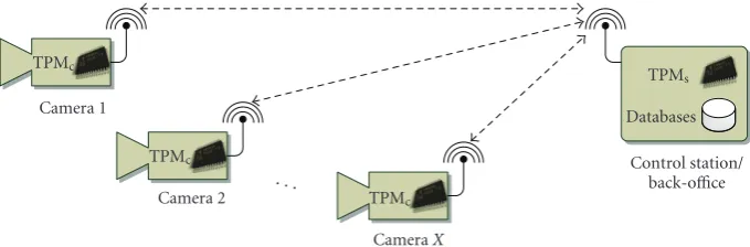
In our visual sensor network architecture, cameras are assumed to be spatially distributed to cover a large area. Network connectivity is provided by wireless communica-tion technologies. Cameras are controlled and operated from a central facility subsequently called Control Station (CS). Each camera can be reached from the CS in one or more hops. As described inSection 2, we assume that the CS is a secure and trustworthy facility.
Figure 2 shows a network of X camera nodes and one central control station. Every camera is equipped with a TPM chip called TPMC. Likewise, the computing infrastructure of
the CS contains a TPM subsequently referred to as TPMS.
In addition to TPMS, the CS also hosts a database where
cryptographic keys generated during camera setup, and data received from the cameras as part of periodic lifebeats, are stored. Moreover, we assume that the CS has a reliable and accurate time source which is required to associate lifebeat events and timestamps with world time.
4.1. Camera Setup and Deployment. Before a camera is
deployed, it has to be set up. It is assumed that this setup is done when the camera is under full control of the operating personnel. The main part of the setup involves the generation of TPM keys on the camera and at the control station. All keys are generated as 2048 bit RSA keys. The following setup steps and the key generation are done for every camera of the network.
TPM Ownership. Calling the TPM TakeOwnership
operation of the cameras TPMCsets an owner secret
and generates the Storage Root KeyKSRK. The owner
TPMc
Camera 1
TPMc
Camera 2 . . . TPMc
CameraX
TPMs
Databases Control station/
back-office
Figure2: A network of TPM-equipped cameras managed by a central control station.
Identity Key Creation. An Attestation Identity Key
serves as an alias for the Endorsement Key (KEK) and
is used during platform attestation. Contrary to a conventional PC, there are not multiple human users on a smart camera. The system software running on the camera takes the role of a single system user. Moreover, all cameras in the network are uniquely identified and well known by the operators. Consequently, there is no need for the anonymity gained by using multiple AIKs in conjunction with a PrivacyCA. Therefore, only a single Attestation Iden-tity KeyKAIKis generated during setup that serves for
platform attestation. The public partKAIKpubis stored
in the CS database together withKEKpub.
Signature Key Creation. For signing data such as
events or images delivered by a camera, a nonmi-gratable singing keyKSIGis created withKSRK as its
parent. Being non-migratable ensures that the private key cannot leave the camera’s TPMC. This provides
assurance that data signed with this particular key really originates from this specific camera.
Binding Key Creation. To ensure confidentiality of
sensitive data, images sent by the camera to the CS have to be encrypted. This encryption can be done for full images or special regions of interest where, for example, motion or faces have been detected.
To ensure confidentiality, at least one non-migratable binding keyKBIND 1is created by the control station’s TPMS.
The public part of this key,KBIND 1pub, is exported from TPMS
and stored on the camera. Note that the private part of
KBIND 1cannot be exported from TPMS and therefore data
encrypted with KBIND 1pub can only be decrypted at the CS
and not by an intermediate attacker who interferes with the transmission. To decrypt data bound with KBIND 1pub, the
usage secret of the key has to be supplied by the system operator. To avoid that a single operator who has access to the control station and knowledge of this usage secret can decrypt data, additional binding keysKBIND 2toKBIND Ncan
be generated. Privacy sensitive data can then be encrypted with multiple binding keys. Assuming that no single operator knows all the usage secrets for the binding keys, two or more operators have to cooperate to decrypt the data. The
Nbinding keys can also be used to realize different security
Table 1: The cryptographic keys generated during setup of a single camera. TheControl StationandCameracolumns denote the storage location of the keys. Binding keys are generated by TPMS while all other keys are generated by TPMC. All keys are non-migratable, 2048 bit RSA keys. Thepubsubscript denotes the public RSA key.
Control Station Camera
Endorsement Key KEKpub KEK
Storage Root Key — KSRK
Attestation Identity Key KAIKpub KAIK
Signature Key KSIGpub KSIG
Binding Keys KBIND 1 KBIND 1pub
KBIND 2 KBIND 2pub
..
. ...
KBIND N KBIND Npub
levels. Data at different abstraction levels (e.g., full images versus images where people’s faces have been removed versus textual event descriptions) can be encrypted with different binding keys. Depending on security clearance, only certain abstraction levels can be accessed by an operator.
Table 1summarizes the cryptographic keys generated as part of the camera setup procedure.
4.2. Key Management Considerations. Regarding key
man-agement, our primary assumption is that keys are distributed during setup where the system is under full control of the operating personnel. The proposed system currently sup-ports no mechanisms for key distribution during runtime. Considering our application domain we believe that this is a reasonable assumption. Cameras of a visual surveillance network are intentionally placed and installed by experts. In such a relatively static environment there is little need for dynamic key exchange.
Aside from distribution, the management of keys needs to be considered in case a component of the system has to be upgraded or exchanged. Our concept proposes to use only non-migratable TPM keys which means that private keys cannot be transferred to another TPM. For the cameras this is clearly a desirable property since it ensures that data signed
with the TPM keyKSIGactually comes from the camera the
TPM is part of. In cases where a camera is replaced, we do not see any need to migrateKSIGfrom the old to the new camera.
Instead, a newKSIG is created for the new camera. The key
of the old camera however should be deleted by clearing the TPM to ensure that it cannot be used after the camera has been taken out of service.
For the control station the situation is different. All
data that was encrypted by the X cameras of the network
with their public binding keys KBIND 1pub to KBIND Npub is
lost if the hardware infrastructure of the control station is
upgraded and this upgrade also includes TPMS. To allow
such maintenance, the binding keysKBIND 1pub toKBIND Npub
could be made migratable. This would allow to transfer the binding keys to the updated control station hardware. Key migration can only be performed if the migration password specified upon key creation is supplied. Clearly, it is critical that appropriate policies for management of these migration secrets are applied. These policies must also ensure that the old TPMSis properly cleared and all its keys are invalidated.
The public binding keys KBIND 1pub to KBIND Npub
gen-erated by TPMS have to be stored on the camera. Since
they are public, no special protection is required because all an attacker can do with these keys is to encrypt data that only can be decrypted at the control station. The question remains where to store these keys on the camera. If the keys have to be placed in the camera’s file system, this means that the file system has to be specific for every deployed camera. To avoid this, we make use of the non-volatile storage of TPMCto store the public binding keysKBIND 1pub
toKBIND Npub. Additionally, the NV space can be used to store
small amounts of camera-specific configuration data. Access to the NV space with the binding keys and configuration data can be limited to a specific system configuration.
4.3. TrustCAM Hard- and Software Prototype. Our custom
TrustCAM prototype system is largely built from commer-cially available components. TrustCAM is based on the Bea-gleBoard [20] which has a dual-core processor with an ARM Cortex A8 CPU clocked at 480 MHz and a TMS320C64x+ digital signal processor running at 360 MHz. The system is equipped with 256 MB RAM and 256 MB NAND flash. Via USB, we connect a color SVGA CMOS sensor (Logitech QuickCam Pro 9000) and an RA-Link RA-2571 802.11b/g WiFi adapter. An XBee radio provides a second, low-performance communication channel. Finally, an Atmel AT97SC3203S—the only commercial TPM designed for embedded devices—is connected to the mainboard via the I2C bus.Figure 3shows a picture of the prototype system.
As operating system we use an ARM Linux system together with a customized, OMAP-specific kernel. For TPM
access, we use a modified version of the TrouSerS [21]
Figure3: The TrustCAM prototype with the image sensor, the XBee radio, and the Atmel I2C TPM at the top level. Behind that are the processing board and WiFi radio.
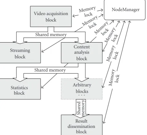
TCG software stack where we have replaced the trusted device driver library (TDDL). Our fully custom TDDL implementation manages access to the TPM via the I2C bus. To simplify application development and to allow reuse of components, we designed a software framework that supports composition of applications from individual blocks which are instantiated and interconnected. This approach follows the concept of modeling the dataflow between the individual components. Conceptually, every block has an output memory where its results can be accessed by subsequent blocks. To maintain consistency of stored data, access to shared memory is guarded by a lock that is passed between the producing and consuming block. Blocks can form chains of arbitrary length where each pair of blocks is connected by shared memory and a lock. In our implementation, a processing block is realized as an individual process expecting well-defined input data and generating output consumable by subsequent blocks. The shared memories are implemented as POSIX shared memory synchronized by an interprocess locking mechanism.
the locks that guard the shared memory regions. Additional details and performance evaluations for the camera software framework are provided in [22].
5. Trusted Computing Integration
The lifecycle of a smart camera starts with its setup and
deployment which we described in Section 4.1. When the
camera boots, the chain of trust has to be established starting at a root of trust for measurement. In the following
Section 5.1, we present the realization of this boot procedure for our TrustCAM prototype system. Once the system is booted, the computer vision tasks are executed. To check the status of the system and to detect unscheduled system reboots, the control station sends a periodic lifebeat request which is described in Section 5.2. If the control station requests a video stream from the camera, data integrity, authenticity, and freshness must be ensured. This is dis-cussed in Section 5.3. Considering the sensitivity of video data, also the confidentiality of images must be preserved. Our approach to achieve this, is described in Section 5.4. Additionally, we demonstrate the realization of two security levels.
5.1. Trusted Boot and Chain of Trust. As described in
Section 3, on PC systems the Root of Trust for Measurement (RTM) is typically implemented as an immutable part of the BIOS. Recent CPUs and chipsets from AMD and Intel provide an instruction set extension that allows one to establish a chain of trust after the system has already booted. This is achieved via a so-called dynamic root of trust. Since both of these mechanisms are not available on today’s embedded systems, we discuss how the chain of trust can be established on an existing embedded device. Our approach is based on the concepts of a static RTM.
The OMAP 3530 CPU of our system uses a multistage boot process [23]. On power-up, the system executes the first bootloader stage located in an internal 32 kB ROM. After performing basic hardware configuration, the ROM code creates a list of boot devices. This list is based on six hardware
pins of the CPU calledSYS BOOTpins. Upon board design,
a certain boot sequence can be defined by hardwiring these pins accordingly. By default, the BeagleBoard boot order is NAND, USB, UART 3, and MMC. With only minor modifications of the board design, this boot sequence can be hardwired to, for example, always boot from UART 3.
After the ROM code has prepared the boot device list
based on theSYS BOOT pins, the next bootloader stage is
copied into SRAM. This second bootloader stage is called X-Loader and it has to be small enough to fit into the 64 kB of the SRAM. The X-Loader then initializes additional peripherals including the SDRAM controller and then loads the Boot bootloader as the third stage into SDRAM. U-Boot finally loads and executes the Linux kernel.Figure 5(a)
gives an overview of this default OMAP boot procedure. To integrate the TPM into the boot process and establish the chain of trust, modifications to the system are required. Ideally, the internal ROM of the OMAP should measure the
second bootloader stage (X-Loader) and extend it into one of the PCRs (Figure 5(b)). To be able to measure X-Loader, code for the SHA1 hash algorithm needs to be integrated into the ROM code. This however can be avoided if the SHA1 engine of the TPM is used. This keeps modifications of the ROM code at a minimum and should allow to integrate the RTM functionality into the ROM code without exceeding the 32 kB ROM size. The downside of this approach is that measuring of X-Loader would take significantly longer com-pared to a software SHA1 implementation running on the OMAP CPU. This is primarily due to the low performance of the TPM and the relatively slow I2C communication. InSection 6.3we provide comparison measurements and a discussion of the performance of the two approaches. Note that the “ideal” integration of an RTM into our TrustCAM prototype—or any other OMAP-based embedded system— would require the cooperation of the CPU manufacturer to integrate the TPM-enabled ROM code during production.
For the implementation of an RTM for the TrustCAM
prototype we therefore chose a different approach that is
shown in Figure 5(c). The SYS BOOT pins of the OMAP
allow to force the ROM code to request the second boot-loader stage from UART 3 as a first boot device. This pin configuration can easily be hardwired in a custom PCB design. In our design we use a trusted building block which is connected to the OMAP’s UART 3 and answers the download request. This could be a one-time programmable memory together with minimal, additional logic. For our proto-type, we realized this component with a microcontroller that downloads the second stage (X-Loader) bootloader. Once X-Loader has been downloaded, the application on the microcontroller terminates and no further interaction between the OMAP CPU and the microcontroller is possible until the next reboot of the system. Allowing no further communication between the two systems is important since it ensures that a potential attacker who gains access to the system that runs on the OMAP CPU, cannot access or modify the X-Loader located on the microcontroller. Compared to modifying the ROM code, our prototype approach provides no resistance against hardware attacks. With full physical access to a camera, it is easy to change the boot procedure and prevent the correct establishment of the chain of trust. As stated inSection 2, hardware attacks are not in the focus of our current work. We nevertheless believe that the proposed mechanism to establish the RTM can still be valuable for legacy devices especially when combined with the Trusted Lifebeat described in Section 5.2. Hardware attacks often cannot be performed on a running system or require a reboot to become effective. The lifebeat allows operators to detect such unexpected events and initiate further actions like retrieval and inspection of the camera.
Video acquisition block Shared memory Streaming
block
Statistics block
Shared memory
Content analysis block
Arbitrary blocks
· · ·
Result dissemination
block
NodeManager
Shar
ed
memor
y
Memo ry
lock
Mem
ory lock Me
mor y
lock
Me mo
ry
lock
Me mo
ry
lock
Memory
lock
Figure4: TheNodeManageris responsible for creation of processing chains and management of inter-process communication. The output of individual blocks is stored in shared memory that can be accessed by one or more consumers.
Table 2: TrustCAM PCR usage. Each of the PCRs 1 to 5 only stores the measurement of a single software component. PCR 6 contains the accumulated measurements of the computer vision blocks started by the NodeManager.
PCR Measurement Measured by
1 X-Loader OMAP ROM code (ideal model only)
2 U-Boot X-Loader
3 Linux Kernel U-Boot
4 Kernel Parameters U-Boot
5 Root Filesystem U-Boot
6 vision processing blocks NodeManager
U-Boot measures the Linux kernel (PCR 3), its parameters (PCR 4), and the compressed root filesystem (PCR 5). Once control is passed to Linux, the root filesystem is mounted read-only and system startup continues. Note that contrary to a PC system, it is feasible to measure the entire root file system at once since typical sizes range from a few to a few dozens of MB. Keeping the number of measurements small, considerably simplifies verification of the system state. A verifier can easily check the overall status without complex evaluations of PCR logs. To be able to attest which computer vision applications actually are executed, we extend the
NodeManager introduced inSection 4.3. Being responsible
for starting the computer vision processing blocks, the NodeManager measures the configuration script and every block into PCR 6 before they are started. For typical scenarios, a processing chain is expected to be composed of no more than ten processing blocks. This keeps the number of measurements in PCR 6 relatively small. A log of the individual values that are extended into PCR 6 is kept on a partition separate from the root filesystem.
The full chain of trust of the TrustCAM prototype, including the measurements done by the NodeManager, is shown in Figure 5(c). By measuring the vision block separately from the root filesystem, a verifier cannot only get general information about the system firmware but also gain insight which image processing tasks are executed by the camera.
Table 2summarizes PCR usage of the TrustCAM prototype.
5.2. Trusted Lifebeat. The main purpose of a lifebeat is
to determine the state of a system based on the periodic transmission of status messages. If a status message is not received for a predefined amount of time, then it can be concluded that the system is no longer operational. The proposed trusted lifebeat mechanism extends this basic concept by supporting the following properties.
Platform Attestation. Based on TC attestation
tech-niques, the status of the platform is reported to the system operator. This not only allows one to reliably check which firmware is running on a camera but also which computer vision applications are executed. This is especially important if the NodeManager is capable of reconfiguring the system dynamically at runtime.
Reboot Detection. It is important to reliably detect
unintended reboots of a system as these are often an indicator for attacks. The trusted lifebeat allows one to securely detect and report reboots of a camera system. If such a reboot is detected, the camera should be retrieved for inspection.
World Time Mapping. We use the internal tick counter
Root filesystem
(b) Ideal boot sequence with TPM-enabled ROM code that measures the first stage of the bootloader and extends it into the TPM
NodeManger
(c) TrustCAM prototype boot procedure using UART booting to load X-Loader from a microcontroller that acts as trusted building block
Figure5: The boot procedures of the unmodified BeagleBoard, a TPM-enabled ideal system, and the TrustCAM prototype. Hardware components are drawn as gray boxes. Dashed lines represent the measuring of software components and extending these measurements into the TPM’s PCRs. This is always done before the next component is executed.
that purpose, the tick counter has to be associated with world time. The trusted lifebeat is used to realize this mapping of tick counter values to world time.
Contrary to a conventional lifebeat, in our architecture the lifebeat is not automatically sent by a camera but is periodically requested by the control station. This is done to supply a randomly generated nonce to ensure freshness of the platform attestation information contained in the lifebeat. The lifebeat response not only includes the attestation result but also the current TPM tick counter value (TCV), the tick session nonce (TSN), and the tick rate (TRATE). In detail, the trusted lifebeat protocol works as follows.
(1) The control station sends a random noncenand the
list of requested PCRs to a camera. Additionally, the control station records the current UTC timet0.
If the camera does not respond within a predefined amount of time, it is considered to be out of service and should be retrieved for inspection.
(2) The camera performs a TPM TickStampBlob opera-tion resulting in:
TickStampRes=TPMTickStampBlobKSIG(n
TSNLBTCVLBTRATELB).
(2)
TCVLBis the current tick value, TSNLBidentifies the
tick session with a unique nonce, and TRATELBis the
number of microseconds per tick.
(3) Then, the camera performs a TPM Quote operation and generates that
QuoteRes=TPM QuoteKAIK
PCRs
TickStampRes.
Note that TickStampRes is included in the signature instead of the noncensupplied by the control station.
n however is implicitly included as it is part of
TickStampRes. Including TickStampResassociates tick count and platform state. This provides the verifier with information about the platform state at the time the TickStamp operation was performed.
(4) QuoteRes, TickStampRes, the requested PCR values,
the timer values (TCVLB, TSNLB, TRATELB), and the
stored measurement log for the processing blocks started by the NodeManager are returned to the control station.
(5) When the response from the camera is received, the control station stores the current UTC time ast1.
(6) The control station verifies the provided data as follows:
(a) Retrieve KSIGpub of the intended camera from
the CS database and verify the signature of TickStampRes,
VerifyKSIGpubTickStampRes,
n, TCVLB, TSNLB, TRATELB
.
(4)
If the signature verification succeeds and the contained nonce matches the supplied nonce
n, one has assurance that the tick values are authentic, unmodified, and fresh.
(b) If TSNLB and TSNLB−1 are not identical, this
means that the camera was rebooted and the TPM has been reset since the last lifebeat event. If this reboot was not intentionally triggered by a system operator, it might be an indication for an attack on the camera. In such a case, the camera should be retrieved for inspection. (c) Verify the signature of QuoteRes using KAIKpub
from the CS database. If verification succeeds, one knows that the provided system state infor-mation is authentic and unmodified. Freshness of the attestation data is ensured implicitly via noncenincluded in TickStampRes.
(d) Check the returned PCR values for the boot-loader(s), the kernel, and the root filesystem against “known good“ values stored in the CS database. Evaluate the PCR values that represents the processing blocks started by the NodeManager together with the supplied PCR log. Checks include if all processing blocks, for example, are known and categorized as uncriti-cal. Due to the limited number of PCR values that need to be evaluated, the overall system status verification is considerably simplified compared to a general purpose PC system.
(7) If any of the aforementioned checks fail, the camera should be taken out of service and retrieved for inspection.
(8) The time valuest0andt1and the tick counter values
TCVLB, TSNLB, and TRATELB are stored as a single
record in the database of the CS. This associates the tick value TCVLBof the tick session TSNLBwith the
UTC time intervalt0tot1.
The described, remotely triggered trusted lifebeat proce-dure does not necessarily have to be executed at a fixed time interval but the control station can send requests at random intervals. It however should be ensured that these intervals do not exceed a previously configured maximum time.
5.3. Image Signing and Timestamping. In applications such
as law enforcement or traffic monitoring, it is important to provide evidence where (i.e., by which camera) and when an image was taken. Having TPMs on the cameras provides basic functionality required for this task. Authenticity and integrity checking of images is realized by signing image data delivered by a camera using the non-migratable TPM signing keyKSIG. Because this key cannot be used outside the TPM,
the signature proves that an image actually originates from the camera the TPM belongs to. To answer the question when an image was taken, we do not perform simple signing but make use of the TPM TickStampBlob function. This function not only signs the image data provided by the video streaming application, but also includes the current TPM tick counter information in the signature. Image signing and timestamping is done as follows.
(1) Acquire image dataimgfrom the camera sensor.
(2) Call the TPM TickStampBlob function that signs the current TPM tick session nonce, tick counter value and the image:
TickStampRes=TPM TickStampBlobKSIG
img are transferred to the control station or alterna-tively are stored on the camera for later use.
(4) At the control station, KSIGpub belonging to the
expected camera is retrieved from the database. (5) Verify the timestamp data:
VerifyK
If verification succeeds, integrity and authenticity of the image data is ensured.
(6) From the CS database, retrieve the most recent lifebeat that took place before the timestamping of the image. This data includes t0, t1, TSNLB,
TCVLB, and TRATELBas described inSection 5.2. The
as the key such that TSNimg =TSNLBand TCVimg>
TCVLB. In case of archived video data, also a
subsequent lifebeat LB + 1 might be available in the database. In that case, it additionally has to be
checked that TSNimg = TSNLB+1 and TCVimg <
TCVLB+1.
(7) Associate the TCVimgtime value with UTC time:
t0+tdiff< timg< t1+tdiff (7)
with
tdiff=
TCVimg−TCVLB
∗TRATEμs. (8)
Knowing the duration tQ the TPM requires for
TPM Quote, one can narrow down the world time interval the image capture timetimg lies in:
t0+tdiff< timg< t1+tdiff−tQ. (9)
(8) If none of the aforementioned steps failed, one now knows that the image data (1) was not modified, (2) comes from a specific camera (i.e., the camera with the TPM that protectsKSIG), and (3) was taken within
a certain, narrow timeframe.
Figure 6provides a graphical overview of the relation-ship between the last lifebeat event prior to an image timestamping operation and the image timestamp. The image timestamp represented by (TSNimg, TCVimg) has to
be associated with a UTC timestamp timg. This UTC time
timg actually lies in an interval with a size determined by the
trusted lifebeat. The size of this interval depends on the time
ttxthat is required for transmitting the lifebeat data over the
network and the time that is required to executed the lifebeat request on the camera. Overall execution time is dominated by the times the TPM requires for TPM TickStampBlob (tTS)
and TPM Quote (tQ). For a given TPM model, those times
are relatively constant and can be measured in advance to be taken into account. This has been done in the presented
formula by subtracting the runtime tQ for TPM Quote
from t1. Network latency, especially in wireless networks,
cannot easily be predicted and therefore cannot be treated in the same way. Practical considerations and evaluations of image timestamping and the trusted lifebeat are presented in
Section 6.
5.4. Confidentiality of Sensitive Image Data. Image data
that is either stored on a camera for later use or directly delivered to the control station, requires special protection to maintain confidentiality. To ensure that image data can only be accessed at the control station, the binding keys
KBIND 1pub to KBIND Npub are used for encryption. Since the
private keys required for decryption can only be used inside TPMS, this ensures that access to the control station is an
absolute requirement for accessing the data. The purpose of using more than one binding key is to support multiple
levels of protection for different abstractions of image data. For example, by on-board processing a smart camera could identify sensitive regions such as people’s faces. In a second processing step the sensitive regions are extracted from the original images. The remaining background images provide sufficient information for a many surveillance tasks without revealing critical personal information. Nevertheless, both the sensitive regions (IMGSENS) and the blanked background
images, (IMGBLANK) need to be protected against
unautho-rized access.
For that purpose, two 256 bit AES session keys, KAES 1
andKAES 2, are created at application startup. Once the
appli-cation is running, new AES session keys can be generated at a configurable time interval. The AES session keys are bound to TPMSwithKBIND 1pubandKBIND 2pub:
KAES 1bound=BindKBIND 1pub(KAES 1). (10)
KAES 2bound=BindKBIND 2pub(KAES 2). (11)
The sensitive regions and background images are JPEG compressed. The sensitive parts are encrypted withKAES 1:
IMGSENSENC=EncryptKAES 1(IMGSENS). (12)
The resulting ciphertext IMGSENSENC and the bound
session key KAES 1bound are embedded into the background
JPEG image as custom EXIF data. This combined image
IMGCOMBis then encrypted withKAES 2:
IMGCOMBENC=EncryptKAES 2(IMGCOMB). (13)
The encrypted image data IMGCOMBENC and the bound
session keyKAES 2boundare sent to the control station. Control
station staffwith low security clearance is only in possession of the usage secret for KBIND 2. This allows access to the
background images which are sufficient for monitoring the
actions of persons. In a special event where, for example, a law was violated, a supervisor with higher security clearance
and knowledge of the usage secret of KBIND 1 can decrypt
the embedded sensitive regions. In both cases, access to the control station is an absolute requirement to be able to access confidential data.
6. Implementation and Evaluation
In this section we discuss selected implementation aspects together with evaluation results for the individual system components. After outlining the evaluation setup, we discuss which performance can be expected from commercially available TPM implementations. Thereafter, we present sev-eral performance measurements we did for our TrustCAM prototype implementation.
6.1. Evaluation Setup. For the evaluation of the proposed
security concepts, we use our TrustCAM prototype described inSection 4and a laptop running Linux that acts as control
station. Figure 7presents an overview of the setup.
tdiff
Lifebeat Image
timestamp
ttx tTS tQ ttx
t0 t1 Time
UTC time (control station)
TPM tickstamp: TSNLB, TCVLB,
TSRATELB
UTC time (control station)
TPM tickstamp: TSNimg, TCVimg,
TSRATEimg
Figure6: Timeline showing the lifebeat and image timestamping on a camera.t0andt1denote the points in UTC time recorded by the CS when the lifebeat request is sent and the response is received.ttxdenotes the duration for transmitting the request/response.tTSandtQare the time durations for the TPM TickStampBlob and TPM Quote operations. Using that information, a world time interval can be associated with the image timestamp represented by (TSNimg, TCVimg).
via WiFi. For the TrustCAM prototype, Figure 7shows all
relevant hard- and software components. At the application level, the trusted lifebeat and the secure video streaming application are shown. While the lifebeat is implemented as a single processing block, the secure video streaming application consists of five blocks that are interconnected by shared memory. Even though not explicitly drawn, access to these shared memory regions is managed by the NodeManager.
An important component of the TrustCAM framework is the TPM Manager. It enables us to prioritize access to the TPM by supporting multiple request queues. Every time a TPM command is completed, the TPM Manager retrieves the next request to be processed from the queue with the highest priority. One request can contain more than one TPM command to be executed. This ensures that commands that logically belong together such as the TPM TickStampBlob and TPM Quote of the trusted lifebeat are executed in sequence and are not interleaved with other commands. Internally, this can be realized using exclusive TPM transport sessions. QueueQ1shown inFigure 7has the highest priority
and is used to handle incoming lifebeat requests. The lifebeat is given the highest priority because it not only reports the system status but also the current tick counter values. As described inSection 5.3, these values are used to associate the timestamp of an image with a world time interval. To keep this interval as small as possible, lifebeat events get higher priority than other TPM operations. For our evaluation
setup, we use a second queue Q2 with lower priority than
Q1to handle the timestamping of outgoing image data. The
TPM Manager currently does not provide any mechanisms to prevent starvation or guarantee fair TPM access. For the presented application scenario this however is not an issue since lifebeat requests only occur with low frequency.
An additional feature of the TPM manager is that, contrary to the TSS, requests do not have to be blocking. Once a request was placed in the appropriate queue, the call returns and the processing block can continue with other work. When the TPM completes the request, the processing
block is notified via a callback. For TPM access the TPM Manager relies on the TrouSerS software stack with a custom TDDL layer for access to the I2C TPM. In a fully optimized implementation, the TSS could be removed and the TPM could be accessed directly by the TPM Manager.
6.2. TPM Performance. The TPM specification does not
state any minimal performance requirements for imple-mentations. Manufacturers therefore are free to find a
tradeoffbetween performance and costs. Since TPM chips
are intended to be used not only in business but also consumer products, most manufacturers focus on low
price. Table 3 shows the performance of selected TPM
commands that are relevant for the evaluation scenarios.
The results are based on our previous work [10] and
are extended with measurements for the Atmel I2C TPM. The TPM OIAP command is used to establish authoriza-tion sessions. TPM Quote signs the current PCR values while TPM Sign and TPM TickStampBlob are used for signing and timestamping. TPM Seal, TPM Unseal, and TPM Unbind allow to encrypt and decrypt data using TPM keys. Note that binding is a pure public key operation that does not require the TPM and therefore is performed in software. All performance measurements have been done at the parameter block generation layer of the TSS which means that no TSS overhead is included in these results. On TrustCAM, the overhead for the TrouSerS TSS typically is between 5 and 15 ms depending on the actual command. For completeness, we measured the performance for both, 2048 and 1024 bit RSA keys where applicable. For our implementation we only use 2048 bit keys.
The Infineon TPM implementation has the lowest run-times followed by the Intel TPM which is integrated into recent chipsets. To illustrate the performance gap between TPM chips and current embedded computing systems,
Image
with I2C TDDL System libraries (libjpeg, zlib, libexif, OpenSSL, IVT) Linux kernel
OMAP 3530
(ARM Cortex A8 and TMS320C64x+ DSP)
USB USB Serial L2C UART 3
256 MB
Figure7: The evaluation setup with the TrustCAM prototype and a laptop acting as control station. For the TrustCAM prototype hard-(gray boxes) and software (white boxes) components are shown. The TPM is attached via the I2C bus. A microcontroller used for trusted boot is connected to UART 3. The image sensor and WiFi radio are connected via USB. For low-power wireless networking, an XBee radio is used. The software layers consist of a custom Linux kernel, standard system libraries, a modified TrouSerS TSS, and the TrustCAM software framework. On top of that, two running applications are shown: the trusted lifebeat and secure video streaming. To ensure prioritization, all access to the TPM is done via the TPM Manager.
running on TrustCAM is more than 4 times faster than the fastest TPM from Infineon. The only available TPM that can be used in an embedded system (Atmel TPM AT97SC3203S with I2C bus interface) is about 10 times slower than the software TPM on TrustCAM. Clearly, a software TPM solution would be attractive from a performance point of view. It is, however, an open research question if software TPMs, for example, based on CPU security extensions, can provide security guarantees similar to those of hardware TPMs [24]. Despite their performance issues, we therefore rely on commercially available and well-tested hardware TPMs.
6.3. Trusted Boot. For the evaluation of trusted boot, two
aspects are of primary interest. The first is the impact on the total boot time that is introduced by measuring the relevant system components. The second aspect is the increase in code size by the addition of TPM support and the SHA1 hash algorithm that is required for doing measurements. To answer these questions, we prototypically implemented the trusted boot procedure for our TrustCAM platform.
For X-Loader and U-Boot we use versions from the BeagleBoard project. We extend both with I2C TPM support to be able to write the measurements into the PCRs. As our
kernel we use a modified version of Linux 2.6.34 with custom support for the Atmel I2C TPM chip. The kernel is compiled
as a monolithic binary without loadable modules. Table 4
summarizes the binary sizes of the system components that are measured during boot. For the implementation of the “ideal” trusted boot procedures, the ROM code of the OMAP processor would have to be modified. Even though this is not possible without support from the manufacturer, we still provide figures that show the expected increase in code size for this component. For adding basic TPM support and a SHA1 software implementation, the expected growth of the binary would be around 8 kB. This consists of about 1 kB for the TPM Extend command and about 7 kB for the SHA1 algorithm compiled for the OMAP processor. As a reference
we used the SHA1 implementation of Polar SSL [25] which
is designed for embedded systems. With additional effort,
Table3: Runtime measurements for selected TPM commands on different TPM 1.2 chips and the TPM Emulator on TrustCAM. Where applicable, RSA key sizes of 2048 and 1024 bits were evaluated. Values are averaged over 10 runs.
Atmel Atmel Broadcom Infineon Intel STMicro- TPM
(AT97SC3203) (AT97SC3203S, (BCM5755) (SLB9635TT) (ICH10) electronics Emulator
I2C bus) (ST19NP18) (TrustCAM)
TPM OIAP 44 ms 47 ms 19.0 ms 28.6 ms 23.4 ms 15.1 ms 2.9 ms
RSA key size: 2048 bits
TPM Quote 827.1 ms 836.6 ms 910.6 ms 353.5 ms 496.4 ms 948.3 ms 78.6 ms
TPM TickStampBlob 799.7 ms 809.3 ms 912.4 ms 340.9 ms 491.2 ms 914.8 ms 79.4 ms
TPM Sign 792.6 ms 804.4 ms 911.2 ms 340.0 ms 474.6 ms 901.4 ms 77.5 ms
TPM Seal 126.0 ms 135.2 ms 21.9 ms 181.9 ms 145.2 ms 318.1 ms 8.2 ms
TPM Unseal 855.1 ms 864.4 ms 909.3 ms 344.1 ms 559.2 ms 1069.7 ms 82.5 ms
TPM Unbind 827.5 ms 837.3 ms 880.7 ms 335.2 ms 516.4 ms 996.9 ms 80.4 ms
RSA key size: 1024 bits
TPM Quote 207.3 ms 216.7 ms 391.5 ms 105.1 ms 152.9 ms 253.1 ms 15.8 ms
TPM TickStampBlob 190.2 ms 199.4 ms 390.2 ms 96.9 ms 146.4 ms 218.5 ms 16.6 ms
TPM Sign 185.5 ms 194.8 ms 390.3 ms 95.5 ms 132.8 ms 206.6 ms 14.7 ms
TPM Unbind 208.1 ms 217.6 ms 390.4 ms 88.5 ms 135.8 ms 257.6 ms 17.1 ms
With the TPM, hashing of the next bootloader stage (X-Loader) takes 5.9 s while the software SHA1 implementation
only takes 1.6 ms. The reason for this huge difference is
not only the slow TPM but, to a large part, also the slow I2C communication link. The TPM can only operate in I2C standard mode which is limited to 100 kbit/s. The 28.5 kB of X-Loader would need about 2.3 s to transmit. Due to implementation limitations, our I2C bus is only running at half speed which means that transmission time doubles to 4.6 s. The resulting difference of 1.3 s to the measured total runtime of 5.9 s, is consumed by the TPM for the actual SHA1 hashing and I2C overheads (e.g., acknowledge messages).
For X-Loader, that has to fit into the 64 kB SRAM size, limitations are not that critical. By adding TPM and software SHA1 support, its size increases by 7.8 kB to a total of 28.5 kB. X-Loader then measures the next bootloader stage (U-Boot) which takes 8.3 ms. U-Boot only requires extensions for TPM support since it already comes with a SHA1 implementation. U-Boot measures the Linux kernel, the kernel parameters, and the root filesystem. This takes 96 ms, 0.3 ms, and 1157.4 ms, respectively. Assuming that an SHA1 software implementation can be fitted into the ROM code, the total increase in boot time would be 1.3 s. If however the TPM has to be used for SHA1 hashing, boot time would increase by 7.1 s. If the maximum I2C communication speed of 100 kbit/s can be achieved, the impact on boot time still would be about 4.8 s. It must be noted that other TPM commands require a lot less data transmission over the I2C bus. For most TPM commands, only a few hundred bytes are exchanged and therefore transmission times are not critical.
Contrary to the ideal case where ROM code can be modified, for the TrustCAM prototype we use a slightly different boot procedure. As described inSection 5.1, we rely on a microcontroller that acts as a trusted building block. It downloads the X-Loader bootloader via UART3 to the main
system. This download is done with 115200 bps which results in a download time of 2.4 s for the 28.5 kB of the X-Loader binary. Compared to the ideal boot process, the X-Loader binary is not measured and extended into PCR 1. For the prototype system with X-Loader downloaded via the serial connection, the total impact of trusted boot on system boot time of the prototype system is 3.7 s.
Clearly it should be the goal to prolong system bootup as little as possible. An overhead of a few seconds however is acceptable for a camera system that is not intended to be frequently rebooted.
6.4. Trusted Lifebeat. The TPM commands that are involved
in the trusted lifebeat are TPM Quote and TPM TickStamp-Blob. Assuming 2048 bit RSA keys, this results in a combined runtime of about 1.7 s on the TrustCAM prototype. Shorter runtimes, as achieved by TPMs of other manufacturers, would be an advantage since this would allow to keep the world time intervals associated with the TPM tick counter smaller. For the same reason, it should be ensured that lifebeat requests are processed with the smallest delay possible. This is achieved via the priority queues of the TPM manager described inSection 5.2.
World time that is associated with a lifebeat event falls
between t0 recorded at the control station when lifebeat
request is sent andt1that is recorded when the response is
received. Since the amount of data transmitted in the request and response is very small (a few hundred bytes), the lifebeat
runtimet0tot1 is dominated by the TPM operations. The
runtimes for the TPM commands TPM TickStampBlob (tTS)
and TPM Quote (tQ) are relatively constant. As discussed
inSection 5.3, this allows us to subtract the runtimetQ for
TPM Quote from the total lifebeat runtime and to estimate
the minimal achievable time between t0 and t1. For our
prototype, this is 2∗ttx+tTS≤1.2 s. Even though the lifebeat
Table4: Total binary sizes of the system components together with measurement runtimes (average over 100 runs) using the SHA1 hash algorithm. The increase of binary size over for the additional measurement and TPM code is given in brackets. The OMAP internal ROM code is less than 32 kB but the exact size is unknown. To measure the second bootloader stage (X-Loader), the ROM code could be extended with a software SHA1 implementation running on the OMAP CPU or it could use the TPM’s SHA1 engine. Following the boot sequence outlined inSection 5.1, components are measured by the previous bootloader stage before control is passed on. The OMAP ROM code acts as root of trust and is not measured.
Binary Size Measurement Runtime
ROM Code plus SHA1 on OMAP and TPM Extend ≤32. 0 kB (+ 8.0 kB) n/a
ROM Code plus SHA1 onTPMand TPM Extend ≤32.0kB(+ 1. 1 kB) n/a
X-Loader 1.4.2 plus SHA1 and TPM Extend 28.5 kB(+ 7. 8 kB) 1.6 ms (OMAP)
5869.6 ms (TPM)
U-Boot 2009.06 plus TPM Extend 177. 0 kB(+ 0. 9 kB) 8.3 ms
Linux Kernel 2.6.34 2. 1 MB 96.0 ms
Kernel Parameters 1. 0 kB 0.3 ms
Root Filesystem 26. 2 MB 1157. 4 ms
Total n/a 1263.6 ms (OMAP)
7131.6 ms (TPM)
that an image timestamping request was sent to the TPM immediately before the lifebeat request was received. In such a case, the world time interval associated with the lifebeat would extend to 2∗ttx+ 2∗tTS. Including all overheads,
typical time intervals betweent0andt1for our prototype are
between 1.5 and 2 s.
It is noteworthy that the trusted lifebeat is a vital system component which has to be operational even in situations where no video data is streamed and the WiFi radio is turned offto conserve power. To facilitate that, our prototype allows to exchange the lifebeat messages via the low-power XBee radio.
6.5. Secure Video Streaming. The secure video streaming
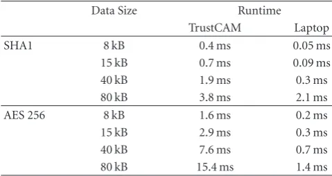
application is designed to ensure authenticity, integrity, freshness, and confidentiality for streamed images and videos. The implementation of the encryption block shown in Figure 7, follows the concepts presented in Section 5.4. For evaluation purposes we use sensitive regions of fixed size (100×100 pixels) that are extracted from the images. Such a JPEG compressed sensitive region typically consumes around 2.5 kB. As shown inTable 5, AES 256 encryption of this data takes less than 1 ms. Depending on resolution and color depth, the remaining, JPEG compressed background typically consumes between 12 kB (320×240, grayscale) and
40 kB (640×480, RGB). Encryption of the background image
together with the already encrypted sensitive region that is embedded as custom EXIF data takes between 3 ms and 8 ms.
Table 5provides additional performance figures for AES256 on TrustCAM. Binding of the AES session keys using the public binding keys of TPMStakes about 5 ms and has to be
done only at startup or when new session keys are created. These figures show that the overhead introduced by data encryption is relatively small and should be acceptable for most applications.Table 6shows the overall performance of the camera system in terms of achieved frames per second.
Specifically, the encryption columns shows the achieved
framerates when streaming encrypted images. Comparing
Table5: Average runtimes (100 runs) for SHA1 and AES 256 on the TrustCAM prototype. For comparison, measurements on a laptop (Core2 Duo, 1.6 GHz) are given.
Data Size Runtime
TrustCAM Laptop
SHA1 8 kB 0.4 ms 0.05 ms
15 kB 0.7 ms 0.09 ms
40 kB 1.9 ms 0.3 ms
80 kB 3.8 ms 2.1 ms
AES 256 8 kB 1.6 ms 0.2 ms
15 kB 2.9 ms 0.3 ms
40 kB 7.6 ms 0.7 ms
80 kB 15.4 ms 1.4 ms
these figures with the plain streaming case where images
are compressed and directly streamed, the impact on the framerate is between 0.3 and 1.5 frames.
This picture changes however, when considering image signing and timestamping as described inSection 5.3.Table 3
shows the runtime for the TPM TickStampBlob operation on the Atmel I2C TPM is about 800 ms without overheads. This runtime clearly makes it impossible to sign and timestamp every single image delivered by the camera since the effective framerate would be reduced to little more than one frame per second.
We consequently adapt the image timestamping and signing procedure such that sequences of images instead of individual images are timestamped. We accumulate the hashes for a group ofFframes in a way similar to the TPM’s PCR Extend operation:
AccSumFrm1...F =SHA1
AccSumFrm1...(F−1)
SHA1(Frmcurrent)
.
Table6: Framerates (avg. over 1000 frames) for different types of video streaming from TrustCAM to the control station via WiFi. The sensor delivers YUYV images at either 320×240 or 640×480 pixels. Optionally, they are converted to grayscale. Plain streaming shows the performance when images are JPEG compressed and streamed. For timestamping, image groups are timestamped by the TPM. The encryption column shows the achieved framerates if sensitive regions (100× 100 pixels) and the remaining background are encrypted before streaming. The last column presents the frames rates when doing both, encryption and timestamping.
Resolution Color Format Plain Streaming Timestamping Encryption Encryption + Timestamping
320×240 Gray 24.6 fps 24.4 fps 24.3 fps 24.1 fps
RGB24 23.8 fps 23.6 fps 22.3 fps 21.5 fps
640×480 Gray 12.8 fps 12.5 fps 11.8 fps 11.0 fps
RGB24 6.5 fps 6.3 fps 5.9 fps 5.7 fps
The accumulated hash forFframes is signed by TPMC:
TickStampRes=TPM TickStampBlobKSIG(TSN
TVCTRATEAccSumFrm1...F
. (15)
As shown inTable 5, SHA1 hashing of typical image sizes takes less than 2 ms. However, TPM timestamping of the hash takes a significant amount of time. We therefore do not wait for the TPM operation to complete but continue with the processing and streaming of video data. Specifically, the accumulation of the hash sum for the next group of images (beginning at frameF+ 1) is started. This continuous operation is possible since TPM commands are executed in parallel to the main processor. Once the TPM completes the timestamping command, the processing block is notified by the TPM Manager and the timestamp is retrieved. Together with the start and end indices of the group which are also included in the signature, the timestamp is attached to the next streamed frame. At this point, the accumulated hash sum of the next image group is sent to the TPM Manager for timestamping. The size of the image groups is automatically adapted to the current load of the system.
The presented approach allows us to overcome the problem of low TPM performance. By timestamping groups of frames instead of individual images, we can deliver a video stream without interruptions from TPM operations. At the same time, the security of the system is not reduced. For videos that are stored and viewed at a later point in time, integrity of images can easily be verified. For live video, integrity guarantees for the currently displayed frame cannot be given since the signature for the current image group is delivered at a later point in time. If there are no pending lifebeat requests, this delay typically is less than 1 s. Providing integrity and authenticity information for a live video stream with a delay of 1 s should be sufficient for most surveillance applications.
Note that our approach of signing groups of images also solves a problem that is introduced when using advanced video codecs such as MPEG2 or H.264. Contrary to the currently used Motion-JPEG, these codecs do not deliver full images for every video frame but differential information relative to one or more base frames. To provide meaningful signatures for such video data, it is necessary to sign groups of pictures including the base frames and the differential information instead of single frames. This means that our
approach is directly applicable for such advanced video codecs.
Another issue is that not every frame is associated with a TPM tick counter value at the time it is captured. The tick counter value of the group signature effectively corresponds to the capture time of the last frame of the group. This can be compensated, if the framerate at which the camera captures images is known. It is then possible to assign a world time interval not only to the last frame of a group but again to every frame. The order of frames within a group is guaranteed via the accumulated, signed hash sum. Correct group ordering is achieved via the group timestamps.
Aside from the already mentioned properties, the pro-posed approach of signing image groups also has an obvious disadvantage. If a frame of a group is lost, damaged, or manipulated, the integrity and authenticity of the entire group cannot be verified and the recording time cannot be determined.
As can be seen fromTable 6, the performance impact of timestamping on the achieved framerates is very small. We also evaluated the framerates when performing both, image encryption and timestamping. The reduction of framerates compared to simple streaming is between 0.5 and 2.3 fps. For larger image sizes a considerable performance reduction can be seen. This does not result from low encryption performance but from JPEG compression. JPEG encoding of
a 640×480 color image takes about 130 ms on TrustCAM.
Further performance details are provided in [9].
For the verification of the image signature, the control station computes the hash sum SHA1(Frmcurrent) for every
incoming frame and stores it in a local cache. Additionally, incoming frames are checked for an attached image group signature TickStampRes. As the attached data also contains the start and end indices of the image group, the control station now computes the expected accumulated hash sum ExpAccSumFrm1...F for theFframes indicated by the start and
end indices. It then loads the public signing key KSIG that
belongs to the expected camera from its local database and verifies the signature of the image group:
VerifyK
SIGpub
Tick StampRes, ExpAccSumFrm1...F
. (16)