Available Online atwww.ijcsmc.com
International Journal of Computer Science and Mobile Computing
A Monthly Journal of Computer Science and Information Technology
ISSN 2320–088X
IMPACT FACTOR: 6.017
IJCSMC, Vol. 6, Issue. 9, September 2017, pg.33 – 37
Implementation of Fast CORDIC
Algorithm for Embedded Application
1
Bandenamaj H Desai,
2Mahesh.B.Neelagar
¹Department of VLSI and Embedded Systems, (PG student) Centre for PG Studies, VTU Belagavi, India ²Assistant Professor Department of VLSI and Embedded Systems, Centre for PG Studies, VTU Belagavi, India
[email protected], 2 [email protected]
Abstract— More than half century invention of CORDIC algorithm the application of CORDIC algorithm is increases day by day in all areas of modern Engineering & Technology. A high speed and low energy consumed CORDIC for the calculation of elementary function is mainly required in real time embedded systems i.e. Multimedia , Robotics ,military applications Navigation of missiles, aero planes, satellites, DSP processors, image processing and arithmetic units in microprocessors. In nowadays in real time applications or DSP applications the power, speed and area are the important parameters on VLSI implementation level, the area also important as more area means more system cost. In original CORDIC requires more numbers of iterations therefore speed is less and area and power consumption also more. To overcome this Hybrid CORDIC is Implemented which has less number of iterations so speed is more and less requirement of resources. The code was synthesized using FPGA development tools for the Xilinx Spartan-3E xc3s500e family.
Index Terms- CORDIC, Hybrid CORDIC, ATR, FPGA DSP.
I. INTRODUCTION
CORDIC algorithm is developed to for navigation purpose of B-58 Bomber. Later the application of CORDIC is extended to many Fields in engineering, Such as military application, satellite navigation calculator Multimedia application DSP, Robotics, Digital communication. So every Day there are more application are emerging in CORDIC algorithm. Because of algorithm is a simple and efficient algorithm to calculate mathematical functions. Most of the engineering tasked with implementing a mathematical function such as sine, cosine or square root. The real beauty of this algorithm is that it can implement with a very small FPGA footprint. CORDIC requires only a small lookup table, along with logic to perform shift and additions. Importantly, the algorithm requires no dedicated multiplier or dividers. After invention of half centuries there are modified different type of CORDIC algorithms ar e developed according to application requirement. Speed, Area and Efficiency are main constrains in development of CORDIC for real time embedded applications.
II. CORDICALGORITHMPRINCIPLE
The CORDIC algorithm is a iterative method for performing vector rotations arbitrary angles with help of shifts and adds. There are two types of operation one is the rotational mode (RM) here the vector (xi; yi) is rotated by an angle Ө to obtain a new vector (xN;
yN), and in the vectoring mode (VM) here the algorithm computes the modulus R and phase α from the x-axis of the vector (x0; y0).
indexed by i = 0: N-1, was originally described for a circular coordinate system , then the algorithm was extended to linear and hyperbolic systems and described briefly in the following set of equations.
X
i+1=X
i-md
iY
i2
-i( 1)
Y
i+1=Y
i-d
iX
i2
-i(2)
Z
i+1=Z
i-d
iα
i(3)
α
i=2
-I,for Linear
tan
-1(2
-i), for Circular (4)
di=-sign(yi), , for VM
Sign(zi), for RM (5)
By taking proper values for the parameters m and αi, we can choose select the different coordinate systems. When m= 0, 1 or -1, and
the values of αi are , or the algorithm operates in linear, circular, and hyperbolic coordinate systems,
respectively.
Consider the rotation of a vector from the x-axis through an angle of, e.g., 25 degrees. Assuming that the rotation is to be accomplished in nine iterations (i.e. ,N=0...8), the set Q of predetermined angle constants that are used is as follows :
Q= {450, 26.5650 , 14.0360 ,7.1250 ,3.5760 ,1.790, 0.8950, 0.4480,0.22380}
In the CORDIC method, the rotation through 25 degrees is carried out by the following sequence of angular steps or pseudo rotations, that add up to approximately 25 degrees, as shown on Figure . 1:
250= {+450 - 26.5650 + 14.0360 - 7.1250 - 3.5760 +1.790 + 0.8950 + 0.4480 + 0.22380} = 25.12680.
III. THEHYBRIDCORDICALGORITHMS
In CORDIC algorithm an arbitrary angle is represented by using a set of constant angles instead of a normal radix , Which set is acting like a radix. Therefore, we may choose another set to represent the same angle just like what we do in representing numbers with different radices. The initial angle Ө is represented by a set of arctangent constants, called Arc Tangent Radix (ATR) .
For the circular coordinates, the radix set is:
{α1,α2,...…αN-1}={arctan20,arctan2-1,..,arctan2-N-1} (6)
which satisfies the CORDIC convergence theorem .
∑ (7)
To get actual value of , sequential operations are performed. All the previous iteration have To calculate before determine the Correct value of σifor any i, So there are mainly two constraints in paralization.
This application of compute rotation cannot be parallized fully because of each rotation must be applied to the vector get by the last rotation . However partial paralization can be done by combining two CORDIC into same cycle by sacrificing accuracy. Error is high when we merge higher number of conventional CORDIC iteration and it is not possible to get fully parallel and without error generation of rotation direction.
IV. THE HYBRID RADIX SETS
The circular ATR reaches the radix-2 coefficients has there are more number of iteration.
(8)
After the first few iterations, the error is less than thecube of the radix-2 ATR values. If the iteration index i islarge enough, the error in assuming that radix-2 coefficients are the same as circular ATRs is negligible in the finite precision N-bit representation. Therefore, if radix-2 is adopted as the radix set for the least significant part of the rotation directions, instead of the circular ATRs, the least significant part of the rotation directions will have about the same precision as the corresponding conventional ATRs. Based on this remark in partitioned Hybrid CORDIC most significant part must be A completely separated from least significant part.
∑
(9)
∑
(10)
∑
(11)
(Where )
( 12)
V. ARCHITECTURESFORTHEHYBRIDCORDICALGORITHMS
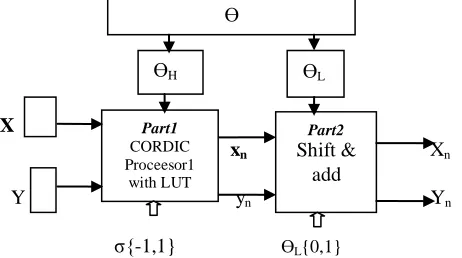
Partitioned Hybrid CORDIC also consist of Two parts as shown in figure 2 . Here given angle Ө is divided into two parts ӨH and
, ӨH rotation on X & Y operates on first processor and xn, yn values are obtained .This values are applied to second part which
does not have LUT . The second part consist on add shift from which final values of Xn, Yn is obtained. The first n CORDIC
iterations are performed on Most significant part of ATR by first processor . θH and θL are said to be coarse and fine sub angles respectively. In this architecture, θH is realized as arctangent of power of 2. Fig. 2 represents block diagram of Partitioned hybrid architecture . In this architecture, the LUTs, for storing the values of tan-1θ, are to be maintained for CORDIC processor 1. CORDIC processor 1 operates on most significant bits of θ to calculate the values of x- and y- coordinates using equations described in the section I. CORDIC part 2 does not require any LUTs and the calculation depends on the bits of θL. This serves as an added advantage as no LUTs are required during computation in CORDIC part 2. CORDIC part 2 operates on least significant bits of θ to give final values of the coordinates.
X
xn Xn
Y yn Yn
σ{-1,1} ӨL{0,1}
Fig. 2 The architecture for partitioned Hybrid CORDIC algorithm
Part1 CORDIC Proceesor1
with LUT
Part2
Shift & add
ӨH ӨL
(13)
In original CORDIC architecture there is no decomposition of θ, hence large space is required to store LUTs and number of iterations are also more due to this speed is less therefore it is very difficult to use in real time embedded applications . In hybrid architecture, part of computation is performed using same architecture as used for original CORDIC . Partitioned Hybrid CORDIC or simply Hybrid CORDIC requires one CORDIC processor and second simple shift & add unit. CORDIC processor 1 calculates intermediate values of x- and y- coordinate using the same method as original CORDIC architecture. It requires LUTs to save values of tan-1θ. Output of processor 1 is then passed to part 2 shifts and add unit which computes x- and y-coordinates without using LUTs thus, making it less complicated than processor 1. Here, the decision is made on the basis of the bits of θLrather than σj as shown in equation 14.
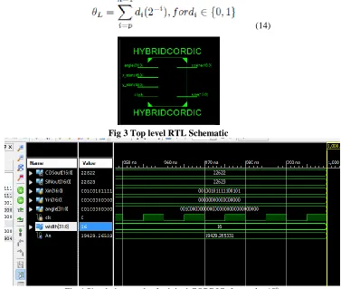
(14)
Fig 3 Top level RTL Schematic
Fig:4 Simulation result of original CORDIC for angle 45o
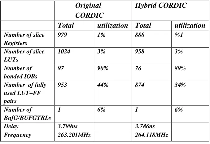
Table 1: Comparison between Hybrid and Original CORIC.
From simulation result it is found that to get the value of sine cosine 450 Binary 32 bit 00100000000000000000000000000000 is provide as input angle and which is scaled value of 45o. So in result obtained is 22623, 22622 for sine and cosine respectively. After dividing this value by 32000 which is scale factor we get 0.70696875 & 0.7069375 values respectively. Therefore sin(45o)=.707106781 cos (45o)= 0.707106781 which is accurate result with less error obtained from simulation of Hybrid CORDIC. From table the comparison is it is found that Delay and resource required for Hybrid CORDIC is less compare to original CORDIC algorithm . The iteration is also required is reduce by half .So this Hybrid Cordic algorithm can be used in embedded system real time applications.
VI. CONCLUSION
Hybrid CORDIC processor in rotation mode is carried out in this paper. The given angle Ө is decomposed into fine and coarse sub angles. The latency of the architecture reduced to as compare to original CORDIC. As shown in the comparative study (table1) the resource utilization is also less than Original CORDIC architectures. As this Hybrid CORDIC requires less iteration and resources so this can be used as coprocessor in DSP and embedded applications.
References
[1] J. E. Volder, “The CORDIC trigonometric computing technique,”IRETrans. Electron. Computers, vol. EC-8, pp. 330334, Sept. 1959. [2] P. K. Meher et al., “50 years of CORDIC: Algorithms, Architectures and Applications,” IEEE Trans. Circuits Syst. I, vol. 56, no. 9, pp 18931907,Sep. 2009.
[3] Satish Sharma et al, “Implementation of Para-CORDIC algorithm and it sapplication in Satellite Communication,” IEEE Int. Conf. on Advances in Recent Technologies in Communication and Computing (ARTCom), Oct.2009, pp. 266-270.
[4] S. Wang, V. Piuri, and J. E. Swartzlander, “Hybrid CORDIC algorithms,”IEEE Trans. Comput., vol. 46, no. 11, pp. 12021207, Nov.1997. [5] Supriya Aggarwal and Pramod K. Meher,“Reconfigurable CORDICArchitectures for Multi-mode and Multi-trajectory Operations,” IEEE Int.Symp. on Circuits and Systems (ISCAS), June 2014, pp. 2490-2494.
[6] Abubeker K.M, Sabana Backer, and Abey Mathew Varghese, “Serial and Parallel Implementation of CORDIC Architecture: A Comparative Approach,” IEEE Int. Conf. on Microelectronics, Communication and Renewable Energy (ICMiCR), June 2013, pp. 1-6. [7] E. Antelo, J. Villalba, J. D. Bruguera, and E. L. Zapatai, “High performancerotation architectures based on the radix-4 CORDIC algorithm,” IEEE Trans. Compute., vol. 46, no. 8, pp. 855870, Aug. 1997.
[8] E. Antelo, T. Lang, and J. D. Bruguera, “Very-high radix circular CORDIC: Vectoring and unified rotation/vectoring,” IEEE Trans.
Compute., vol. 49, no. 7, pp. 727739, July 2000.
[9] H. Hu and S. Naganathan, “An angle recoding method for CORDIC algorithm implementation,” IEEE Trans. Compute., vol. 42, no. 1, pp. 99102, Jan. 1993.
Original
CORDIC
Hybrid CORDIC
Total
utilization Total
utilization
Number of slice Registers
979 1% 888 %1
Number of slice LUTs
1024 3% 958 3%
Number of bonded IOBs
97 90% 76 89%
Number of fully used LUT+FF pairs
953 44% 874 34%
Number of BufG/BUFGTRLs
1 6% 1 6%
Delay 3.799ns 3.786ns