Available online:
https://edupediapublications.org/journals/index.php/IJR/
P a g e
| 1546
Multi Focus Image Fusion Based On Spatial Frequency and
Analysis under SWT Domain
B Yugandhar Reddy & Dr.N.Ramamurthy
M.Tech, ECE G Pullaiah College of Engineering and Technology Kurnool, A.P, India
[email protected]
Assoc.Professor, ECE G Pullaiah College of Engineering and Technology Kurnool, A.P, India
[email protected]
ABSTRACT
The project presents multi focus image fusion using stationary wavelet transform with local directional pattern and spatial frequency analysis. Multi focus image fusion in wireless visual sensor networks is a process of fusing two or more images to obtain a new one which contains a more accurate description of the scene than any of the individual source images. In this project, the proposed model utilizes the multi scale decomposition done by stationary wavelet transform for fusing the images in its frequency domain. It decomposes an image into two different components like structural and textural information. It doesn’t down sample the image while transforming into frequency domain. So it preserves the edge texture details while reconstructing image from its frequency domain. It is used to reduce the problems like blocking, ringing artifacts occurs because of DCT and DWT. The low frequency sub band coefficients are fused by selecting coefficient having maximum spatial frequency. It indicates the overall active level of an image. The high frequency sub band coefficients are fused by selecting coefficients having maximum code value. Finally, fused two different frequency sub bands are inverse transformed to reconstruct fused image. The system performance will be evaluated by using the parameters such as Peak signal to noise ratio, correlation and entropy.
General Terms
Image Fusion, frequency domain, DCT, DWT.
Keywords
DCT, image fusion, multi-focus, spatial frequency.
1.
INTRODUCTION
The developments in the field of sensing technologies multi-sensor systems have become a reality in a various fields such as remote sensing, medical imaging, machine vision and the military applications for which they were developed. The result of the use of these techniques is a increaseof the amount of data available. Image fusion provides an effective way of reducing the increasing volume of information while at the same time extracting all the useful information from the source images. Multi-sensor data often presents complementary information, so image fusion provides an effective method to enable comparison and analysis of data. The aim of image fusion, apart from reducing the amount of data, is to create new images that are more suitable for the purposes of human/machine perception, and
for further image processing tasks such as segmentation, object detection or target recognition in applications such as remote sensing and medical imaging. For example, visible-band and infrared images may be fused to aid pilots landing aircraft in poor visibility.
Multi-sensor images often have different geometric representations, which have to be transformed to a common representation for fusion. This representation should retain the best resolution of sensor. A prerequisite for successful in image fusion is the alignment of multi-sensor images. However, image fusion does not necessarily provide multisensory sources, there are interesting applications for both single-sensor and multi-sensor image fusion.
2.
PROPOSED WORK
Figure 1: proposed Schematic diagram for fusing images coded in JPEG format..
Available online:
https://edupediapublications.org/journals/index.php/IJR/
P a g e
| 1547
1) Decode and de-quantize the source images, and then divide them into blocks of size 8*8. Denote the block pair at location (i, j) by Ai,j and Bi,j respectively.
2) Compute the spatial frequency of each block by (12), and denote the results of Ai,j and Bi,j by SFAi,j and SFBi,j, respectively.
3) Compare the spatial frequencies of two corresponding blocks to decide which should be used to construct the fused image. Create a decision map W to record the feature comparison results according to a selection rule:
Here, T is a user-defined threshold.
4)Apply a consistency verification process to improve quality of the output image. Use a 3*3 majority filter to obtain a refined decision map R:
Then, obtain the DCT representation of the fused image F based on R as:
5) Quantize the resulting DCT coefficients with a standard quantization table in the standard JPEG coder and then use entropy coding to produce the output bit stream.
3. IMAGE FUSION
In wireless visual sensor networks, multiple sensors are applied to obtain images of the same scene, and acentralized fusion center combines source images from multiple sensors into a single image, which is more suitable for human visual and machine perception So far, a lot of researches have concentrated on image fusion performed in the spatial domain. Methods based on multi-scale transform such as discrete wavelet transform (DWT), shift invariant discrete wavelet transform (SIDWT), and non-subsampled contour let transform (NSCT) are popular. However, most of the image fusion approaches based on multi-scale transform are complex and time-consuming, which limits their applications for wireless visual sensor networks equipped with constrained resources. In WVSN, images are compressed before transmission to the other nodes. When the source images are saved or transmitted in DCT based standards, the methods applied in DCT domain will reduce computation complexity considerably. Recently, several image fusion techniques in DCT domain have been proposed. Tang et al. proposed two methods in DCT domain, namely.
3.1.Standard Image Fusion Methods
Image fusion methods can be broadly classified into two groups - spatial domain fusion and transform domain fusion.
The fusion methods such as averaging, Brovey method, principal component analysis (PCA) and IHS based methods fall under spatial domain approaches. Another important spatial domain fusion method is the high pass filtering based technique. Here the high frequency details are injected into upsampled version of MS images. The disadvantage of spatial domain approaches is that they produce spatial distortion in the fused image. Spectral distortion becomes a negative factor while we go for further processing, such as classification problem. Spatial distortion can be very well handled by frequency domain approaches on image fusion. The multiresolution analysis has become a very useful tool for analysing remote sensing images. The discrete wavelet transform has become a very useful tool for fusion. Some other fusion methods are also there, such as Laplacian pyramid based, curvelet transform based etc. These methods show a better performance in spatial and spectral quality of the fused image compared to other spatial methods of fusion.
The images used in image fusion should already be registered. Misregistration is a major source of error in image fusion. Some well-known image fusion methods are:
Available online:
https://edupediapublications.org/journals/index.php/IJR/
P a g e
| 1548
show a better performance in spatial and spectral quality of the fused image compared to other spatial methods of fusion.
The images used in image fusion should already be registered. Misregistration is a major source of error in image fusion. Some well-known image fusion methods are:
• High pass filtering technique
• IHS transform based image fusion
• PCA based image fusion
• Wavelet transform image fusion
• Pair-wise spatial frequency matching.
1. Remote Sensing Image Fusion
Image fusion in remote sensing has several application domains. An important domain is the multi-resolution image fusion (commonly referred to pan-sharpening). In satellite imagery we can have two types of images
• Panchromatic images - An image collected in the broad visual wavelength range but rendered in black and white.
• Multispectral images - Images optically acquired in more than one spectral or wavelength interval. Each individual image is usually of the same physical area and scale but of a different spectral band.
The SPOT PAN satellite provides high resolution (10m pixel) panchromatic data. While the LANDSAT TM satellite provides low resolution (30m pixel) multispectral images. Image fusion attempts to merge these images and produce a single high resolution multispectral image.
The standard merging methods of image fusion are based on Red-Green-Blue (RGB) to Intensity-Hue-Saturation (IHS) transformation. The usual steps involved in satellite image fusion are as follows:
1. Resize the low resolution multispectral images to the same size as the panchromatic image.
2. Transform the R, G and B bands of the multispectral image into IHS components.
3. Modify the panchromatic image with respect to the multispectral image. This is usually performed by histogram matching of the panchromatic image with Intensity component of the multispectral images as reference.
4. Replace the intensity component by the panchromatic image and perform inverse transformation to obtain a high resolution multispectral image.
An explanation of how to do Pan-sharpening in Photoshop. For other applications of image in remote sensing, interested readers can refer to: Beyond Pan-sharpening: Pixel-level Fusion in Remote Sensing Applications.
2. Medical Image Fusion
Image fusion has become a common term used within medical diagnostics and treatment. The term is used when multiple images of a patient are registered and overlaid or merged to provide additional information. Fused images may be created from multiple images from the same imaging modality. In radiology and radiation oncology, these images serve different purposes. For example, CT images are used more often to ascertain differences in tissue density while MRI images are typically used to diagnose brain tumors.
For accurate diagnoses, radiologists must integrate information from multiple image formats. Fused, anatomically consistent images are especially beneficial in diagnosing and treating cancer. With the advent of these new technologies, radiation oncologists can take full advantage of intensity modulated radiation therapy (IMRT). Being able to overlay diagnostic images into radiation planning images results in more accurate IMRT target tumor volumes.
3.2.MULTIFOCUSOF FUSION IMAGE
METHODS
Available online:
https://edupediapublications.org/journals/index.php/IJR/
P a g e
| 1549
relevant information from the input images - The image fusion should not introduce artifacts which can lead to a wrong diagnosis One of the important pre-processing steps for the fusion process is image registration. Image registration is the process of transforming different sets of data into one coordinate system. Image fusion find application in the area of navigation guidance, object detection and recognition, medical diagnosis, satellite imaging for remote sensing, military and civilian surveillance, etc. Image fusion algorithms can be categorized into different levels: pixel, feature, and decision levels. Pixel level fusion works directly on the pixels of source images while feature level fusion algorithms operate on features extracted from the source images.
4.
EXPERIMENT RESULTS
In this work we have taken five different images namely Medical and satellite images to test quality of retrieved image. Experimental results show comparison between DCT and DWT in terms of PSNR, MSE, Entropy, Correlation, and SSIM.
4.1. For Medical image:
Parameters
DCT
DWT
MSE
10.9727
6.5083
PSNR
37.7277
39.9967
ENTROPY
4.5076
4.7370
CORRELATION 0.0037
0.7022
SSIM
0.0030
0.6923
Table 1: results for cameraman image
Graph 1: graph for cameraman image
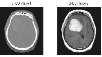
Figure 1a: input medical image for DCT fusion
Figure 1b: PCA medical image for DCT Fusion.
Figure 1c: output fused medical image for DCT Fusion.
Figure 2a: input medical image for DWT Fusion.
Available online:
https://edupediapublications.org/journals/index.php/IJR/
P a g e
| 1550
Figure 2c: Reconstructed medical image for DWT Fusion.
Figure 2d: output DWT Fusion medical image
4.1. For Satellite image:
Parameters
DCT
DWT
MSE
11.3020
09.4467
PSNR
37.5993
38.3780
ENTROPY
7.2709
07.2564
CORRELATION
-0.0008
0.4284
SSIM
0.0027
0.4853
Table 2: results for satellite image
Graph 1: Quality assessment for satellite image
Figure 3a: input satellite image for DCT Fusion.
Figure 3b: PCA satellite image for DCT Fusion.
Available online:
https://edupediapublications.org/journals/index.php/IJR/
P a g e
| 1551
Figure 4a: input satellite image for DWT Fusion.
Figure 4b: DWT satellite image Fusion
Figure 4c: Reconstructed satellite image for DWT Fusion.
Figure 4d: output DWT Fusion satellite image.
5.
CONCLUSION
A new approach based on spatial frequency for fusion of multi-focus images has been proposed in the DCT domain instead of the spatial domain. We evaluate the performance of the proposed method with various evaluation metrics and it is found that the performance of fusion in the DCT domain is superior to that of conventional approaches based on DCT and the state-of-the-art methods including DWT, SIDWT, and NSCT, in terms of visual quality and quantitative parameters. Moreover, the proposed method is simple to implement and computationally efficient when the source images are coded in JPEG format, especially in wireless visual sensor networks.
6.
ACKNOWLEDGMENTS
Author wants to special thank Dr.N.RAMAMURTHY Assoc.Professor, ECE department G Pullaiah College of Engineering, and Technology Kurnool, A.P, India. For his constructive suggestions and for comments that greatly improved the manuscript. Although any errors are my own and should not tarnish the reputations of these esteemed person.
7.
REFERENCES
1.