Improvement of Power Quality Features Using Dual Voltage
Source Inverter
G.Isaac ; M.Mahesh ; P V Samrat
M.Tech(Power Electronics and Industrial Drives), JNTU College Of Engg, Hyd M.Tech (Electrical Power Systems), Ellenki College of Engineering
M.E., College of Engineering,Osmania University
ABSTRACT: This paper provides a dual voltage deliver inverter (DVSI) software to improve the
strength nice further to reliability of the
microgridsystem. The proposed scheme is absolutely composed of 2 inverters, which makes it feasible for the microgrid to change powerproduced by way of the disbursed power resources (ders) and to compensate the nearby unbalanced as well as nonlinear load.The control algorithms are genuinely developed predicated on on the spot symmetrical factor theory (ISCT) to use DVSI in grid posting and grid injecting methods. The proposed plan has more dependability, decrease bandwidthdependence at the critical inverter, less pricey because of to lessen in filtration size, and much higher use of micro grid capacity while operating with decreased dc link voltage score for the vital inverter. The DVSI is really made through the characteristics layout a promising alternative for micro grid offering hypersensitive plenty. The manage and topology algorithm are simply verified through experimental outcomes and complete simulation.
KEYWORDS: DVSI, Instantaneous Symmetrical Aspect Theory(ISCT), DERs.
I. INTRODUCTION
To drive the energy device there are many models or pattern with more renewable strength sources interlinkedwith the network with the aid of the usage of allotted technology (DG). These DG gadgets can manage of nearby era, storagefacilities from a micro-grid. A micro-grid, energy may be taken from the different renewable power sourcessuch as fuel cells, photovoltaic structures, and wind electricity structures are merged to grid and hundreds using (%)strength digital converters. To alternate the electricity from micro-grid to grid and linked load by
using the usage of aninteractive grid inverter. This micro-grid inverter can both work in a grid sharing mode or in grid injecting mode, the grid sharing is finished at the same time as offering part of nearby load, the grid injecting is accomplished by way of injecting powerto the primary grid.some other critical issue is retaining power excellent it has to be completed while the microgrid is connectedto the principle grid. The range of feeder impedance inside the distribution systems, the propagation of these harmoniccurrents distorts the voltage on the point of not unusual coupling (%).The microgrid producing power from most important voltage supply inverter (MVSI) as actual power and the compensationof reactive, harmonic, and unbalanced load compensation which carried out with the aid of (AVSI) auxiliary voltage sourceinverter. An important advantage of MVSI that it can continually be used to inject real power to the grid with ratedcapacity and it additionally as enough renewable power is available at the dc hyperlink.the 2 inverters is supplies general power to the load and also reduces the switching losses throughout thesemiconductor switches. By this reduction of losses will boom the gadget reliability whilst it compares tosingle inverter. On this scheme a smaller length modular inverters are used. Because these inverters can function athigh switching frequencies with a reduced size of interfacing inductor, in order that the clear out fee gets reduced.
unmarried dc storage capacitor with 3-section three-leg inverter structurecan be used. It reduces the dc-link voltage requirement of the main inverter. As a result, the usage of AVSI and dvsiinverters within the device structure which gives the machine reliability, micro-grid strength is applied better andalso reduces the voltage rating of the grid.
Control algorithms is evolved (ISCT) to operate DVSI in grid connected mode whilst considering nonstiff grid voltage. The dq0 transformation approach is used to extract the essential fine series of pccvoltage q0 transformation. The manipulate approach are measured with the parallel inverters connected to a threephase 4-cord distribution device.
II. PROPOSED SYSTEM
Electric power quality (EPQ), or simply Power quality,refers to "maintaining the near sinusoidal waveform of powerdistribution bus voltages and currents at rated magnitude andfrequency.",[1] determining the fitness of electric power toconsumer devices. Synchronization of the voltage frequencyand phase allows electrical systems to function in theirintended manner without significant loss of performance orlife. The term is used to describe electric power that drives anelectrical load and the load's ability to function properly.Without the proper power, an electrical device (or load) maymalfunction, fail prematurely or not operate at all. There aremany ways in which electric power can be of poor quality andmany more causes of such poor quality power. The electricpower industry comprises electricity generation (AC power),electric power transmission and ultimately electric powerdistribution to an electricity meter located at the premises ofthe end user of the electric power.
The electricity then movesthrough the wiring system of the end user until it reaches theload. The complexity of the system to move electric energyfrom the point of production to the point of consumptioncombined with variations in weather, generation, demand andother factors provide many opportunities for the quality ofsupply to be compromised. While "power quality" is aconvenient
term for many, it is the quality of the voltagerather than power or electric current that is actually describedby the term. Power is simply the flow of energy and thecurrent demanded by a load is largely uncontrollable.
The proposed DVSI topology is shown in Fig. 1. It consistsof a neutral point clamped (NPC) inverter to realize AVSI anda three-leg inverter for MVSI. These are connected to grid atthe PCC and supplying a nonlinear and unbalanced load. Thefunction of the AVSI is to compensate the reactive,harmonics, and unbalance components in load currents. Here,load currents in three phases are represented by ila, ilb, andilc, respectively. Also, ig(abc), iμgm(abc), and iμgx(abc)show grid currents, MVSI currents, and AVSI currents inthree phases, respectively. The dc link of the AVSI utilizes asplit capacitor topology, with two capacitors C1 and C2. TheMVSI delivers the available power at distributed energyresource (DER) to grid. The DER can be a dc source or an acsource with rectifier coupled to dc link. Usually, renewableenergy sources like fuel cell and PV generate power atvariable low dc voltage, while the variable speed windturbines generate power at variable ac voltage. Therefore, thepower generated from these sources use a power conditioningstage before it is connected to the input of MVSI.
Fig. 1. Topology of proposed DVSI scheme
assumed to have some amount offeeder resistance Rg
and inductance Lg. Due to the presenceof this feeder
impedance, PCC voltage is affected withharmonics.
A. Design of DVSI Parameters
AVSI: The vital parameters of AVSI like dc link voltage(Vdc), dc storage capacitors (C2 and C1), interfacinginductance (Lfx), as well as hysteresis band (±hx) are actually selected basedon the layout technique of split capacitor DSTATCOM topology. The dc link voltage across each capacitor is actually taken as1.6 times the good of phase voltage. The total dc link voltagereference (Vdcref) is actually discovered to remain 1040 V. Values of dccapacitors of AVSI are picked based on the shift in dc link voltage during transients. Let total load rating is actually S kVA. In themost severe situation, the load power might differ from minimum to maximum, i.e., from zero to S kVA. AVSI requires to exchangepower that is real during transient to keep the ton power demand. This transfer of power that is real during the transient willoutcome in deviation of capacitor voltage from its reference worth. Believe that the voltage controller requires n cycles, i.e.,nT seconds to act, in which T is actually the process time period. Hence,highest power exchange by AVSI during transient is going to be nST. This energy is going to be identical to shift in the capacitorsaved energy. Therefore
1
2𝐶1(𝑉𝑑𝑐𝑟 2 − 𝑉
𝑑𝑐12 ) = 𝑛𝑆𝑇 ……….. (1)
whereVdcr and Vdc1 are the reference dc voltage andmaximum permissible dc voltage across C1 during transient,respectively. Here, S =5 kVA, Vdcr = 520 V, Vdc1 = 0.8Vdcr or 1.2 Vdcr, n = 1, and T = 0.02 s. Substituting thesevalues in (1), the dclink capacitance (C1) is calculated to be2000 μF. Same value of capacitance is selected for C2. Theinterfacing inductance is given by
𝐿𝑓𝑥 = 1.6𝑉𝑚
4ℎ𝑥𝑓𝑚𝑎𝑥……….. (2)
Assuming a maximum switching frequency (fmax) of 10kHz and hysteresis band (hx) as 5%of load current
(0.5 A),the value of Lfx is calculated to be 26 mH. 2) MVSI: TheMVSI uses a three-leg inverter topology. Its dc-link voltage isobtained as 1.15 Vml, where Vml is the peak value of linevoltage. This is calculated to be 648 V. Also,MVSI supplies abalanced sinusoidal current at unity power factor. So, zerosequence switching harmonics will be absent in the outputcurrent of MVSI. This reduces the filter requirement forMVSI as compared to AVSI. In this analysis, a filterinductance (Lfm) of 5 mH is used.
B. GRID-TIE Inverter:
A grid-tie inverter is a power inverter that converts direct current (DC) electricity into alternating current (AC) with an ability to synchronize to interface with a utility line. Its applications are converting DC sources such as solar panels or small wind turbines into AC for tying with the grid. Residences and businesses that have a grid-tied electrical system are permitted in many countries to sell their energy to the utility grid. Electricity delivered to the grid can be compensated in several ways. "Net metering" is where the entity that owns the renewable energy power source receives compensation from the utility for its net outflow of power.
degrades either the realpower injection or the load compensation capabilities. Thispaper demonstrates a dual voltage source inverter (DVSI)scheme, in which the power generated by the micro grid isinjected as real power by the main voltage source inverter(MVSI) and the reactive, harmonic, and unbalanced loadcompensation is performed by auxiliary voltage sourceinverter (AVSI).
This has an advantage that the rated capacity of MVSI canalways be used to inject real power to the grid, if sufficientrenewable power is available at the dc link. In the DVSIscheme, as total load power is supplied by two inverters,power losses across the semiconductor switches of eachinverter are reduced. This increases its reliability as comparedto a single inverter with multifunctional capabilities. Also,smaller size modular inverters can operate at high switchingfrequencies with a reduced size of interfacing inductor, thefilter cost gets reduced. Moreover, as the main inverter issupplying real power, the inverter has to track thefundamental positive sequence of current. This reduces thebandwidth requirement of the main inverter. The inverters inthe proposed scheme use two separate dc links. Since theauxiliary inverter is supplying zero sequence of load current,a three-phase three-leg inverter topology with a single dcstorage capacitor can be used for the main inverter. This inturn reduces the dc-link voltage requirement of the maininverter. Thus, the use of two separate inverters in the
proposed DVSI scheme provides increased reliability, betterutilization of micro grid power, reduced dc grid voltagerating, less bandwidth requirement of the main inverter, andreduced filter size. Control algorithms are developed byinstantaneous symmetrical component theory (ISCT) tooperate DVSI in grid-connected mode, while considering nonstiff grid voltage. The extraction of fundamental positivesequence of PCC voltage is done by dq0 transformation. Thecontrol strategy is tested with two parallel inverters connectedto a three-phase four-wire distribution system. Effectivenessof the proposed control algorithm is validated throughdetailed simulation and experimental results.
III. SIMULATION AND RESULTS
Fig. 2 Simulation diagram showing the control strategy ofproposed D VSI scheme
Fig.3Voltage swell during non linear load parallel to thedual inverter connected load
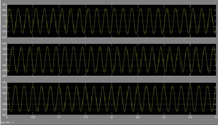
Fig.5Voltages and currents of 3-phase load
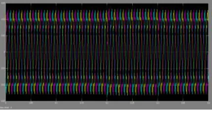
Fig .6 dual fed line of 3-phase currents
IV. CONCLUSION
A DVSI scheme is proposed for microgrid structures with superior energy nice. Control algorithms are advanced togenerate reference currents for DVSI the usage of ISCT. The proposed scheme has the functionality to change electricity fromdistributed turbines (dgs) and also to compensate the local unbalanced and nonlinear load. The performance of theproposed scheme has been established thru simulation and experimental studies. In comparison to a unmarried inverterwith multifunctional competencies, a DVSI has many blessings consisting of, improved reliability, decrease value due to thereduction in clear out size, and extra utilization of inverter potential to inject real power from dgs to microgrid. Furthermore,the usage of 3-phase, three twine topology for the main inverter reduces the dc-hyperlink voltage requirement.
REFERENCES
[1]. A.Kahrobaeian and Y.-R.Mohamed,―Interactive distributedgeneration interface for flexible micro-grid operation in smartdistribution systems, IEEE Trans. Sustain. Energy, vol. 3, no.2, pp. 295–305, Apr. 2012.
[2] N. R. Tummuru, M. K. Mishra, and S. Srinivas,―Multifunctional VSC controlled microgrid usinginstantaneous symmetrical components theory,IEEE Trans.Sustain. Energy, vol. 5, no. 1, pp. 313–322, Jan. 2014.
[3] Y. Zhang, N. Gatsis, and G. Giannakis, ―Robust energymanagement for microgrids with high-penetrationrenewables, IEEE Trans. Sustain. Energy, vol. 4, no. 4, pp.944–953, Oct. 2013.
[4] R. Majumder, A. Ghosh, G. Ledwich, and F. Zare, Loadsharing and power quality enhanced operation of a distributedmicrogrid, IET Renewable Power Gener., vol. 3, no. 2, pp.109–119, Jun. 2009. [5] J. Guerrero, P. C. Loh, T.-L. Lee, and M. Chandorkar,Advanced control architectures for intelligent microgrids Part II: Power quality, energy storage, and ac/dc microgrids,IEEE Trans. Ind. Electron., vol. 60, no. 4, pp. 1263–1270,Dec. 2013. [6] Y. Li, D. Vilathgamuwa, and P. C. Loh, Microgrid powerquality enhancement using a three-phase four-wire gridinterfacing compensator,IEEE Trans. Ind. Appl., vol. 41, no.6, pp. 1707–1719, Nov. 2005.
[7] M. Schonardie, R. Coelho, R. Schweitzer, and D. Martins,Control of the active and reactive power using dq0transformation in a three-phase grid-connected PV system, inProc. IEEE Int. Symp. Ind. Electron., May 2012, pp. 264–269.
[8] R. S. Bajpai and R. Gupta, ―Voltage and power flowcontrol of grid connected wind generation system usingDSTATCOM, in Proc. IEEE Power Energy Soc. Gen.Meeting—Convers. Del. Elect. Energy 21st Century, Jul.2008, pp. 1–6.
UPQC bassed onmultilevel topology, International science press I J C T A, 8(4), 2015, pp. 1433-1443. [10] P. Kalyana sundaram, R. Neela. “Automation classification of power quality disturbances using MLP network”, Internationalscience press I J C T A, 8(4), 2015, pp. 1337-1350.
Authors Details:
G.Isaac Having 9+ Years Of Exp As Asst Professor In The Dept Of Electrical And Electronics Engg, Presently Working As Asst Professor In Global Institute Of Engg And Technology, Jntu, Hyderabad. I Did B.Tech From Royal College Of Engg (Presently Hyderabad Inst Of Engg And Technology And Management In The Year 2005 And M.Tech (Power Electronics And Industrial Drives) From Jntu College Of Engg Hyd In Year 2010.
M.Mahesh completed M.tech (Electrical Power Systems) from Ellenki college of engineering in the year 2016. My areas of interest are power systems, machines.