Design and Implementation of a DSP-Based MIMO
System Prototype for Real-Time Demonstration
and Indoor Channel Measurements
Raqibul Mostafa, Ran Gozali, Ramesh Chembil Palat, Max Robert, William G. Newhall, Brian D. Woerner, and Jeffrey H. Reed
Mobile and Portable Radio Research Group, Virginia Polytechnic Institute and State University, 432 Durham Hall, Mail Stop 0350, Blacksburg, VA 24061, USA
Emails:[email protected],[email protected],[email protected],[email protected],[email protected], [email protected],[email protected]
Received 27 January 2004; Revised 28 February 2005
The design and implementation of the Virginia Tech Space-Time Advanced Radio (VT-STAR), a multiple antenna element space-time (ST) processing prototype testbed, is presented. The testbed is a research tool for comparing practical and theoretical perfor-mance metrics (e.g., throughput, link reliability) in different wireless channel conditions. The prototype builds around software-defined radio (SDR) concepts on a DSP platform and provides the flexibility to implement various forms of ST techniques. Diff er-ent componer-ents of the system are described in detail, including the software implemer-entation, I/O schemes with custom hardware, and data transfer mechanisms between the DSP and the host PC. Two different example realizations are presented, a real-time demonstration and an offline measurement tool. Finally, some representative measurement results obtained in indoor environ-ments are presented. These results show VT-STAR to be a promising tool for performing MIMO experienviron-ments and generating channel measurements that can complement simulation studies in this area.
Keywords and phrases:space-time codes, MIMO, DSP C67, prototype, wireless communications.
1. INTRODUCTION
With the integration of Internet and multimedia applica-tions in next-generation wireless communicaapplica-tions, the de-mand for reliable high-data-rate services is rapidly growing. The wireless channel introduces a variety of impairments to the transmitted signal, including large-scale and small-scale fading, channel-induced intersymbol interference (ISI), noise and multiuser interference. To mitigate these phenom-ena, diversity can be exploited to enhance performance over a broad range of channel realizations. Space-time coding (STC) schemes implement multiple forms of diversity by combining the channel code design and the use of multiple transmit and receive antennas, thereby creating a multiple-input multiple-output (MIMO) channel. The encoded data is split into nT streams that are simultaneously transmit-ted usingnT transmit antennas. The received signal is a lin-ear superposition of these simultaneous transmitted sym-bols corrupted by noise, interference, and channel-induced ISI. Space-time decoding algorithms using channel estima-tion techniques are incorporated at the receiver to achieve diversity and coding gains. Various techniques that exploit the capabilities of MIMO channels have been proposed in the literature. Among them, the main classes are
(i) BLAST—Bell Labs layered space-time architecture, proposed by Foschini et al. [1];
(ii) space-time trellis codes (STTC), proposed originally by Tarokh et al. [2];
(iii) space-time block codes (STBC), proposed originally by Alamouti [3].
While BLAST technology strives towards increasing the throughput of wireless systems by an order of magnitude, space-time codes allow for improved link reliability by ex-ploiting the spatial and temporal diversity of the MIMO channel. Space-time codes have been adopted recently by the 3G standardization committee for implementation as one of the transmit diversity modes in 3G wireless networks [4].
not realistic. In fact, the performance of the space-time ar-chitecture relies heavily on accurate channel tracking process [5]. In order to explore the multiple aspects of MIMO sys-tems described above, the goal of the Virginia Tech Space-Time Advanced Radio (VT-STAR) [6] is to create a platform that allows the evaluation of the channel and the implemen-tation of various space-time algorithms. Employing software defined radio (SDR) concepts, a variety of baseband con-figurations can be implemented in software only with min-imal nonprogrammable hardware; furthermore, these soft-ware modules may be leveraged by future research activities. There are several MIMO testbed systems that have been reported in the recent literature and we briefly summarize some of these. It is possible to measure some of the charac-teristics of the channel using multiple elements only at the receiver. To this end, a system with 1 antenna element at the transmitter and 8 antenna elements at the receiver, denoted 1×8 system, operating at 2.4 GHz was developed at Ohio State University to measure the wireless channel in receive diversity settings [7]. Another approach to measure the char-acteristics of the MIMO channel is to use a wide variety of single-input single-output (SISO) measurements with static channel conditions [8]. By performing this series of measure-ments, the authors claim to measure the behavior of a MIMO channel. In [9], a 4×4 MIMO system was created that per-forms pseudo-parallel transmissions, a switch cycles through antennas every 200 microseconds, and performs parallel re-ceptions of the signals, estimating the MIMO channel. Wal-lace and Jensen [10] implemented a 4×4 MIMO system with a wide variety of antenna geometries that was limited to data collection capability only. Yu et al. [11] reported the use of an 8×8 system for characterizing narrowband indoor propaga-tion channels at 5.2 GHz. The authors in [12] report the field test of a 4×4 system with 30 kHz bandwidth in outdoor mo-bile environments and the MIMO measurements were based on transmitting separate orthogonal Walsh sequences from each transmit antenna. In [13], the spectral efficiencies for a BLAST-based communication system were verified by out-door channel measurements using a 5×7 system developed at Bell Labs. The testbed used a 2.44 GHz narrowband system where five narrowband frequencies were transmitted simul-taneously from the five transmitting antennas. In [14], the authors reported a rapid prototyping system using FPGA for implementing a 4×4 BLAST system over the UMTS stan-dard with 5 MHz bandwidth. The authors in [15] report a 1×8 MIMO channel measurement system that was used to emulate multiple virtual-antenna operation and to study the capacity of both frequency-flat and frequency-selective chan-nels at 5.2 GHz. A 3×3 broadband 20 MHz V-BLAST-based MIMO-OFDM prototype was developed for 802.11a stan-dard in [16], where digital downconversion and signal con-ditioning were implemented on FPGA boards and the sig-nal processing was done offline on collected data. A simple Alamouti scheme using with QPSK modulation for 2×2 STBC transmission was prototyped on FPGA boards [17] and verified on a wireless channel emulator (rather thana real-time over-the-air experimentation). The authors in [18] presented three types of MIMO testbeds developed at UCLA,
the first two of which were based on offline processing while the remaining one was implemented on ASIC chips to pro-vide real-time operation.
Two common characteristics emerge from the review of the aforementioned testbeds. First, majority of the proto-types reported were specifically designed for channel mea-surements [7,8,9,10,11,12,13,14,15,16] to study the improvement in MIMO channel capacities and effect of cor-relation between the antennas to verify simulation and an-alytical results. The second type of prototypes developed and showcased the requirements for implementing different MIMO algorithms in real time [17,18]. The VT-STAR sys-tem was built to allow both channel measurements as well as to demonstrate real-time and reconfigurable implemen-tation aspects on the same DSP platform through software radio concepts. A DSP-based system provides reconfigura-bility, rapid prototyping, and low-cost implementation, al-beit the supported data rate may not reach that from ASIC implementation. The low-cost implementation of the VT-STAR system has proven to be a small budget educational tool to enable students to understand practical implemen-tation issues regarding MIMO systems and to enhance their knowledge on capacity improvement in a real channel envi-ronment.
The remainder of the paper is organized as follows. Section 2 provides an overview of the system architecture. Sections 3 and4 describe the transmitter and receiver ar-chitectures, respectively, addressing system operating modes, RF front ends, multichannel data conversion, and space-time coding algorithms implemented in baseband.Section 5 presents representative capacity results measured using VT-STAR. Finally,Section 6concludes the paper.
2. SYSTEM ARCHITECTURE
C67 DSK Interface board
DAC THS5661 DAC T
T T
DAC DAC
Q2
I2
Q1
I1
RF section
Host C67 EVM THS1206ADC
I1
Q1
I2
Q2
RF section
Figure1: System architecture overview.
prototype. One of the fastest floating-point platforms avail-able, the Texas Instruments TMS320C67 DSP [19], was se-lected as the computational platform, which is usually capa-ble of 1 GFLOPS. While a powerful processor was selected as the core of the VT-STAR, its real-time data exchange (RTDX) feature allows it to operate as an acquisition unit that stores the raw received data vectors. Algorithms that are beyond the capabilities of the real-time processor or research that does not have real-time demands may be implemented using post-processing.
VT-STAR architecture, described inFigure 1, is based on a 2×2 antenna element array, which allows the exploitation of transmit and receive diversity mechanisms at the signal processing level.
The processing on the transmitter side is carried out with a TI TMS320C67 (50 MHz, 900 MFLOPS max) DSP starter kit (DSK) while that on the receiver side with a TI TMS320C670 (33 MHZ, about 1 GFLOP) EVM. The radio frequency (RF) transmit and receive front ends accommo-date a multichannel two-stage up- (and down-) conversion between the RF section, which is centered at 2050 MHz, and the baseband section. The VT-STAR operating frequency of 2050 MHz was chosen because of propagation similar-ities compared to the US PCS band, worldwide 3G radio bands, and the US 2.4 GHz unlicensed band. Performance improvements demonstrated in the 2050 MHz band by VT-STAR would be realizable by worldwide wireless communi-cation systems operating in nearby bands. The system width at the baseband level spans up to 750 kHz. This band-width constraint stems from the design choice of the mul-tichannel ADC, which has a maximum sampling rate of 1.5 MSPS per channel. Four identical and time-synchronized TI THS5661 EVMs, connected to the C67 DSK through cus-tom interface boards, performed the digital-to-analog con-version (DAC). A multichannel TI THS 1206 EVM, mated to the TMS320C67 EVM without an external interface board, performed the analog-to-digital conversion (ADC) on the re-ceiver side.
The core algorithms, implemented on TMS320C67 floating-point DSP processors, include space-time encoding along with modulation and pulse shaping at the transmit-ter side and matched filtransmit-tering, space-time processing, auto-matic gain control (AGC), channel estimation, timing recov-ery, and maximum likelihood decoding at the receiver side.
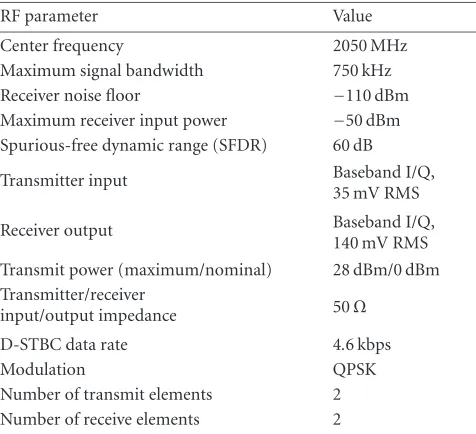
Table1: Key parameters of the VT-STAR.
RF parameter Value
Center frequency 2050 MHz
Maximum signal bandwidth 750 kHz
Receiver noise floor −110 dBm
Maximum receiver input power −50 dBm Spurious-free dynamic range (SFDR) 60 dB
Transmitter input Baseband I/Q,
35 mV RMS
Receiver output Baseband I/Q,
140 mV RMS Transmit power (maximum/nominal) 28 dBm/0 dBm Transmitter/receiver
input/output impedance 50Ω
D-STBC data rate 4.6 kbps
Modulation QPSK
Number of transmit elements 2 Number of receive elements 2
The RTDX feature of the C67 supports host target commu-nications at the receiver side, and offers both real-time moni-toring of physical layer parameters (e.g., bit error rate, diver-sity gain, constellation diagrams) and data acquisition op-eration. A host PC, which runs a multithreaded application to manage a Matlab session, is used to display the physical layer parameters, or perform postprocessing of stored data. Table 1summarizes key parameters used in the design of the VT-STAR.
3. TRANSMITTER
TMS320C67
DSK
THS5661 DAC board
THS5661 DAC board
THS5661 DAC board
THS5661 DAC board Q2
I2
Q1
I1
I/Q Mod ZFMIQ-70ML
Splitter ZESC-2-11
I/Q Mod ZFMIQ-70ML
ZEM-4300
×
68 MHz Signal gen 1982 MHz
1982 MHz
ZEM-4300
×
BPF fo=2050 MHz
10 MHz ref
BPF fo=2050 MHz
Atten.
2050 MHz
2050 MHz Splitter ZESC-2-11
Figure2: Transmitter architecture.
boards were operated in parallel to emulate a 4-channel DAC. The THS5661 DAC board is a relatively simple EVM run-ning at a sampling rate of up to 100 MSPS with 12-bit input data resolution. The time synchronization between the DACs was maintained by driving them from a single clock from the DSK. Finally, the analog output signals were fed to the RF chains where the signals get upconverted to the RF carrier frequency of 2.05 GHz. The phase synchronization between the RF chains was maintained by driving them with the same local oscillator (LO).
3.1. D-STBC algorithm on the transmitter
The STBC algorithm implemented on VT-STAR is the differential-STBC (D-STBC) with simple maximum likeli-hood (ML) detection [20]. D-STBC has the main advantage of rendering carrier phase recovery and channel estimation unnecessary. This feature allows for a far simpler implemen-tation of STBC as the first prototype. The functional blocks that were implemented include QPSK and M mappings, dif-ferential encoding, and STBC.
3.2. Software implementation of D-STBC on the C67
Prior to implementing the algorithms on the DSP, a com-plete link level simulation was developed in Matlab. The sim-ulation tools played an important role in the design process of the radio, providing a verification of system-level issues such as performance versus complexity tradeoffs. These tools also act as a source for generating test vectors for validat-ing the different DSP functional blocks, simplifying the de-bugging process of the DSP code. The flow diagram of the software implementation on the C67 is shown inFigure 3. A pseudonoise (PN) generator was used to generatem-length PN sequence that acted as the input information stream. The information bits are modulated by QPSK mapping and encoded by core D-STBC processing. The resulting base-band complex symbols, I1, Q1 for antenna 1 and I2, Q2for antenna 2, were individually pulse shaped by square-root-raised-cosine (SRRC) filters with rollofffactor of 0.35. The pulse-shaping filters are of finite impulse response (FIR) fil-ters with 19 taps. Four filfil-ters (I and Q each for two antennas) with oversampling factor of 3 were implemented. Simula-tion results indicated that oversampling of 3 samples/symbol would suffice and result in less than 0.5 dB degradation as
To 4xTI THS1556 EVMs Data Packing Pulse shaping
I1
Pulse shaping Q1
Pulse shaping I2
Pulse shaping Q2
Space-time block coding Differential
encoding M mapping
QPSK mapping
Source (PN generator)
Delay
Figure3: Transmitter software flowchart.
compared to the performance of the system with 4 sam-ples/symbol. The design choice of 3 samples/symbol allowed us to reduce processing load and increase throughput with minimum penalty in performance. Finally, the filter out-puts were properly formatted in the data-packing segment to match the output interface requirements. This segment is described in details as follows.
PN generator
1193
QPSK map 1008
M map 1228
Core STBC 1293
Pulse shape 57852
0 1 2 3 4 5 6 7
Clo
ck
cy
cles
×104
Figure4: Profiling results of the transmitter code structure (number of DSP clock cycles).
interface design. The DACs were addressed through mem-ory mapped addressing in the CE1 space of the DSP. The related timing parameters, for example, hold time and rise time, were checked to ensure that they matched the timing specifications of the data converters. The write operations generate a periodic control signal that is used as an external clock to the DACs.
Certain level of code optimization was performed by writing the computationally dominant pulse-shaping filter-ing in assembly language. Profilfilter-ing was performed on the overall code for an instruction cycle of 6.7 nanoseconds, and the resulting number of clock cycles required for each func-tional block is shown inFigure 4. The cycle counts inFigure 4 represent time required for 4 information bits. Pulse-shaping block represents SRRC filtering in assembly on 24 samples and presents itself as the most computationally intensive pro-cess. PN generator and data packing dominate the remaining processes.
3.3. Transmitter I/O mechanisms
Real-time generation and transmission of data at a constant rate was maintained through the use of both the software-and hardware-driven interrupt capabilities of the DSP BIOS configuration section of the DSK. The output scheme was based on a double output buffer concept. When one buffer was used for storing STBC encoded symbols, the other buffer was used for transmitting previously stored symbols to the output port, and vice versa. A high-priority hardware in-terrupt (HWI), driven by timer 0 (T0) with time period
T = 144 milliseconds, services an interrupt service routine (ISR) that accesses one buffer and transmits a 32-bit TX word to the interface board. During HWI intervals, a low-priority software interrupt (SWI) performs D-STBC encoding pro-cess and stores a 32-bit TX word to the other buffer. The timer period T is chosen such that the SWI rate is slightly faster than the HWI rate, and the SWI process waits after fill-ing up its designated buffer until the HWI process is done transmitting all the contents of its buffer. The DSP BIOS ca-pabilities have been used to monitor and maintain all the
process control works so as to achieve a real-time implemen-tation and transmission at a certain constant rate.
Routing of digital data from the DSP to the four DACs (one for I and Q for each antenna element) required spe-cial data distribution and custom hardware to support the distribution mechanism. Two boards were designed and fab-ricated to interface the nonstandard 50-mil 80-pin connec-tor J1 on the DSK to the standard 100-mil connecconnec-tor on the DACs. Data routing or signal distribution included splitting the clock signal via a clock distribution chip (CDC) and split-ting the 32-bit TX word into four 8-bit words and connecsplit-ting them to the 8 MSB (each DAC is 12-bit) [21]. The write en-able (XWE) signal, acting as the master clock, was distributed by the CDC and the outputs were synchronized within 50 nanoseconds. This is considered to be a satisfactory keeping in mind the long sampling interval of 144 milliseconds. An additional RC network was introduced to each DAC to re-move the DC bias from its single-ended outputs, to avoid transmission of the carrier signal.
3.4. Transmitter RF front end
The RF section is based on two-stage upconversion with a 68 MHz IF for each antenna element and the two RF chains were phase-synchronized with common local oscil-lators (LO). The upconverted signal centered on 2050 MHz RF carrier was transmitted by two vertically polarized, copla-nar, quarter-wavelength monopole antennas. Monopole an-tennas were selected because of their simple design, demon-strating that performance gains can be realized using anten-nas that are practical for handheld wireless devices. Antenna spacing can be varied on the VT-STAR to test the perfor-mance of the system versus antenna spacing for different ra-dio environments.
4. RECEIVER
2050 MHz BPF 2050 MHz
ZHL-1724 HLN
ZEM-4300
ZFL-1000 GH
68 MHz
BPF 68 MHz
ZFL-1000 H
I/Q demod ZFMIQ-70D
× ×
1982 MHz 1982 MHz
AGC AGC Splitter
ZESC-2-11 2050 MHz
BPF 2050 MHz
ZHL-1724 HLN
ZEM-4300
ZFL-1000 GH
BPF 68 MHz
10 MHz ref
ZFL-1000 H
I/Q demod ZFMIQ-70D
Splitter ZESC-2-11
I1
Q1
I2
Q2
SLP1.9 LPF
LPF
LPF
LPF SLP1.9
THS1206
AD
C
TMS320C67
DSP
Figure5: Receiver architecture.
The receiver front end uses two vertically polarized, coplanar, quarter-wavelength monopole antennas to receive the signals, centered at 2050 MHz. The signals are amplified, downconverted to baseband via IF and sampled by the mul-tichannel THS1206 ADC EVM. The C67 DSP software per-forms space-time decoding in real-time mode or collects raw data as a data acquisition unit in snapshot mode. The host PC is used for control of the DSP via TI’s code composer, for display and storage of relevant physical layer parameters, and, when applicable, for the postprocessing of raw data in Matlab.
4.1. Receiver RF front end
The receiver RF front end is based on two-stage downconver-sion with an IF of 68 MHz. The receiver RF chains were de-signed to accept automatic gain control (AGC) signals so that the DSP can control the gain of the RF front end. Imbalances between the I and Q channels of the chains are characterized and compensated with scaling factors at the DSP.
4.2. Receiver I/O
The multichannel THS 206 ADC EVM selected for the in-terface between the RF front end and the DSP has a maxi-mum sampling rate of 1.5 MSPS/channel with a resolution of 12 bits [22,23]. This maximum sampling rate was not uti-lized, since the computational complexity of the decoding al-gorithms at the receiver DSP on the receiver side would over-whelm the processor. The ADC uses an internal FIFO of vari-able length (up to 16 words) to store digitized received sam-ples and generates a hardware interrupt when the FIFO gets filled to a preset depth. The DSP executes an ISR to retrieve the samples from the FIFO. The real-time sample retrieval re-lies on alternating double-buffer concept with an appropriate sampling rate similar to the one used on the transmitter side.
4.3. Receiver operating modes
The VT-STAR receiver has two modes of operation: contin-uous mode and data acquisition mode. In the contincontin-uous mode, the receiver DSP operates in real-time, performing full space-time demodulation and decoding and sending rel-evant physical layer parameters to the host PC via the RTDX.
This mode is used to demonstrate the capabilities of time coding and to study the interactions between space-time decoding, timing and phase recovery, and channel es-timation. In the data acquisition mode, it collects raw data into buffers and dumps the buffer contents into the host PC hard drive for postprocessing in Matlab. This mode is used to characterize indoor MIMO channel in terms of spatial and temporal characteristics, achievable throughput and link re-liability. These two modes are discussed in the following sub-sections.
4.3.1. Real-time mode
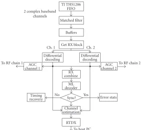
This mode of operation is supported by several functional blocks: matched filtering, differential decoding, bit and block synchronization, RX combining, channel estimation, and RTDX. The raw in-phase and quadrature samples, collected from the ADC FIFO, are first processed by a squared-root-raised-cosine (SRRC) matched filter with rollofffactor 0.35 (the same filter specs at the transmitter side). These filters were implemented in hand-coded assembly for speed opti-mization. These filtered samples are then differentially de-modulated which undergo bit and block synchronization. AGC is performed with a first-order IIR filter on the diff eren-tially demodulated symbols to estimate average gain on each channel (antenna element). Note that the AGC is performed per channel in order to compensate for chain mismatch and obtain a nominal signal level at the ADC output. Since the AGC amplifies (or attenuates) the sum of signal and noise, it does not change the SNR and thus the combining procedure is not affected by the mechanism.
Block synchronization module finds the “borders” of the ST block such that the differential demodulation pro-cess can be performed correctly. The bit synchronizer de-termines which sample (out of 3 samples per symbol) is the best instant and decimates the signal accordingly. Both syn-chronization modules are based on correlation processing of known (training) sequences that are transmitted periodi-cally. ML detection is performed by finding the constellation point that is the closest (in terms of Euclidean distance) to the decision statistics after decoding and combining.
TI THS1206 FIFO 2 complex baseband
channels
Matched filter
Buffers
Get RX block
Ch. 1 Ch. 2
Differential
decoding Didecodingfferential To RF chain 1 AGC
channel 1 channel 2AGC
To RF chain 2 RX
combine ML decoder Timing
recovery
No
Sync? Yes Error stats
Channel estimation
RTDX To host PC
Figure6: Receiver software flowchart.
differential reencoding over the decoded bits. Let us denote
the MIMO channel estimates by ˆα =
ˆ
α1 1 αˆ21 ˆ
α1 2 αˆ22
. These
esti-mates are achieved through the following linear processing:
˜
α1j= r j
t ·sˆ1
∗−rj
t+T·sˆ2
sˆ12+sˆ22
, j=1, 2,
˜
α2j= rtj·s2
∗
+rt+Tj ·s1 s12
+s2
2 , j=1, 2,
(1)
wherertj rtj+Tforj=1,2 denotes the 4 consecutive samples at the matched filter output.
It is important to note that the channel estimation pro-cess takes place in order to allow for monitoring of the MIMO channel. The channel estimation algorithm is based on a “decision-directed” mode, and is operated only when the error rate is below an acceptable level to avoid the error propagation problem.
Figure 6shows a flow diagram of the receiver software implemented on the C67 DSP, where the different opera-tions described above are mapped into software. The soft-ware shown inFigure 5was profiled, yielding the cycle counts shown inFigure 7. Profiling on the receiver DSP operated on instruction cycles with duration of 7.5 nanoseconds. The cy-cle count for matched filtering operation is different from the pulse-shaping operations in Figure 4 because the matched filtering at the receiver includes additional tasks such as re-arranging the filter output and decimation. Following the filtering operation, the next most computationally intensive
Get RX block
512
Differential decoding
399
AGC 175
Receive combine
137
ML
detectionFiltering 1248
20364
0 5 10 15 20 25×10
3
Figure7: VT-STAR receiver DSP profiling results.
operation is the maximum likelihood (ML) detection, while the remaining STBC operations consume a small number of clock cycles.
4.3.2. Communications between DSP receiver and host PC
2 1.5 1 0.5 0
−0.5
−1
−1.5
−2
−2 −1 0 1 2
(a)
5
0
−5
−5 0 5
(b)
−70
−75
−80
−85
−90
−95
−100
20 40 60 80 100
(c) 2
1.5
1
0.5
0
0 0.1 0.2 0.3 0.4 (d)
1
0.8
0.6
0.4
0.2
0
−40 −30 −20 −10 0 10
(e)
1 0.5 0
−8 −7 −6 −5 −4 −3
BER SISO 1
0.5 0
−8 −7 −6 −5 −4 −3
BER MIMO (f)
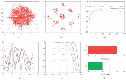
Figure8: Host computer display. ((a) MF output, (b) STP output, (c) automatic gain control, (d) MIMO channel estimation, (e) diversity advantage, and (f) bit error rate.)
asynchronously since the host may require a lengthy amount of time to display the received information and process the reply.
4.3.3. Matlab display
The data collected by the host PC is passed to the Matlab en-vironment for postprocessing and display. A sample of the telemetry data sent from the receiver processor is shown in Figure 8, including constellation diagrams at the matched fil-ter output before and affil-ter the decimation process (oversam-pling factor=3), AGC curves for estimated received signal power in dBm, fading profiles of the MIMO channel, diver-sity gain curves, and bit error rate (BER) measurements. This sample was collected from the target DSP by using synthetic data at the input to the DSP. It validates the real-time pro-cessing at the DSP and the communication protocol with the host PC via RTDX.
4.3.4. Data acquisition mode
In order to collect and store snapshots of data, the C67 uses its RTDX utility to perform transfer of data from the target (DSP) to the host (PC) without affecting other real-time op-erations on the DSP as shown inFigure 9.
The RTDX utility provides application protocol interface (API) commands to set up an RTDX channel between the DSP and the PC. Data collected in a buffer in the DSP is
first passed to the target RTDX library in the form of mes-sages consisting of a group of words. The target library then sends one message at a time to the host RTDX library by is-suing low-priority message interrupt (MSGINT) during the idle cycles of the DSP. This ensures that no data is lost or overwritten during the transfer process. This transfer takes place over the JTAG interface. The debugger controls the host RTDX library such that the received messages at the host are stored in a log file.
The data acquisition buffer depth is set to collect snap-shots of 1200 samples. Four words corresponding to in-phase and quadrature samples for antennas 1 and 2 are stored in the buffer at each hardware interrupt from the ADC. After filling up this buffer, this data is transferred to the RTDX target li-brary in the form of messages consisting of 10 words. Before initiating this RTDX transfer, the ADC interrupt is disabled hence making the DSP idle for the transfer to take place. The transfer is initiated by a software interrupt, generated every 1 millisecond period, which sets up the RTDX channel trans-fer. This period is sufficient to ensure complete transfer of 10 data samples or one message from the target to the host library using RTDX. The ADC hardware interrupt is reen-abled after completion of data transfer of all the 1200 data samples in the buffer.
Host
.bin log file for Matlab post
processing
TI debugger
C++ program for .rtd to .bin log file
conversion
COM interface
Host RTDX library
Log file
JTAG interface Target RTDX library
RTDX channel
Target application Target
Msg (10 samples)
Buffer 1
1200
Figure9: RTDX in snapshot mode.
debugger is used to halt the DSP. The .rtd log file is played back by the code composer utility and a C++ program, which uses the component object model (COM) interface provided by the code composer to convert this file into a binary format. This binary file contains all sample values received from the ADC, and is used for postprocessing by the Matlab software.
4.3.5. Postprocessing
The postprocessor operates on the raw samples by passing them via matched filter, removing residual frequency offsets and performing correlation processing to extract the chan-nel fade coefficients. Once the channel matrix is obtained, it is embedded into the calculation of the channel capacity for various antenna configurations (i.e., single antenna system, transmit diversity, receive diversity, and MIMO channel).
5. MIMO CAPACITY MEASUREMENTS RESULTS
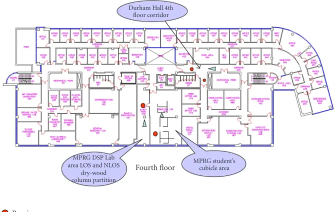
Some representative measurements for MIMO channel char-acterization performed in various indoor locations and the resulting capacity are presented in this section. Capacity in this case refers to throughput, normalized with respect to the bandwidth and is measured as bps/Hz. The measurements were carried out in three locations: 478 MPRG DSP Lab, 476 MPRG student cubicle area, and the Durham Hall 4th floor corridor as shown in floor plan in Figure 10. The receiver was stationary while the transmitter was placed in different locations. The total numbers of measurements were twenty, eleven, and eight for the DSP Lab, cubicle area, and the corri-dor, respectively, where each measurement provided twenty MIMO channel estimates. DSP Lab and the student cubicle area provided non-line-of-sight (NLOS) propagation chan-nel while the corridor measurements included both line-of-sight (LOS) and NLOS channels. For each measurement campaign, movement was minimized to ensure a quasistatic channel. Throughout the measurement campaign, calibra-tion process took place to guarantee small frequency offset (at the order of 20 Hz). This residual frequency error was
calculated and compensated in the postprocessing module prior to the channel estimation process, by phase adjustment of the symbols according to their position in the buffer.
To calculate the capacity of the MIMO channel, we use the key result of Foschini and Gans in [1]:
C=log2det
InR+ SNR
nT
H·H†, (2)
where H = {hij}andH† is the transpose conjugate ofH. Each elementhijrefers to the channel gain fromith transmit antenna to thejth receive antenna. SNR is the signal-to-noise ratio at the jth receive branch andInR is annR×nRidentity matrix.Figure 11apresents measured capacity at a particular location in NLOS environment (DSP Lab) for a fixed 20 dB SNR for MIMO system as well as each one of the SISO links (Ch11,Ch12,Ch21, andCh22). With the use of 2×2 antenna array configuration, twofold capacity increase is observed as compared to any one of the SISO channels. Such a twofold increase in normalized throughput will result in significant increase in data rate for a wideband system.
Next, we compare the capacity of the MIMO chan-nel with the capacity achieved by a single-input multiple-output (SIMO) channel with either optimal combining (OC) or diversity selection (DS) criteria, multiple-input single-output (MISO) channel employing transmit diversity only and single-input single-output (SISO) channel. Figure 11b illustrates the measured complementary cumulative distri-bution functions (CCDFs) for these cases. Similar to the the-oretical results of [1], MIMO channel capacity outperforms receive (SIMO) or transmit diversity (MISO). The measured CCDF plot for MIMO has generally the same trend as shown in [11]. Note that, receive diversity outperforms transmit di-versity due to the power splitting in MISO, and, within re-ceive diversity schemes, optimal combining outperforms se-lection diversity.
MPRG DSP Lab area LOS and NLOS
dry-wood column partition
Durham Hall 4th floor corridor
MPRG student’s cubicle area Fourth floor
Receiver Transmitter
Figure10: Floor plan of the fourth floor of Durham Hall.
h
14
12
10
8
6
4
2
Capacit
y
(bps/Hz)
0 10 20 30 40 50 60 70 80
Time (s) Ch11
Ch12
Ch21
Ch22
CMIMO
(a)
1 0.9 0.8 0.7 0.6 0.5 0.4 0.3 0.2 0.1 0
Pro
b
(c
ap
ac
it
y
>
Th)
2 4 6 8 10 12 14
Capacity (bps/Hz) SISO channel:nT=1;nR=1 MISO channel:nT=2;nR=1 SIMO channel (SD):nT=1;nR=2 SIMO channel(OC):nT=1;nR=2 MIMO channel:nT=2;nR=2
(b)
Figure11: (a) Channel capacity; SISO versus MIMO channel. (b) CCDF plots of capacity for SISO, SIMO, MISO, and MIMO for 20 dB SNR.
cumulative distribution functions (CCDFs) are presented in Figure 12. We observe that only 30% of channel realizations will achieve capacities comparable to those measured in our lab. The difference between the measured range of capaci-ties in indoor environments and the theoretical performance
1 0.9 0.8 0.7 0.6 0.5 0.4 0.3 0.2 0.1 0
Pro
b
(c
ap
ac
it
y
>
Th)
0 2 4 6 8 10 12 14 16 18 20
Capacity (bps/Hz) SISO channel:nT=1;nR=1 MISO channel:nT=2;nR=1 SIMO channel (SD):nT=1;nR=2 SIMO channel(OC):nT=1;nR=2 MIMO channel:nT=2;nR=2
Figure12: Theoretical capacity; SNR=20 dB.
perform measurements to assess the achievable capacity im-provements in real-life propagation channels.
The MIMO capacity evaluations from channel measure-ments for the three different indoor environments are sum-marized in Table 2.Table 2 presents estimated average ca-pacity for the single channel, optimum combining (the best among the transmit/receive diversity schemes), and MIMO. The values indicate the superior performance from MIMO systems in all environments even in LOS case. Note that al-though the LOS propagation causes the individual antenna elements to be more correlated than NLOS case, however, the presence of indoor scattering environment can provide suf-ficient decorrelation that enables MIMO system to perform better than SISO or SIMO in an NLOS scenario.
6. CONCLUSION
This paper presented the design and development of a MIMO system prototype capable of performing multiple tasks through the modification of software. We presented an overview of the VT-STAR platform which implements both D-STBC and MIMO channel measurements. The transmit-ter and receiver sections of VT-STAR were examined in de-tail, outlining some of the challenges and design issues that needed to be resolved in the development of this prototype. The implementation of the D-STBC algorithm has verified that the algorithm is robust to arbitrary phase errors and to frequency mismatch of 1 KHz of the local oscillators at the receiver. The D-STBC algorithm, which was designed originally for quasistatic environments, works well in slow time-varying environments (e.g., indoor wireless commu-nications). Capacity improvements were observed through the use of MIMO technology. VT-STAR has an open SDR
Table2: Comparison of measured capacity for SISO, SIMO, and MIMO systems.
Environment Capacity (bps/Hz)
SISO SIMO (opt. comb.) MIMO
DSP Lab 6.2 7.8 9
Cubicle area 7 7.5 10.2
Corridor (LOS) 6.7 7.9 9.2
Corridor (NLOS) 6.8 8.4 10.2
architecture, allowing the expansion of its capabilities as the needs arise, showing the flexibility of the design and the ef-ficacy of system implementation of systems on DSP. Fur-thermore, this design has indicated that MIMO technology is viable for rapid prototyping and implementation with COTS components in the future. Future studies with revised hardware versions will include increased bandwidth system, channel characterization with variable antenna spacing and different antenna geometry, and a comparison of measured and theoretical BER versus SNR curves for the D-STBC algo-rithm.
ACKNOWLEDGMENTS
This work was supported by the MPRG Industrial Affiliates and the Navy Collaborative Integrated Information Tech-nology Initiative (NAVCIITI) under Grant N00014-00-1-0549; this paper was presented in part in “Software radios: a modern approach to radio engineering,” by Jeffrey H. Reed, Prentice-Hall, in the 2001 IEEE Radio and Wireless Con-ference (RAWCON ’01), Boston, Mass, and in the 2002 Ve-hicular Technology Conference (VTC Fall ’02), Vancouver, Canada.
REFERENCES
[1] G. J. Foschini and M. J. Gans, “On limits of wireless commu-nications in a fading environment when using multiple an-tennas,”Wireless Personal Communications, vol. 6, no. 3, pp. 311–335, 1998.
[2] V. Tarokh, N. Seshadri, and A. R. Calderbank, “Space-time codes for high data rate wireless communication: perfor-mance criterion and code construction,”IEEE Trans. Inform. Theory, vol. 44, no. 2, pp. 744–765, 1998.
[3] S. M. Alamouti, “A simple transmit diversity technique for wireless communications,” IEEE J. Select. Areas Commun., vol. 16, no. 8, pp. 1451–1458, 1998.
[4] TIA, TR45.5, Physical Layer Standard for CDMA2000 Spread Spectrum Systems. TIA/EIA/IS-2000.2, 1999.
[5] R. Gozali and B. D. Woerner, “The impact of channel esti-mation errors on space-time trellis codes paired with iterative equalization/decoding,” inProc. IEEE 55th Vehicular Technol-ogy Conference (VTC ’02), vol. 2, pp. 826–831, Birmingham, Ala, USA, May 2002.
[6] R. Gozali, R. Mostafa, R. C. Palat, et al., “Virginia tech space-time advanced radio (VT-STAR),” inProc. IEEE Radio and Wireless Conference (RAWCON ’01), pp. 227–231, Waltham, Mass, USA, August 2001.
Electromagnetic Range Consortium Meeting, The Ohio State University ElectroScience Laboratory, Columbus, Ohio, USA, July 2001.
[8] M. Stoytchev, J. B. Raveche, and H. F. Safar, “Joint spatial and temporal characterization of the wideband wireless com-munication channel for MIMO applications,” inProc. IEEE Radio and Wireless Conference (RAWCON ’01), pp. 233–236, Waltham, Mass, USA, August 2001.
[9] J. P. Kermoal, L. Schumacher, P. E. Mogensen, and K. I. Peder-sen, “Experimental investigation of correlation properties of MIMO radio channels for indoor picocell scenarios,” inProc. 52nd IEEE VTS-Fall Vehicular Technology Conference (VTC ’00), vol. 1, pp. 14–21, Boston, Mass, USA, September 2000. [10] J. W. Wallace and M. A. Jensen, “Experimental
characteriza-tion of the MIMO wireless channel,” inProc. IEEE Antennas and Propagation Society International Symposium, vol. 3, pp. 92–95, Boston, Mass, USA, July 2001.
[11] K. Yu, M. Bengtsson, B. Ottersten, D. McNamara, P. Karls-son, and M. Beach, “Second order statistics of NLOS indoor MIMO channels based on 5.2 GHz measurements,” inProc. IEEE Global Telecommunications Conference (GLOBECOM ’01), vol. 1, pp. 156–160, San Antonio, Tex, USA, November 2001.
[12] C. C. Martin, J. H. Winters, and N. R. Sollenberger, “Multiple-input multiple-output (MIMO) radio channel measure-ments,” inProc. IEEE Antennas and Propagation Society Inter-national Symposium, vol. 1, pp. 418–421, Boston, Mass, USA, July 2001.
[13] M. J. Gans, N. Amitay, Y. S. Yeh, et al., “Outdoor BLAST mea-surement system at 2.44 GHz: calibration and initial results,” IEEE J. Select. Areas Commun., vol. 20, no. 3, pp. 570–583, 2002.
[14] M. Guillaud, A. Burg, M. Rupp, E. Beck, and S. Das, “Rapid prototyping design of a 4×4 BLAST-over-UMTS system,” in Proc. Conference Record of the 35th Asilomar Conference on Signals, Systems and Computers, vol. 2, pp. 1256–1260, Pacific Grove, Calif, USA, November 2001.
[15] A. F. Molisch, M. Steinbauer, M. Toeltsch, E. Bonek, and R. S. Thoma, “Capacity of MIMO systems based on measured wireless channels,” IEEE J. Select. Areas Commun., vol. 20, no. 3, pp. 561–569, 2002.
[16] A. van Zelst and T. C. W. Schenk, “Implementation of a MIMO OFDM-based wireless LAN system,”IEEE Trans. Sig-nal Processing, vol. 52, no. 2, pp. 483–494, 2004.
[17] P. Murphy, F. Lou, A. Sabharwal, and J. P. Frantz, “An FPGA based rapid prototyping platform for MIMO systems,” in Proc. Conference Record of the 37th Asilomar Conference on Signals, Systems and Computers, vol. 1, pp. 900–904, Pacific Grove, Calif, USA, November 2003.
[18] R. M. Rao, W. Zhu, S. Lang, et al., “Multi-antenna testbeds for research and education in wireless communications,”IEEE Commun. Mag., vol. 42, no. 12, pp. 72–81, 2004.
[19] TMS320C62x/C67x Programmer’s Guide, SPRU198B, Texas Instruments, 1998.
[20] V. Tarokh and H. Jafarkhani, “A differential detection scheme for transmit diversity,”IEEE J. Select. Areas Commun., vol. 18, no. 7, pp. 1169–1174, 2000.
[21] THS56x1EVM for the THS5641/51/61/71 8-Bit, 10-Bit, 12-Bit, 14-Bit D/A Conversion, SLAU032A, Texas Instruments, 1999.
[22] THS1206, THS12082, THS10064, THS10082 Evaluation Module User’s Guide, SLAU042A, Texas Instruments, 1999. [23] Designing With the THS1206 High-Speed Data Converter
Application Report, SLAA094, 1999.
[24] TMS320C6000 Real-Time Data Exchange (RTDX) Tutorial, Texas Instruments, 1998.
[25] R. Gozali, R. Mostafa, R. C. Palat, et al., “MIMO chan-nel capacity measurements using the VT-STAR architecture,” in Proc. 56th IEEE Vehicular Technology Conference (VTC ’02), vol. 2, pp. 884–888, Vancouver, BC, Canada, September 2002.
Raqibul Mostafa received his B.S. degree in electrical and electronics engineering in 1991 from Bangladesh University of En-gineering and Technology. He worked as a Lecturer in the Department of Electri-cal and Electronics Engineering of the same university for a year and a half before com-ing to Virginia Tech for graduate study. He obtained his M.S. and Ph.D. degrees in elec-trical engineering from Virginia Tech.
Dur-ing his graduate studies at MPRG, he conducted research on an-tenna array algorithms and applications for handheld terminals, propagation measurement for smart antenna, and feasibility of smart antenna for 3G and WLAN standards. He worked as a post-doctoral research faculty member in the MPRG Lab at Virginia Tech for a year. He is now currently employed with Qualcomm Inc.
Ran Gozali received his Ph.D. degree in electrical and computer engineering from Virginia Tech in 2002 and his B.S. degree (magna cum laude) in electrical and com-puter engineering from Ben Gurion Uni-versity, Israel, in 1994. From 1994 to 1999, he was a member of the technical staffat Rafael, Israel, conducting research that sup-ports algorithm development of advanced wireless modems. Currently, Gozali is
lead-ing the Communications and Algorithms Group at Rafael, design-ing physical layer algorithms for wireless military networks. His research interests include space-time coding and MIMO systems, OFDM, turbo codes, and radio system technology.
Ramesh Chembil Palatis a Ph.D. student in electrical engineering at Virginia Tech. He received his B.Tech. and M.S. degrees in electrical engineering from the Univer-sity of Calicut, India, and Virginia Tech, in 1998 and 2002, respectively. He worked as a Software Engineer with Infosys Technolo-gies Ltd. in 1999. During the summers of 2001 and 2002, he worked with Analog De-vices Inc. and Microsoft Research,
respec-tively. His research interests include space-time signal processing and software radios.
William G. Newhallreceived his B.S., M.S., and Ph.D. degrees from Virginia Tech in Blacksburg, Virginia. He performed his graduate work at the Mobile and Portable Radio Research Group, Virginia Tech, where he performed research in the areas of software-defined radio, RF design, wide-band propagation measurements, and ra-dio channel modeling for antenna arrays. He was the recipient of the Virginia Space
Grant Consortium Aerospace Fellowship, the Davenport Fellow-ship, the General Motors ScholarFellow-ship, and the Radio Club of Amer-ica Scholarship. In 1996, he joined Grayson Wireless (now Andrew Corporation) where he developed test and measurement equip-ment for wireless telephone networks. In 2003, Dr. Newhall joined Ball Aerospace & Technologies Corp. in Boulder, Colorado, where he develops RF systems for integrating legacy and joint tactical ra-dio system (JTRS) rara-dios into military platforms. His current re-search involves communication system simulation, radio system performance analysis, and cosite interference mitigation.
Brian D. Woernerreceived his B.S. degree in computer and electri-cal engineering from Purdue University in West Lafayette, Ind, in 1986. He received his M.S. and Ph.D. degrees in electrical engineer-ing systems from the University of Michigan at Ann Arbor in 1987 and 1991, respectively. During his Ph.D. studies he was a recipient of the University of Michigan’s Benton Fellowship and Unisys Fel-lowship. He also holds a Master’s of Public Policy degree from the University of Michigan’s Institute of Public Policy Studies, with an emphasis on telecommunications policy.